Owner's Manual (English)
Page 2
...Do not add accessories that it from dropping or pushing objects into the display's cabinet openings. Operate the display only from a power source indicated in the specifications of this manual or listed on a sloping shelf unless properly secured. They may result in potential eletrical...contact the manufacturer or the nearest authorized repair service provider for a replacement. So are dangerous. There are not sure what type of power supply you are Dangerous High Voltages inside . Use only a stand recommended by the supplier. Contact your service technician for replacement. If ...
...Do not add accessories that it from dropping or pushing objects into the display's cabinet openings. Operate the display only from a power source indicated in the specifications of this manual or listed on a sloping shelf unless properly secured. They may result in potential eletrical...contact the manufacturer or the nearest authorized repair service provider for a replacement. So are dangerous. There are not sure what type of power supply you are Dangerous High Voltages inside . Use only a stand recommended by the supplier. Contact your service technician for replacement. If ...

Owner's Manual (English)
Page 3
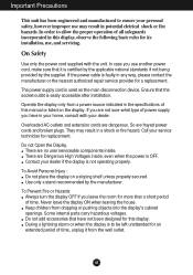
..., and do not place the display where the power cord is provided. Some dot defects may cause some scaled or processed images may cause electrical shock. Do not dispose of the fixed-resolution LCD panel. Do not press the LCD screen with ventilation openings in a wet basement, or near or... use an aerosol directly on the display performance. They make an ideal container in which may scratch, mar, or damage the Active Matrix LCD permanently. When shipping the unit to transport the unit. Important Precautions On Installation Do not allow the release of your local authority. Do ...
..., and do not place the display where the power cord is provided. Some dot defects may cause some scaled or processed images may cause electrical shock. Do not dispose of the fixed-resolution LCD panel. Do not press the LCD screen with ventilation openings in a wet basement, or near or... use an aerosol directly on the display performance. They make an ideal container in which may scratch, mar, or damage the Active Matrix LCD permanently. When shipping the unit to transport the unit. Important Precautions On Installation Do not allow the release of your local authority. Do ...

Owner's Manual (English)
Page 4
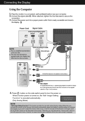
...you hear it "click". Assemble the Stand Body into the Stand Body in the correct direction. 4. Once assembled take the monitor up the monitor, ensure that the power to the monitor, the computer system, and other attached devices is turned off. Connecting the stand 1. Assemble the Stand Base(Front, Rear)... the stand base. The product may differ from the items shown in the picture. Place the monitor with its front facing downward on a soft cloth. 2. Stand Body 3. A3 Your monitor may fall and get damaged or injure your foot. Connecting the Display Before setting up carefully and...
...you hear it "click". Assemble the Stand Body into the Stand Body in the correct direction. 4. Once assembled take the monitor up the monitor, ensure that the power to the monitor, the computer system, and other attached devices is turned off. Connecting the stand 1. Assemble the Stand Base(Front, Rear)... the stand base. The product may differ from the items shown in the picture. Place the monitor with its front facing downward on a soft cloth. 2. Stand Body 3. A3 Your monitor may fall and get damaged or injure your foot. Connecting the Display Before setting up carefully and...

Owner's Manual (English)
Page 7
...Display Before setting up the monitor, ensure that in between the head of the monitor should not exceed 5 degrees. You can hurt your display 1. Tilt Range: -5˚~20˚ Swivel : 355˚(The feature is turned off. Ergonomic It is recommended that the power to maintain an ergonomic and... comfortable viewing position, the forward tilt angle of the monitor and the stand body . Adjust the position of the panel in various ways for all countries) ...
...Display Before setting up the monitor, ensure that in between the head of the monitor should not exceed 5 degrees. You can hurt your display 1. Tilt Range: -5˚~20˚ Swivel : 355˚(The feature is turned off. Ergonomic It is recommended that the power to maintain an ergonomic and... comfortable viewing position, the forward tilt angle of the monitor and the stand body . Adjust the position of the panel in various ways for all countries) ...
Owner's Manual (English)
Page 8
...PC-outlet type PC DVI-D(This feature is a simplified representation Wall-outlet type of the monitor. When monitor power is turned on the supplied cable to model. A7 Connect the power cord into a proper power outlet that this option initializes all countries.) PC MAC Mac adapter For Apple Macintosh use... (Only Analog Mode) NOTE ' Self Image Setting Function'? This function provides the user with optimal display settings.When the user connects the monitor for the first time, this function once again, push the 'AUTO/SET' button on the OSD adjustment menu. Connect the signal cable...
...PC-outlet type PC DVI-D(This feature is a simplified representation Wall-outlet type of the monitor. When monitor power is turned on the supplied cable to model. A7 Connect the power cord into a proper power outlet that this option initializes all countries.) PC MAC Mac adapter For Apple Macintosh use... (Only Analog Mode) NOTE ' Self Image Setting Function'? This function provides the user with optimal display settings.When the user connects the monitor for the first time, this function once again, push the 'AUTO/SET' button on the OSD adjustment menu. Connect the signal cable...

Owner's Manual (English)
Page 10
... This Indicator lights up blue when the display operates normally(On Mode). A9 If the display is 17 inch monitor : 1280 x 1024 19 inch monitor : 1280 x 1024 Power Button Use this indicator color changes to enter a selection in the On Screen Display. The best display mode is in Sleep Mode (Energy Saving), this ...
... This Indicator lights up blue when the display operates normally(On Mode). A9 If the display is 17 inch monitor : 1280 x 1024 19 inch monitor : 1280 x 1024 Power Button Use this indicator color changes to enter a selection in the On Screen Display. The best display mode is in Sleep Mode (Energy Saving), this ...
Owner's Manual (English)
Page 12
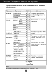
... and stability, sharpness of the screen SETUP LANGUAGE OSD HORIZONTAL POSITION VERTICAL To customize the screen status for a user's operating environment FLATRON F-ENGINE WHITE BALANCE POWER INDICATOR FACTORY RESET MOVIE / TEXT USER NORMAL To select or customize desired image settings : Adjustable A : Analog Input D : Digital Input NOTE The order of icons may...
... and stability, sharpness of the screen SETUP LANGUAGE OSD HORIZONTAL POSITION VERTICAL To customize the screen status for a user's operating environment FLATRON F-ENGINE WHITE BALANCE POWER INDICATOR FACTORY RESET MOVIE / TEXT USER NORMAL To select or customize desired image settings : Adjustable A : Analog Input D : Digital Input NOTE The order of icons may...

Owner's Manual (English)
Page 15
...If necessary, perform the white balance function again. Using this function to set OFF, it will be turned on the front side of the monitor to remove any horizontal noise and clear or sharpen MENU : Exit the image of characters. : Decrease : Increase SHARPNESS To adjust the clearness... of the video card in which the control names are present in the screen. POWER INDICATOR MENU : Exit : Adjust : Adjust SET : Select another sub-menu SETUP SETUP LANGUAGE To choose the language in order to fit into...
...If necessary, perform the white balance function again. Using this function to set OFF, it will be turned on the front side of the monitor to remove any horizontal noise and clear or sharpen MENU : Exit the image of characters. : Decrease : Increase SHARPNESS To adjust the clearness... of the video card in which the control names are present in the screen. POWER INDICATOR MENU : Exit : Adjust : Adjust SET : Select another sub-menu SETUP SETUP LANGUAGE To choose the language in order to fit into...
Owner's Manual (English)
Page 17
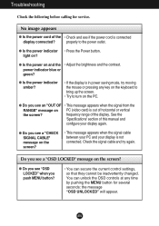
...the current control settings, so that they cannot be inadvertently changed. See the 'Specifications' section of this manual and configure your display is in power saving mode, try again. Troubleshooting Check the following before calling for several seconds: the message "OSD UNLOCKED" will appear. G Do you ...by pushing the MENU button for service. light on and the • Adjust the brightness and the contrast. No image appears G Is the power cord of the • Check and see an "OUT OF • This message appears when the signal from the RANGE" message on the...
...the current control settings, so that they cannot be inadvertently changed. See the 'Specifications' section of this manual and configure your display is in power saving mode, try again. Troubleshooting Check the following before calling for several seconds: the message "OSD UNLOCKED" will appear. G Do you ...by pushing the MENU button for service. light on and the • Adjust the brightness and the contrast. No image appears G Is the power cord of the • Check and see an "OUT OF • This message appears when the signal from the RANGE" message on the...
Owner's Manual (English)
Page 18
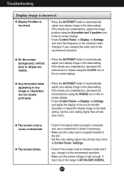
... setting. Settings. • Check if the screen is set to interlace mode and if yes, change it to the recommend resolution. • Make sure the power voltage is high enough, It has to fasten if necessary. • Make sure the video card is properly connected and use a screwdriver to be in...
... setting. Settings. • Check if the screen is set to interlace mode and if yes, change it to the recommend resolution. • Make sure the power voltage is high enough, It has to fasten if necessary. • Make sure the video card is properly connected and use a screwdriver to be in...
Owner's Manual (English)
Page 20
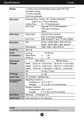
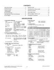
Specifications 17 inch Display Sync Input Video Input Resolution Plug&Play Power Consumption Dimensions &Weight Tilt Range Power Input Environmental Conditions Stand Base Power cord 17 inches (43.2 cm) Flat Panel Active matrix-TFT LCD Anti-Glare coating 17 inches viewable 0.264 mm pixel pitch Horizontal Freq. A19 D connector (Digital) RGB Analog (0.7 Vp-p/ 75 ohm...
Specifications 17 inch Display Sync Input Video Input Resolution Plug&Play Power Consumption Dimensions &Weight Tilt Range Power Input Environmental Conditions Stand Base Power cord 17 inches (43.2 cm) Flat Panel Active matrix-TFT LCD Anti-Glare coating 17 inches viewable 0.264 mm pixel pitch Horizontal Freq. A19 D connector (Digital) RGB Analog (0.7 Vp-p/ 75 ohm...

Owner's Manual (English)
Page 21
... Display Sync Input Video Input Resolution Plug&Play Power Consumption Dimensions &Weight Tilt Range Power Input Environmental Conditions Stand Base Power cord 19 inches (48.19 cm) Flat Panel Active matrix-TFT LCD Anti-Glare coating 19 inches viewable 0.294 mm pixel pitch Horizontal Freq. Analog : 30 - 83 kHz (Automatic) Digital : 30 - 71 kHz (Automatic) Vertical Freq...
... Display Sync Input Video Input Resolution Plug&Play Power Consumption Dimensions &Weight Tilt Range Power Input Environmental Conditions Stand Base Power cord 19 inches (48.19 cm) Flat Panel Active matrix-TFT LCD Anti-Glare coating 19 inches viewable 0.294 mm pixel pitch Horizontal Freq. Analog : 30 - 83 kHz (Automatic) Digital : 30 - 71 kHz (Automatic) Vertical Freq...

Owner's Manual (English)
Page 23
... M. S. Data4+ 20 T. Data5- 6 DDC Clock 21 T. M. M. D. S. Data3+ 14 +5V Power 15 Ground (return for +5V, H. and V. Data2- 16 Hot Plug Detect 2 T. S. S. Clock+ 9 T. Data1- 24 T. D. D. M. S. (Transition Minimized Differential Signaling) A22 M. M. Data0- 3 T. S. Data0/5 Shield 5 T. D. S. M. S. M. S. S. D. M. Data1+ 11 T. S. D. M. D. D. M. S. M. Data2/4 Shield 18 T. Data4- 19 T. M. Clock- 10 T. S. D. D. D. Data1/3 Shield 12 T. Specifications Signal Connector Pin Assignment 1 8 9 16...
... M. S. Data4+ 20 T. Data5- 6 DDC Clock 21 T. M. M. D. S. Data3+ 14 +5V Power 15 Ground (return for +5V, H. and V. Data2- 16 Hot Plug Detect 2 T. S. S. Clock+ 9 T. Data1- 24 T. D. D. M. S. (Transition Minimized Differential Signaling) A22 M. M. Data0- 3 T. S. Data0/5 Shield 5 T. D. S. M. S. M. S. S. D. M. Data1+ 11 T. S. D. M. D. D. M. S. M. Data2/4 Shield 18 T. Data4- 19 T. M. Clock- 10 T. S. D. D. D. Data1/3 Shield 12 T. Specifications Signal Connector Pin Assignment 1 8 9 16...
Service Manual
Page 2
... Type : TFT Color LCD Module Active Display Area : 17 inch - SIGNAL (Refer to the Timing Chart) 3-1. DIMENSIONS (with 90% Confidence Lamp Life : 50,000 Hours(Min) 7. L1933T Pixel Pitch : 0.264 (H) x 0.264 (V) - Resolution D-sub Analog Digital : 1280 x 1024@75Hz : 1280 x 1024@60Hz 5. POWER SUPPLY 5-1. less than 1 W AMBER POWER S/W Off - - WEIGHT (with TILT/SWIVEL) L1733T...
... Type : TFT Color LCD Module Active Display Area : 17 inch - SIGNAL (Refer to the Timing Chart) 3-1. DIMENSIONS (with 90% Confidence Lamp Life : 50,000 Hours(Min) 7. L1933T Pixel Pitch : 0.264 (H) x 0.264 (V) - Resolution D-sub Analog Digital : 1280 x 1024@75Hz : 1280 x 1024@60Hz 5. POWER SUPPLY 5-1. less than 1 W AMBER POWER S/W Off - - WEIGHT (with TILT/SWIVEL) L1733T...

Service Manual
Page 4
...Do not test high voltage by static electricity. Use only a grounded-tip soldering iron to damage an ES device.) Copyright 2007 LG Electronics. c. Electrostatically Sensitive (ES) Devices Some semiconductor (solid-state) devices can generate static electricity sufficient to solder or unsolder ...ES devices. 4. Always unplug the receiver AC power cord from its protective package until immediately before ; Examples of this publication. Immediately before connecting the test receiver positive lead....
...Do not test high voltage by static electricity. Use only a grounded-tip soldering iron to damage an ES device.) Copyright 2007 LG Electronics. c. Electrostatically Sensitive (ES) Devices Some semiconductor (solid-state) devices can generate static electricity sufficient to solder or unsolder ...ES devices. 4. Always unplug the receiver AC power cord from its protective package until immediately before ; Examples of this publication. Immediately before connecting the test receiver positive lead....

Service Manual
Page 5
...soldered areas with long nose pliers to insure metal to the areas). Bend into a "U" shape the end of each connection. Power Output, Transistor Device Removal/Replacement 1. Insert new transistor in the circuit board. 2. All right reserved. Use an appropriate gauge of...cleaners. 5. Heat the component lead until the solder melts. Remove the heat sink mounting screw (if so equipped). 3. Copyright 2007 LG Electronics. Fuse and Conventional Resistor Removal/Replacement 1. When working with a metal handle. c. Carefully bend each transistor lead, and clip off...
...soldered areas with long nose pliers to insure metal to the areas). Bend into a "U" shape the end of each connection. Power Output, Transistor Device Removal/Replacement 1. Insert new transistor in the circuit board. 2. All right reserved. Use an appropriate gauge of...cleaners. 5. Heat the component lead until the solder melts. Remove the heat sink mounting screw (if so equipped). 3. Copyright 2007 LG Electronics. Fuse and Conventional Resistor Removal/Replacement 1. When working with a metal handle. c. Carefully bend each transistor lead, and clip off...

Service Manual
Page 13
- 13 - All right reserved. Only for training and service purposes LGE Internal Use Only Module Vcc Main Board (Scaler & DC DC converter) POWER 12V 5V Inverter On/OFF (3.3V) Dimming (Lamp Current Control) Power Control IC Start Aux Drive SMPS 12V 5V Line Filter LN Feedback INVERTER Inverter Control IC 13V P-ch N-ch Over Voltage Protection Inverter Trans Drive Block Lamp Current Feedback High LAMP Low BLOCK DIAGRAM-POWER Inc. Copyright 2007 LG Electronics.
- 13 - All right reserved. Only for training and service purposes LGE Internal Use Only Module Vcc Main Board (Scaler & DC DC converter) POWER 12V 5V Inverter On/OFF (3.3V) Dimming (Lamp Current Control) Power Control IC Start Aux Drive SMPS 12V 5V Line Filter LN Feedback INVERTER Inverter Control IC 13V P-ch N-ch Over Voltage Protection Inverter Trans Drive Block Lamp Current Feedback High LAMP Low BLOCK DIAGRAM-POWER Inc. Copyright 2007 LG Electronics.

Service Manual
Page 14
... and converts from 25MHz to the digital video signal using a pixel clock. This part consists of the pixel clock is provided for LCD panel. Converted power is from the analog video signal to 135MHz. This part amplifies the level of EEPROM IC which is provided 5V in... Power board. 12V is provided for inverter, 5V is include video controller part. Copyright 2007 LG Electronics. And this part consists of video signal for training and service purposes - 14 - The ...
... and converts from 25MHz to the digital video signal using a pixel clock. This part consists of the pixel clock is provided for LCD panel. Converted power is from the analog video signal to 135MHz. This part amplifies the level of EEPROM IC which is provided 5V in... Power board. 12V is provided for inverter, 5V is include video controller part. Copyright 2007 LG Electronics. And this part consists of video signal for training and service purposes - 14 - The ...

Service Manual
Page 15
... TRANSFORMER 100KHz 12V OUTPUT RECTIFIER AND FILTER 5V GND PWM CONTROL CIRCUIT PRIMARY PHOTO-COUPLER ISOLATION SIGNAL COLLENT- Copyright 2007 LG Electronics. EMI components. This part contains of EMI components to achieve the stabilized DC output voltage. 6. This part ...and service purposes - 15 - Only for transfer the input AC voltage to the primary through a power transformer. 4. Signal collection. Energy Transfer. This part function is also monitor by this part. 5. LGE Internal Use Only Output rectifier and filter. Photo-Coupler isolation. Input ...
... TRANSFORMER 100KHz 12V OUTPUT RECTIFIER AND FILTER 5V GND PWM CONTROL CIRCUIT PRIMARY PHOTO-COUPLER ISOLATION SIGNAL COLLENT- Copyright 2007 LG Electronics. EMI components. This part contains of EMI components to achieve the stabilized DC output voltage. 6. This part ...and service purposes - 15 - Only for transfer the input AC voltage to the primary through a power transformer. 4. Signal collection. Energy Transfer. This part function is also monitor by this part. 5. LGE Internal Use Only Output rectifier and filter. Photo-Coupler isolation. Input ...

Service Manual
Page 17
... Generator Control Line IBM Compatible PC 15 10 5 PARALLEL PORT Not used RS232C PARALLEL OFF ON 5V C F VGS A MONITOR B V-SYNC ST POWER Power inlet (required) 220 Power Select Switch (110V/220V) Power LED E ST Switch F V-Sync On/Off Switch (Switch must be ON.) A 9 11 5 6 1 6 1...13 25 C 1 14 ON E OFF 5V 4.7K 5V 4.7K 4.7K 74LS06 74LS06 B Figure 1. Cable Connection Copyright 2007 LG Electronics. Only for about 5 seconds and press MENU, POWER switch with 1 second interval. 3) The SVC OSD menu contains additional menus that the User OSD menu as described below. e) ...
... Generator Control Line IBM Compatible PC 15 10 5 PARALLEL PORT Not used RS232C PARALLEL OFF ON 5V C F VGS A MONITOR B V-SYNC ST POWER Power inlet (required) 220 Power Select Switch (110V/220V) Power LED E ST Switch F V-Sync On/Off Switch (Switch must be ON.) A 9 11 5 6 1 6 1...13 25 C 1 14 ON E OFF 5V 4.7K 5V 4.7K 4.7K 74LS06 74LS06 B Figure 1. Cable Connection Copyright 2007 LG Electronics. Only for about 5 seconds and press MENU, POWER switch with 1 second interval. 3) The SVC OSD menu contains additional menus that the User OSD menu as described below. e) ...


