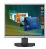
Owner's Manual (English)
Page 2
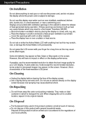
... a replacement. If the power cable is to allow the proper operation of power supply you leave the room for its installation, use, and servicing. If you use may result in any way, please contact the manufacturer or the nearest authorized repair service provider for an extended period of time. Call your personal safety, however improper use another power cord, make sure that it from the wall...
... a replacement. If the power cable is to allow the proper operation of power supply you leave the room for its installation, use, and servicing. If you use may result in any way, please contact the manufacturer or the nearest authorized repair service provider for an extended period of time. Call your personal safety, however improper use another power cord, make sure that it from the wall...
Owner's Manual (English)
Page 3
Important Precautions On Installation Do not allow the release of the fixed-resolution LCD panel. Therefore, NEVER: Block the bottom ventilation slots by placing the display on the display screen because over the power cord, and do not place the display where the power cord is provided. Place the display near water such as Red, Green or Blue spots on the screen. Some dot defects may appear as near...
Important Precautions On Installation Do not allow the release of the fixed-resolution LCD panel. Therefore, NEVER: Block the bottom ventilation slots by placing the display on the display screen because over the power cord, and do not place the display where the power cord is provided. Place the display near water such as Red, Green or Blue spots on the screen. Some dot defects may appear as near...
Owner's Manual (English)
Page 4
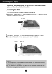
... carry the product upside down holding only the stand base. Once assembled take the monitor up the monitor, ensure that the power to the monitor, the computer system, and other attached devices is turned off. Assemble the Stand Base(Front, Rear) into the product in the correct direction as shown in the picture. Place the monitor with its front facing downward on a soft...
... carry the product upside down holding only the stand base. Once assembled take the monitor up the monitor, ensure that the power to the monitor, the computer system, and other attached devices is turned off. Assemble the Stand Base(Front, Rear) into the product in the correct direction as shown in the picture. Place the monitor with its front facing downward on a soft...
Owner's Manual (English)
Page 5
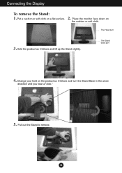
Connecting the Display To remove the Stand: 1. 2. Put a cushion or soft cloth on the cushion or soft cloth. Pull out the Stand to remove. Hold the product as it follows and lift up the Stand slightly. Change your hold on the product as it follows and turn the Stand Base in the arrow direction until you hear a "click." 5. A4 The Head part 3. Place the monitor face down on a flat surface. The Stand base part 4.
Connecting the Display To remove the Stand: 1. 2. Put a cushion or soft cloth on the cushion or soft cloth. Pull out the Stand to remove. Hold the product as it follows and lift up the Stand slightly. Change your hold on the product as it follows and turn the Stand Base in the arrow direction until you hear a "click." 5. A4 The Head part 3. Place the monitor face down on a flat surface. The Stand base part 4.
Owner's Manual (English)
Page 6
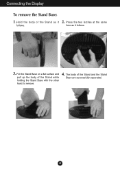
A5 Put the Stand Base on a flat surface and pull up the body of the Stand and the Stand Base are successfully separated. The body of the Stand while holding the Stand Base with the other hand. Connecting the Display To remove the Stand Base: 1.Hold the body of the Stand as it 2. Press the two latches at the same follows. to remove. 4. time as it follows. 3.
A5 Put the Stand Base on a flat surface and pull up the body of the Stand and the Stand Base are successfully separated. The body of the Stand while holding the Stand Base with the other hand. Connecting the Display To remove the Stand Base: 1.Hold the body of the Stand as it 2. Press the two latches at the same follows. to remove. 4. time as it follows. 3.
Owner's Manual (English)
Page 7
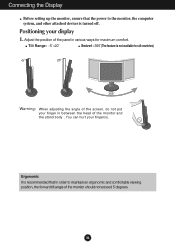
.... You can hurt your display 1. A6 Connecting the Display Before setting up the monitor, ensure that in between the head of the monitor and the stand body . Ergonomic It is recommended that the power to maintain an ergonomic and comfortable viewing position, the forward tilt angle of the monitor should not exceed 5 degrees. Adjust the position of the panel in various ways for all countries...
.... You can hurt your display 1. A6 Connecting the Display Before setting up the monitor, ensure that in between the head of the monitor and the stand body . Ergonomic It is recommended that the power to maintain an ergonomic and comfortable viewing position, the forward tilt angle of the monitor should not exceed 5 degrees. Adjust the position of the panel in various ways for all countries...
Owner's Manual (English)
Page 8
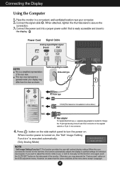
.... (Only Analog Mode) NOTE ' Self Image Setting Function'? Press button on the side switch panel to secure the connection. 3. When monitor power is turned on the OSD adjustment menu. Connect the signal cable 1 . This function provides the user with optimal display settings.When the user connects the monitor for the first time, this option initializes all countries.) PC MAC Mac adapter For Apple Macintosh use , or wish to a 15 pin 2 row connector. 4. However, be aware that is needed to change the...
.... (Only Analog Mode) NOTE ' Self Image Setting Function'? Press button on the side switch panel to secure the connection. 3. When monitor power is turned on the OSD adjustment menu. Connect the signal cable 1 . This function provides the user with optimal display settings.When the user connects the monitor for the first time, this option initializes all countries.) PC MAC Mac adapter For Apple Macintosh use , or wish to a 15 pin 2 row connector. 4. However, be aware that is needed to change the...
Owner's Manual (English)
Page 9
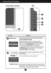
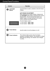
... changed. The default setting is used when two computers are connected to make D-Sub or DVI connector active. OSD LOCKED/UNLOCKED This function allows you to select or adjust functions in the On Screen Display. A8 Press and hold the MENU button for several seconds. The message "OSD LOCKED" should appear. For more information, refer to enter or exit the On Screen Display. Control Panel Functions Front Panel Controls Side Control MENU Button Function Use this button to the display...
... changed. The default setting is used when two computers are connected to make D-Sub or DVI connector active. OSD LOCKED/UNLOCKED This function allows you to select or adjust functions in the On Screen Display. A8 Press and hold the MENU button for several seconds. The message "OSD LOCKED" should appear. For more information, refer to enter or exit the On Screen Display. Control Panel Functions Front Panel Controls Side Control MENU Button Function Use this button to the display...
Owner's Manual (English)
Page 10
... On Screen Display(OSD). AUTO IMAGE ADJUSTMENT When adjusting your display image to amber. Power Indicator This Indicator lights up blue when the display operates normally(On Mode). A9 If the display is 17 inch monitor : 1280 x 1024 19 inch monitor : 1280 x 1024 Power Button Use this button to enter a selection in Sleep Mode (Energy Saving), this indicator color changes to the ideal settings for the current screen resolution size (display mode). Control Panel Functions Control AUTO/SET Button Function Use this button to turn the display on or off. The best display mode is...
... On Screen Display(OSD). AUTO IMAGE ADJUSTMENT When adjusting your display image to amber. Power Indicator This Indicator lights up blue when the display operates normally(On Mode). A9 If the display is 17 inch monitor : 1280 x 1024 19 inch monitor : 1280 x 1024 Power Button Use this button to enter a selection in Sleep Mode (Energy Saving), this indicator color changes to the ideal settings for the current screen resolution size (display mode). Control Panel Functions Control AUTO/SET Button Function Use this button to turn the display on or off. The best display mode is...
Owner's Manual (English)
Page 12
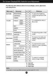
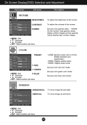
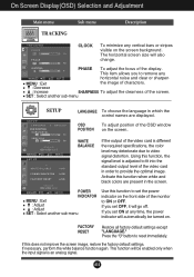
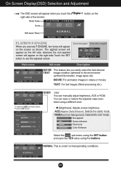
... control, adjustment, and setting menus. Main menu Sub-menu A D Reference PICTURE BRIGHTNESS CONTRAST GAMMA To adjust the brightness, contrast and gamma of the screen COLOR POSITION PRESET sRGB 6500K 9300K RED GREEN BLUE HORIZONTAL VERTICAL To customize the color of the screen To adjust the position of the screen CLOCK TRACKING PHASE SHARPNESS To improve the clarity and stability, sharpness of the screen SETUP LANGUAGE OSD HORIZONTAL POSITION VERTICAL To customize the screen status for a user's operating environment FLATRON F-ENGINE WHITE BALANCE POWER INDICATOR FACTORY RESET...
... control, adjustment, and setting menus. Main menu Sub-menu A D Reference PICTURE BRIGHTNESS CONTRAST GAMMA To adjust the brightness, contrast and gamma of the screen COLOR POSITION PRESET sRGB 6500K 9300K RED GREEN BLUE HORIZONTAL VERTICAL To customize the color of the screen To adjust the position of the screen CLOCK TRACKING PHASE SHARPNESS To improve the clarity and stability, sharpness of the screen SETUP LANGUAGE OSD HORIZONTAL POSITION VERTICAL To customize the screen status for a user's operating environment FLATRON F-ENGINE WHITE BALANCE POWER INDICATOR FACTORY RESET...
Owner's Manual (English)
Page 13
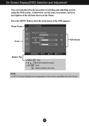
On Screen Display(OSD) Selection and Adjustment You were introduced to the procedure of the all items shown on the monitor may differ from the manual. A12 Menu Name PICTURE Icons Sub-menus Button Tip MENU : Exit : Adjust (Decrease/Increase) SET : Enter : Select another sub-menu NOTE OSD (On Screen Display) menu languages on the Menu. Listed below are the icons, icon names, and icon descriptions of selecting and adjusting an item using the OSD system. Press the MENU Button, then the main menu of the OSD appears.
On Screen Display(OSD) Selection and Adjustment You were introduced to the procedure of the all items shown on the monitor may differ from the manual. A12 Menu Name PICTURE Icons Sub-menus Button Tip MENU : Exit : Adjust (Decrease/Increase) SET : Enter : Select another sub-menu NOTE OSD (On Screen Display) menu languages on the Menu. Listed below are the icons, icon names, and icon descriptions of selecting and adjusting an item using the OSD system. Press the MENU Button, then the main menu of the OSD appears.
Owner's Manual (English)
Page 14
... bluish white. Set your own green color levels. Set your own blue color levels. COLOR COLOR PRESET RED GREEN MENU : Exit BLUE : Decrease : Increase SET : Select another sub-menu A13 Set your own gamma value. : -50/0/50 On the monitor, high gamma values display whitish images and low gamma values display high contrast images. POSITION POSITION HORIZONTAL VERTICAL To move image up and down. To move image left and right. On Screen Display(OSD) Selection and Adjustment Main menu Sub menu Description PICTURE PICTURE BRIGHTNESS CONTRAST GAMMA MENU : Exit...
... bluish white. Set your own green color levels. Set your own blue color levels. COLOR COLOR PRESET RED GREEN MENU : Exit BLUE : Decrease : Increase SET : Select another sub-menu A13 Set your own gamma value. : -50/0/50 On the monitor, high gamma values display whitish images and low gamma values display high contrast images. POSITION POSITION HORIZONTAL VERTICAL To move image up and down. To move image left and right. On Screen Display(OSD) Selection and Adjustment Main menu Sub menu Description PICTURE PICTURE BRIGHTNESS CONTRAST GAMMA MENU : Exit...
Owner's Manual (English)
Page 15
...-menu Use this function, the signal level is adjusted to fit into the standard output level of the video card in the screen. If you set OFF, it will also change. SETUP WHITE BALANCE If the output of the screen. Press the button to ON or OFF. Using this function to set the power indicator on the screen. Activate this does not improve the screen image, restore the factory default settings. The horizontal screen size...
...-menu Use this function, the signal level is adjusted to fit into the standard output level of the video card in the screen. If you set OFF, it will also change. SETUP WHITE BALANCE If the output of the screen. Press the button to ON or OFF. Using this function to set the power indicator on the screen. Activate this does not improve the screen image, restore the factory default settings. The horizontal screen size...
Owner's Manual (English)
Page 16
...: For text images (Word processing etc.) USER User You can save or restore the adjusted value even when using a different envir To adjust the USER sub-menu function, Press the SET Button USER BRIGHTNESS ACE 1 RCM 2 SAVE ... (Brightness): Adjusts screen brightness. ...ACE(Adaptive Clarity Enhancer): Selects the clarity mode. ...RCM(Real Color Management): Selects the color mode. 0 Not applied 1 Green enhance 2 Flesh tone 3 Color Enhance Select the SAVE sub-menu using the SET button and save the YES value using the buttons. NORMAL...
...: For text images (Word processing etc.) USER User You can save or restore the adjusted value even when using a different envir To adjust the USER sub-menu function, Press the SET Button USER BRIGHTNESS ACE 1 RCM 2 SAVE ... (Brightness): Adjusts screen brightness. ...ACE(Adaptive Clarity Enhancer): Selects the clarity mode. ...RCM(Real Color Management): Selects the color mode. 0 Not applied 1 Green enhance 2 Flesh tone 3 Color Enhance Select the SAVE sub-menu using the SET button and save the YES value using the buttons. NORMAL...
Owner's Manual (English)
Page 17
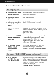
...; This message appears when the signal from the RANGE" message on the screen? power indicator blue or green? frequency range of the • Check and see a "OSD LOCKED" message on PC (video card) is out of this manual and configure your display is not connected. Check the signal cable and try moving the mouse or pressing any time by pushing the MENU button for service. A16 No image appears G Is the power cord of the...
...; This message appears when the signal from the RANGE" message on the screen? power indicator blue or green? frequency range of the • Check and see a "OSD LOCKED" message on PC (video card) is out of this manual and configure your display is not connected. Check the signal cable and try moving the mouse or pressing any time by pushing the MENU button for service. A16 No image appears G Is the power cord of the...
Owner's Manual (English)
Page 18
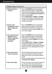
... adjust your display image to the ideal setting. G Any horizontal noise appearing in any image or characters are unsatisfactory, decrease the vertical bars or stripes using the PHASE icon in the on screen display. • Check Control Panel --> Display --> Settings and see if the frequency or the resolution were changed. Troubleshooting Display image is incorrect G Display Position is properly inserted in the on screen display. If yes, readjust the video card to the recommend resolution. • Make sure the power...
... adjust your display image to the ideal setting. G Any horizontal noise appearing in any image or characters are unsatisfactory, decrease the vertical bars or stripes using the PHASE icon in the on screen display. • Check Control Panel --> Display --> Settings and see if the frequency or the resolution were changed. Troubleshooting Display image is incorrect G Display Position is properly inserted in the on screen display. If yes, readjust the video card to the recommend resolution. • Make sure the power...
Owner's Manual (English)
Page 19
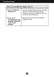
G Have you see an "Unrecognized monitor, Plug&Play (VESA DDC) monitor found" message? • Make sure to install the display driver from our web site: http://www.lge.com. A18 G Do you installed the display driver? • Be sure to check if the video card supports Plug&Play function. Or, you installed the display driver? Troubleshooting Have you can also download the driver from the display driver CD (or diskette) that comes with your display.
G Have you see an "Unrecognized monitor, Plug&Play (VESA DDC) monitor found" message? • Make sure to install the display driver from our web site: http://www.lge.com. A18 G Do you installed the display driver? • Be sure to check if the video card supports Plug&Play function. Or, you installed the display driver? Troubleshooting Have you can also download the driver from the display driver CD (or diskette) that comes with your display.
Owner's Manual (English)
Page 20
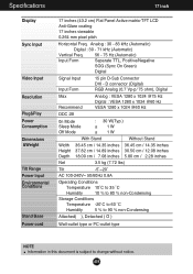
...is subject to change without notice. A19 Specifications 17 inch Display Sync Input Video Input Resolution Plug&Play Power Consumption Dimensions &Weight Tilt Range Power Input Environmental Conditions Stand Base Power cord 17 inches (43.2 cm) Flat Panel Active matrix-TFT LCD Anti-Glare coating 17 inches viewable 0.264 mm pixel pitch Horizontal Freq. Analog : 30 - 83 kHz (Automatic) Digital : 30 - 71 kHz (Automatic) Vertical Freq. 56 - 75 Hz (Automatic) Input Form Separate TTL, Positive/Negative SOG (Sync On Green) Digital Signal Input Input Form 15 pin D-Sub Connector DVI -
...is subject to change without notice. A19 Specifications 17 inch Display Sync Input Video Input Resolution Plug&Play Power Consumption Dimensions &Weight Tilt Range Power Input Environmental Conditions Stand Base Power cord 17 inches (43.2 cm) Flat Panel Active matrix-TFT LCD Anti-Glare coating 17 inches viewable 0.264 mm pixel pitch Horizontal Freq. Analog : 30 - 83 kHz (Automatic) Digital : 30 - 71 kHz (Automatic) Vertical Freq. 56 - 75 Hz (Automatic) Input Form Separate TTL, Positive/Negative SOG (Sync On Green) Digital Signal Input Input Form 15 pin D-Sub Connector DVI -
Owner's Manual (English)
Page 21
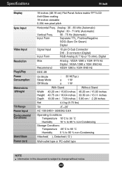
... subject to change without notice. A20 Specifications 19 inch Display Sync Input Video Input Resolution Plug&Play Power Consumption Dimensions &Weight Tilt Range Power Input Environmental Conditions Stand Base Power cord 19 inches (48.19 cm) Flat Panel Active matrix-TFT LCD Anti-Glare coating 19 inches viewable 0.294 mm pixel pitch Horizontal Freq. Analog : 30 - 83 kHz (Automatic) Digital : 30 - 71 kHz (Automatic) Vertical Freq. 56 - 75 Hz (Automatic) Input Form Separate TTL, Positive/Negative SOG (Sync On Green) Digital Signal Input Input Form 15 pin D-Sub Connector DVI -
... subject to change without notice. A20 Specifications 19 inch Display Sync Input Video Input Resolution Plug&Play Power Consumption Dimensions &Weight Tilt Range Power Input Environmental Conditions Stand Base Power cord 19 inches (48.19 cm) Flat Panel Active matrix-TFT LCD Anti-Glare coating 19 inches viewable 0.294 mm pixel pitch Horizontal Freq. Analog : 30 - 83 kHz (Automatic) Digital : 30 - 71 kHz (Automatic) Vertical Freq. 56 - 75 Hz (Automatic) Input Form Separate TTL, Positive/Negative SOG (Sync On Green) Digital Signal Input Input Form 15 pin D-Sub Connector DVI -
Owner's Manual (English)
Page 24
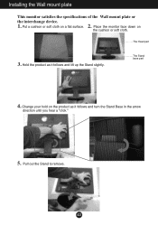
Installing the Wall mount plate This monitor satisfies the specifications of the Wall mount plate or the interchange device. 1. 2. The Head part 3. Hold the product as it follows and lift up the Stand slightly. Put a cushion or soft cloth on the cushion or soft cloth. The Stand base part 4. Pull out the Stand to remove. A23 Change your hold on the product as it follows and turn the Stand Base in the arrow direction until you hear a "click." 5. Place the monitor face down on a flat surface.
Installing the Wall mount plate This monitor satisfies the specifications of the Wall mount plate or the interchange device. 1. 2. The Head part 3. Hold the product as it follows and lift up the Stand slightly. Put a cushion or soft cloth on the cushion or soft cloth. The Stand base part 4. Pull out the Stand to remove. A23 Change your hold on the product as it follows and turn the Stand Base in the arrow direction until you hear a "click." 5. Place the monitor face down on a flat surface.


