

User Manual
Page 2
... you use another power cord, make sure that have in the specifications of time. Operate the display only from a power source indicated in your home, consult with the unit. Keep children from the wall outlet. Do not add accessories that it from dropping or pushing objects into the display's cabinet openings. A1 On Safety Use only the power cord supplied with your dealer. The power supply cord is faulty...
... you use another power cord, make sure that have in the specifications of time. Operate the display only from a power source indicated in your home, consult with the unit. Keep children from the wall outlet. Do not add accessories that it from dropping or pushing objects into the display's cabinet openings. A1 On Safety Use only the power cord supplied with your dealer. The power supply cord is faulty...

User Manual
Page 3
... the display on the screen. Place the display near a swimming pool. If used in this product contains a small amount of the fixed-resolution LCD panel. Use a slightly damp (not wet) cloth. They make an ideal container in which may result in accordance to transport the unit. Disposal of this may cause some scaled or processed images may cause electrical shock. Cover the openings...
... the display on the screen. Place the display near a swimming pool. If used in this product contains a small amount of the fixed-resolution LCD panel. Use a slightly damp (not wet) cloth. They make an ideal container in which may result in accordance to transport the unit. Disposal of this may cause some scaled or processed images may cause electrical shock. Cover the openings...

User Manual
Page 4
... the stand base to over 180 degrees. Place the monitor upright and adjust the stand base angle as desired. Adjust the stand base angle holding the monitor head part with slightly more force. folding the stand base 1.Face the front of connection. Your monitor may damage the stand base. Connecting the Display Before setting up the monitor, ensure that the power to the monitor screen while expanding or folding the stand base. Further expand the stand base to...
... the stand base to over 180 degrees. Place the monitor upright and adjust the stand base angle as desired. Adjust the stand base angle holding the monitor head part with slightly more force. folding the stand base 1.Face the front of connection. Your monitor may damage the stand base. Connecting the Display Before setting up the monitor, ensure that the power to the monitor screen while expanding or folding the stand base. Further expand the stand base to...

User Manual
Page 5
Separate the back cap by pushing upward. 4. Insert the back cap along the bottom grooves on both sides, holding the bottom. Connecting the Display Using the Computer 1. After the cables are connected, set the back cap into the groove of the upper section and reassemble by sliding its lower section downward as shown in the picture. 2. Connect the signal input cable and the power cord. (see next page) 3. A4
Separate the back cap by pushing upward. 4. Insert the back cap along the bottom grooves on both sides, holding the bottom. Connecting the Display Using the Computer 1. After the cables are connected, set the back cap into the groove of the upper section and reassemble by sliding its lower section downward as shown in the picture. 2. Connect the signal input cable and the power cord. (see next page) 3. A4

User Manual
Page 6
... the user connects the monitor for individual input signals. NOTE This is executed automatically. (Only Analog Mode) NOTE ' Self Image Setting Function'? Press button on the front panel of the rear view. When monitor power is turned on the supplied cable to secure the connection. 2. Power Cord Signal Cable Digital signal Analog signal Wall-outlet type 2 1 PC-outlet type PC PC MAC Mac adapter For Apple Macintosh use , or wish to the display. When attached, tighten the thumbscrews to a 15 pin 2 row connector...
... the user connects the monitor for individual input signals. NOTE This is executed automatically. (Only Analog Mode) NOTE ' Self Image Setting Function'? Press button on the front panel of the rear view. When monitor power is turned on the supplied cable to secure the connection. 2. Power Cord Signal Cable Digital signal Analog signal Wall-outlet type 2 1 PC-outlet type PC PC MAC Mac adapter For Apple Macintosh use , or wish to the display. When attached, tighten the thumbscrews to a 15 pin 2 row connector...
User Manual
Page 7
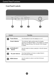
Control Panel Functions Front Panel Controls Control Function Power Button Power Indicator AUTO/SELECT Button Use this indicator color changes to amber. Buttons Use these buttons to enter or exit the On Screen Display. If the display is in Sleep Mode (Energy Saving), this button to enter a selection in the On Screen Display. MENU Button Use this button to turn the display on or off. A6 Use this button to choose or adjust items in the On Screen Display. This Indicator lights up blue when the display operates normally(On Mode).
Control Panel Functions Front Panel Controls Control Function Power Button Power Indicator AUTO/SELECT Button Use this indicator color changes to amber. Buttons Use these buttons to enter or exit the On Screen Display. If the display is in Sleep Mode (Energy Saving), this button to enter a selection in the On Screen Display. MENU Button Use this button to turn the display on or off. A6 Use this button to choose or adjust items in the On Screen Display. This Indicator lights up blue when the display operates normally(On Mode).

User Manual
Page 8
... "OSD LOCKED" appears. Control Panel Functions Control Direct Access Function AUTO IMAGE ADJUSTMENT When adjusting your display image to the ideal settings for the current screen resolution size (display mode).The best display mode is 17 inch monitor : 1280x1024 SOURCE To select DSUB ANALOG, DVI DIGITAL as the active input. The display automatically detects the proper input when only one video source is used when two computers are connected to the display. Press and hold the MENU button for 5 seconds: the message "OSD UNLOCKED" will automatically adjust your display settings, always...
... "OSD LOCKED" appears. Control Panel Functions Control Direct Access Function AUTO IMAGE ADJUSTMENT When adjusting your display image to the ideal settings for the current screen resolution size (display mode).The best display mode is 17 inch monitor : 1280x1024 SOURCE To select DSUB ANALOG, DVI DIGITAL as the active input. The display automatically detects the proper input when only one video source is used when two computers are connected to the display. Press and hold the MENU button for 5 seconds: the message "OSD UNLOCKED" will automatically adjust your display settings, always...

User Manual
Page 9
... Screen Display (OSD) Control Adjustment Screen Adjustment Making adjustments to the image size, position and operating parameters of the display is an outline of the available adjustments and selections you can make adjustments in the On Screen Display, follow these steps: Press the MENU Button, then the main menu of the controls. Use the Buttons to adjust the item to stabilize for at least 30 minutes before making image adjustments. The following section is quick and easy with the use...
... Screen Display (OSD) Control Adjustment Screen Adjustment Making adjustments to the image size, position and operating parameters of the display is an outline of the available adjustments and selections you can make adjustments in the On Screen Display, follow these steps: Press the MENU Button, then the main menu of the controls. Use the Buttons to adjust the item to stabilize for at least 30 minutes before making image adjustments. The following section is quick and easy with the use...
User Manual
Page 10
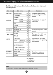
...Sub-menu A D Reference PICTURE BRIGHTNESS CONTRAST GAMMA COLOR PRESET 6500K 9300K RED GREEN POSITION BLUE HORIZONTAL VERTICAL TRACKING CLOCK PHASE To adjust the brightness, contrast and gamma of the screen To customize the color of the screen To adjust the position of the screen To improve the clarity and stability of the screen SETUP LANGUAGE OSD HORIZONTAL POSITION VERTICAL WHITE BALANCE POWER INDICATOR FACTORY RESET FLATRON MOVIE / TEXT F-ENGINE(- ) USER NORMAL To customize the screen status for a user's operating environment To select or customize desired image settings...
...Sub-menu A D Reference PICTURE BRIGHTNESS CONTRAST GAMMA COLOR PRESET 6500K 9300K RED GREEN POSITION BLUE HORIZONTAL VERTICAL TRACKING CLOCK PHASE To adjust the brightness, contrast and gamma of the screen To customize the color of the screen To adjust the position of the screen To improve the clarity and stability of the screen SETUP LANGUAGE OSD HORIZONTAL POSITION VERTICAL WHITE BALANCE POWER INDICATOR FACTORY RESET FLATRON MOVIE / TEXT F-ENGINE(- ) USER NORMAL To customize the screen status for a user's operating environment To select or customize desired image settings...

User Manual
Page 11
... the monitor may differ from the manual. CONTRAST To adjust the contrast of selecting and adjusting an item using the OSD system. A10 On Screen Display(OSD) Selection and Adjustment You were introduced to the procedure of the screen. MENU Vertical Position To move image left and right. Listed below are the icons, icon names, and icon descriptions of the screen OSD Adjust POSITION Description Horizontal Position To move image up and down. MENU RED GREEN Set your...
... the monitor may differ from the manual. CONTRAST To adjust the contrast of selecting and adjusting an item using the OSD system. A10 On Screen Display(OSD) Selection and Adjustment You were introduced to the procedure of the screen. MENU Vertical Position To move image left and right. Listed below are the icons, icon names, and icon descriptions of the screen OSD Adjust POSITION Description Horizontal Position To move image up and down. MENU RED GREEN Set your...

User Manual
Page 12
... when white and black colors are present in which the control names are displayed. POWER Use this does not improve the screen image, restore the factory default settings. If you to provide the optimal image. On Screen Display(OSD) Selection and Adjustment To improve the clarity and stability of the screen OSD Adjust TRACKING MENU CLOCK PHASE Description To minimize any vertical bars or stripes visible on the screen. A11 SETUP MENU MENU OSDPOSITION To adjust position of the OSD window...
... when white and black colors are present in which the control names are displayed. POWER Use this does not improve the screen image, restore the factory default settings. If you to provide the optimal image. On Screen Display(OSD) Selection and Adjustment To improve the clarity and stability of the screen OSD Adjust TRACKING MENU CLOCK PHASE Description To minimize any vertical bars or stripes visible on the screen. A11 SETUP MENU MENU OSDPOSITION To adjust position of the OSD window...

User Manual
Page 13
... adjusted value even when using the buttons. Screen when applied Screen when not applied Main menu Sub menu Description MOVIE This feature lets you touch the right side of the monitor. To adjust the USER sub-menu function, Press the SET Button (Brightness): Adjusts screen brightness. ACE(Adaptive Clarity Enhancer) Selects the clarity mode. On Screen Display(OSD) Selection and Adjustment The OSD screen will appear when you easily select the best desired TEXT image condition optimized to use the adjusted screen...
... adjusted value even when using the buttons. Screen when applied Screen when not applied Main menu Sub menu Description MOVIE This feature lets you touch the right side of the monitor. To adjust the USER sub-menu function, Press the SET Button (Brightness): Adjusts screen brightness. ACE(Adaptive Clarity Enhancer) Selects the clarity mode. On Screen Display(OSD) Selection and Adjustment The OSD screen will appear when you easily select the best desired TEXT image condition optimized to use the adjusted screen...

User Manual
Page 14
... you see "OSD LOCKED" when you see if the power cord is not connected. A13 If the display is out of horizontal or vertical frequency range of the display connected? Is the power indicator light on and the power indicator blue or green? Press the Power button. Check the signal cable and try moving the mouse or pressing any time by pushing the MENU button for service. You can secure the current control settings, so that they...
... you see "OSD LOCKED" when you see if the power cord is not connected. A13 If the display is out of horizontal or vertical frequency range of the display connected? Is the power indicator light on and the power indicator blue or green? Press the Power button. Check the signal cable and try moving the mouse or pressing any time by pushing the MENU button for service. You can secure the current control settings, so that they...

User Manual
Page 15
... the vertical bars or stripes using the CLOCK icon in the on screen display. The screen color is incorrect. Check Control Panel --> Display --> Settings and see if the frequency or the resolution were changed. If the results are not clearly portrayed. The screen blinks. Troubleshooting Display image is incorrect Display Position is mono or abnormal. If yes, readjust the video card to the ideal setting. Press the AUTO/SELECT button to automatically adjust your display image to the recommend resolution. Check...
... the vertical bars or stripes using the CLOCK icon in the on screen display. The screen color is incorrect. Check Control Panel --> Display --> Settings and see if the frequency or the resolution were changed. If the results are not clearly portrayed. The screen blinks. Troubleshooting Display image is incorrect Display Position is mono or abnormal. If yes, readjust the video card to the ideal setting. Press the AUTO/SELECT button to automatically adjust your display image to the recommend resolution. Check...

User Manual
Page 16
... check if the video card supports Plug&Play function. Or, you see an "Unrecognized monitor, Plug&Play (VESA DDC) monitor found" message? Troubleshooting Have you installed the display driver? Do you can also download the driver from the display driver CD (or diskette) that comes with your display. For verification of USB support, consult the manufacturer of each system. Check if the PC and OS are USB compliant. Check if the USB cable is correctly connected...
... check if the video card supports Plug&Play function. Or, you see an "Unrecognized monitor, Plug&Play (VESA DDC) monitor found" message? Troubleshooting Have you installed the display driver? Do you can also download the driver from the display driver CD (or diskette) that comes with your display. For verification of USB support, consult the manufacturer of each system. Check if the PC and OS are USB compliant. Check if the USB cable is correctly connected...

User Manual
Page 17
... Display Sync Input Video Input Resolution Plug&Play Power Consumption Dimensions &Weight (with tilt stand) 17 inches (43.2 cm) Flat Panel Active matrix-TFT LCD Anti-Glare coating 17 inches viewable 0.264 mm pixel pitch Horizontal Freq. Analog : 30 - 83 kHz (Automatic) Digital : 30 - 71kHz (Automatic) Vertical Freq. 56 - 75Hz (Automatic) Input Form Separate TTL, Positive/Negative SOG (Sync On Green) Digital Signal Input Input Form 15 pin D-Sub Connector DVI-D connector (Digital) RGB Analog (0.7Vp-p/75ohm), Digital Max Recommend DVI Digital: VESA 1280 x 1024 @60Hz D-sub Analog: VESA...
... Display Sync Input Video Input Resolution Plug&Play Power Consumption Dimensions &Weight (with tilt stand) 17 inches (43.2 cm) Flat Panel Active matrix-TFT LCD Anti-Glare coating 17 inches viewable 0.264 mm pixel pitch Horizontal Freq. Analog : 30 - 83 kHz (Automatic) Digital : 30 - 71kHz (Automatic) Vertical Freq. 56 - 75Hz (Automatic) Input Form Separate TTL, Positive/Negative SOG (Sync On Green) Digital Signal Input Input Form 15 pin D-Sub Connector DVI-D connector (Digital) RGB Analog (0.7Vp-p/75ohm), Digital Max Recommend DVI Digital: VESA 1280 x 1024 @60Hz D-sub Analog: VESA...
User Manual
Page 18
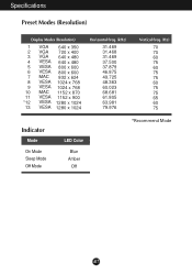
Specifications Preset Modes (Resolution) Display Modes (Resolution) 1 VGA 640 x 350 2 VGA 720 x 400 3 VGA 640 x 480 4 VESA 640 x 480 5 VESA 800 x 600 6 VESA 800 x 600 7 MAC 832 x 624 8 VESA 1024 x 768 9 VESA 1024 x 768 10 MAC 1152 x 870 11 VESA 1152 x 900 *12 VESA 1280 x 1024 13 VESA 1280 x 1024 Horizontal Freq. (kHz) 31.469 31.468 31.469 37.500 37.879 46.875 49.725 48.363 60.023 68.681 61.805 63.981 79.976 Vertical Freq. (Hz) 70 70 60 75 60 75 75 60 75 75 65 60 75 Indicator Mode On Mode Sleep Mode Off Mode LED Color Blue Amber Off *Recommend Mode A17
Specifications Preset Modes (Resolution) Display Modes (Resolution) 1 VGA 640 x 350 2 VGA 720 x 400 3 VGA 640 x 480 4 VESA 640 x 480 5 VESA 800 x 600 6 VESA 800 x 600 7 MAC 832 x 624 8 VESA 1024 x 768 9 VESA 1024 x 768 10 MAC 1152 x 870 11 VESA 1152 x 900 *12 VESA 1280 x 1024 13 VESA 1280 x 1024 Horizontal Freq. (kHz) 31.469 31.468 31.469 37.500 37.879 46.875 49.725 48.363 60.023 68.681 61.805 63.981 79.976 Vertical Freq. (Hz) 70 70 60 75 60 75 75 60 75 75 65 60 75 Indicator Mode On Mode Sleep Mode Off Mode LED Color Blue Amber Off *Recommend Mode A17
User Manual
Page 20
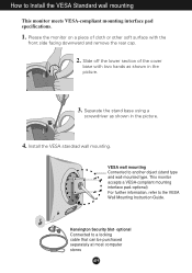
... wall-mounted type. Please the monitor on a piece of the cover base with the front side facing downward and remove the rear cap. 2. Separate the stand base using a screwdriver as shown in the picture. 4. How to a locking cable that can be purchased separately at most computer stores A19 Install the VESA standrad wall mounting. Kensington Security Slot- optional Connected to Install the VESA Standard wall mounting This monitor meets VESA-compliant mounting interface pad specifications...
... wall-mounted type. Please the monitor on a piece of the cover base with the front side facing downward and remove the rear cap. 2. Separate the stand base using a screwdriver as shown in the picture. 4. How to a locking cable that can be purchased separately at most computer stores A19 Install the VESA standrad wall mounting. Kensington Security Slot- optional Connected to Install the VESA Standard wall mounting This monitor meets VESA-compliant mounting interface pad specifications...

User Manual
Page 21
... another hub with the USB cable(enclosed). Making use of up to 2 other peripherals to your system. This display has an integrated BUSpowered USB hub, allowing up to connect them while maintaining the Plug and the Plug auto detection and configuration. USB upstream Port To USB downstream port of having to 120 devices on a single USB port; Optional USB (Universal Serial Bus) is in a power saving mode, USB compliant devices will give...
... another hub with the USB cable(enclosed). Making use of up to 2 other peripherals to your system. This display has an integrated BUSpowered USB hub, allowing up to connect them while maintaining the Plug and the Plug auto detection and configuration. USB upstream Port To USB downstream port of having to 120 devices on a single USB port; Optional USB (Universal Serial Bus) is in a power saving mode, USB compliant devices will give...

User Manual
Page 22
LGE recommends connecting high-power USB devices directly to the computer A21 Optional USB Specifications USB standard Downstream power supply Communication speed USB port Rev. 1.1 complied BUS-powered hub 100mA for each (MAX) 12 Mbps (full), 1.5 Mbps (low) 1 Upstream port 2 Downstream ports IMPORTANT: These USB connectors are not designed for use of USB (Universal Serial Bus) - Making use with high-power USB devices such as a video camera, scanner, etc.
LGE recommends connecting high-power USB devices directly to the computer A21 Optional USB Specifications USB standard Downstream power supply Communication speed USB port Rev. 1.1 complied BUS-powered hub 100mA for each (MAX) 12 Mbps (full), 1.5 Mbps (low) 1 Upstream port 2 Downstream ports IMPORTANT: These USB connectors are not designed for use of USB (Universal Serial Bus) - Making use with high-power USB devices such as a video camera, scanner, etc.


