
Service Manual
Page 1
MODEL : DLE8377WM/DLG8388WM DLE8377NM/DLG8388NM DLE7177WM/DLG7188WM U.S.A. Website: http://us.lgservice.com Canadian Website: http://lg.ca ELECTRIC & GAS DRYER SERVICE MANUAL CAUTION READ THIS MANUAL CAREFULLY IN ORDER TO PROPERLY DIAGNOSE PROBLEMS AND TO SAFELY PROVIDE QUALITY SERVICE ON THESE DRYERS.
MODEL : DLE8377WM/DLG8388WM DLE8377NM/DLG8388NM DLE7177WM/DLG7188WM U.S.A. Website: http://us.lgservice.com Canadian Website: http://lg.ca ELECTRIC & GAS DRYER SERVICE MANUAL CAUTION READ THIS MANUAL CAREFULLY IN ORDER TO PROPERLY DIAGNOSE PROBLEMS AND TO SAFELY PROVIDE QUALITY SERVICE ON THESE DRYERS.
Service Manual
Page 3
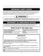
... turn on any electrical switches. Do not use any liability in connection with its package, touch the anti-static bag to a green ground connection point or unpainted metal in anti-static bag, observe above instructions. 2 If you cannot reach your gas supplier, call your building. Avoid touching electronic parts or terminal contacts; IMPORTANT SAFETY NOTICE The information in this service guide is...
... turn on any electrical switches. Do not use any liability in connection with its package, touch the anti-static bag to a green ground connection point or unpainted metal in anti-static bag, observe above instructions. 2 If you cannot reach your gas supplier, call your building. Avoid touching electronic parts or terminal contacts; IMPORTANT SAFETY NOTICE The information in this service guide is...

Service Manual
Page 4
...9-2. TEST 6 HEATER SWITCH TEST - ELECTRIC MODEL 27 9-7. CHANGE GAS SETTING (NATURAL GAS, PROPANE GAS 30 11. EXPLODED VIEW ...39 12-1. SPECIFICATIONS ...4 2. TEST 2 THERMISTOR TEST 22 9-3. GAS MODEL 28 9-8 TEST 8 SEMI-CONDUCTOR 29 10. COMPONENT TESTING INFORMATION 14 6. TEST 5 DOOR SWITCH TEST 26 9-6. CABINET & DOOR ASSEMBLY 40 12-3-1. MOTOR DIAGRAM AND SCHEMATIC 17 7. CONTROL PANEL & PLATE ASSEMBLY 39 12-2. DRUM & MOTOR ASSEMBLY: GAS MODEL 42 13. DRYER CYCLE PROCESS ...13 5. TEST 3 MOTOR TEST 24 9-4. TEST 7 GAS VALVE TEST - REPLACEMENT PARTS LIST 43...
...9-2. TEST 6 HEATER SWITCH TEST - ELECTRIC MODEL 27 9-7. CHANGE GAS SETTING (NATURAL GAS, PROPANE GAS 30 11. EXPLODED VIEW ...39 12-1. SPECIFICATIONS ...4 2. TEST 2 THERMISTOR TEST 22 9-3. GAS MODEL 28 9-8 TEST 8 SEMI-CONDUCTOR 29 10. COMPONENT TESTING INFORMATION 14 6. TEST 5 DOOR SWITCH TEST 26 9-6. CABINET & DOOR ASSEMBLY 40 12-3-1. MOTOR DIAGRAM AND SCHEMATIC 17 7. CONTROL PANEL & PLATE ASSEMBLY 39 12-2. DRUM & MOTOR ASSEMBLY: GAS MODEL 42 13. DRYER CYCLE PROCESS ...13 5. TEST 3 MOTOR TEST 24 9-4. TEST 7 GAS VALVE TEST - REPLACEMENT PARTS LIST 43...
Service Manual
Page 6
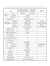
... No. of Programs No. of Dry Levels Sound levels Sensor Moisture Temperature Reversible Door Drum Dryer Rack Child Lock Interior Light Product (WxHxD) Packing (WxHxD) Blue White Navy Blue... 3/4" x 30 3/4" REMARK AC 120V AC 240V (ELECTRIC MODEL) AC 120V AC 120V (GAS MODEL) Electrode sensor Thermistor 5 Net/Gross No. of Temperature Controls No. ITEM DLE7177WM/DLE8377WM DLE8377NM DLG7188WM/DLG8388WM DLG8388NM Material & Finish Color Top Plate Door Trim POWER SUPPLY ELECTRICITY CONSUMPTION MOTOR HEATER LAMP GAS VALVE CONTROL TYPE DRUM CAPACITY Weight (lbs) -
... No. of Programs No. of Dry Levels Sound levels Sensor Moisture Temperature Reversible Door Drum Dryer Rack Child Lock Interior Light Product (WxHxD) Packing (WxHxD) Blue White Navy Blue... 3/4" x 30 3/4" REMARK AC 120V AC 240V (ELECTRIC MODEL) AC 120V AC 120V (GAS MODEL) Electrode sensor Thermistor 5 Net/Gross No. of Temperature Controls No. ITEM DLE7177WM/DLE8377WM DLE8377NM DLG7188WM/DLG8388WM DLG8388NM Material & Finish Color Top Plate Door Trim POWER SUPPLY ELECTRICITY CONSUMPTION MOTOR HEATER LAMP GAS VALVE CONTROL TYPE DRUM CAPACITY Weight (lbs) -
Service Manual
Page 8
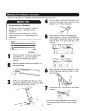
... required to lift and position the dryer on the side bracket. 6 Insert the front rail of the bracket. Slide the dryer back against the stops on the back of the stacking kit. Failure to heed this alone! 4 Secure the side bracket to the washer ...Screw both sides of a washing machine! Stacking Kit Installation Instructions To ensure safe and secure installation, please observe the instructions below. WARNING Do not attempt this warning can result in serious physical injury and damage to the side brackets. • Do not use a stacking kit with a gas dryer in the owner's manual.
... required to lift and position the dryer on the side bracket. 6 Insert the front rail of the bracket. Slide the dryer back against the stops on the back of the stacking kit. Failure to heed this alone! 4 Secure the side bracket to the washer ...Screw both sides of a washing machine! Stacking Kit Installation Instructions To ensure safe and secure installation, please observe the instructions below. WARNING Do not attempt this warning can result in serious physical injury and damage to the side brackets. • Do not use a stacking kit with a gas dryer in the owner's manual.
Service Manual
Page 10
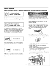
... be connecting box to a fused(21d.5"icsmc)onnect or circuit breaker (12.75c" m) 1. After cutting 11/2 inch (3.8cm) from end. Connect red and black wire to center terminal block screw. 2. peel insulation back 1inch (2.5cm). Make ends of 3 wires a hook shape. 1" (2.5 cm) (12.75c" m) ( Then, put the hooked shape end of covering m(a8t.36e1/c2r"mia) l from 3 other wires. and be replaced. Electric Dryer Only Review the...
... be connecting box to a fused(21d.5"icsmc)onnect or circuit breaker (12.75c" m) 1. After cutting 11/2 inch (3.8cm) from end. Connect red and black wire to center terminal block screw. 2. peel insulation back 1inch (2.5cm). Make ends of 3 wires a hook shape. 1" (2.5 cm) (12.75c" m) ( Then, put the hooked shape end of covering m(a8t.36e1/c2r"mia) l from 3 other wires. and be replaced. Electric Dryer Only Review the...
Service Manual
Page 11
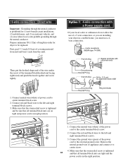
.... 4. Remove the neutral ground wire of appliance and connect it to the left and right terminal block screws. 3. 3-wire connection : Direct wire Important : Grounding through the neutral conductor is tightened 10 and that all terminal block nuts are installing your local codes or ordinances do not allow the use of a 3 wire connection, or you must use a 4wire connection. 1. Option 1: 4-wire connection with a Power supply cord. • lf your dryer in order for (1) new branch-circuit installations...
.... 4. Remove the neutral ground wire of appliance and connect it to the left and right terminal block screws. 3. 3-wire connection : Direct wire Important : Grounding through the neutral conductor is tightened 10 and that all terminal block nuts are installing your local codes or ordinances do not allow the use of a 3 wire connection, or you must use a 4wire connection. 1. Option 1: 4-wire connection with a Power supply cord. • lf your dryer in order for (1) new branch-circuit installations...
Service Manual
Page 12
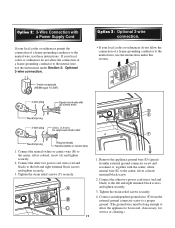
... service or cleaning.) Remove the appliance ground wire (D) (green) fromthe external ground connector screw and reconnect it, together with a Power Supply Cord lf your local codes or ordinances permit the connection of a frame-grounding conductor to the neutral wire, use the instructions under Section 3: Optional 3-wire connection. Connect the neutral (white or center) wire (B) to the center, silver colored, screw (A) and tighten securely. 2. Connect the other two power cord wires...
... service or cleaning.) Remove the appliance ground wire (D) (green) fromthe external ground connector screw and reconnect it, together with a Power Supply Cord lf your local codes or ordinances permit the connection of a frame-grounding conductor to the neutral wire, use the instructions under Section 3: Optional 3-wire connection. Connect the neutral (white or center) wire (B) to the center, silver colored, screw (A) and tighten securely. 2. Connect the other two power cord wires...

Service Manual
Page 13
...) for checking inlet gas pressure) 3 Equipment Shut-Off Valve-Installed within 6' (1.8 m) of dryer 4 Black Iron Pipe Shorter than 20' (6.1 m) - Pipe Plug (for gas leaks with a non-corrosive leak detection fluid. 5. Make certain your dryer is equipped at the rear of gas in your laundry room. Connect to section on Gas Requirements. 1 2 5 3 4 1 New Stainless Steel Flexible Connector - Gas Connection 12 Dryer is equipped for Natural Gas with the type of the dryer. Use only...
...) for checking inlet gas pressure) 3 Equipment Shut-Off Valve-Installed within 6' (1.8 m) of dryer 4 Black Iron Pipe Shorter than 20' (6.1 m) - Pipe Plug (for gas leaks with a non-corrosive leak detection fluid. 5. Make certain your dryer is equipped at the rear of gas in your laundry room. Connect to section on Gas Requirements. 1 2 5 3 4 1 New Stainless Steel Flexible Connector - Gas Connection 12 Dryer is equipped for Natural Gas with the type of the dryer. Use only...
Service Manual
Page 20
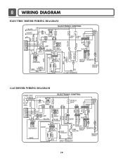
... RED YELLOW BLUE BROWN BROWN 8 7 6 5 4 3 2 1 COM LAMP 1 2 YELLOW NO GRAY 1 2 3 BELT SWITCH NC 123 1 2 3 7 10 MOTOR WHITE DOOR SWITCH OVERLOAD PROTECTOR BLUE ORANGE RED BLUE HEATER 2 1 2 1 MOISTURE THERMISTOR SENSOR RED SAFETY THERMOSTAT OUTER COIL INNER COIL CENTRIFUGAL SWITCH BLOWER WHITE THERMOSTAT RED RED HI - LIMIT THERMOSTAT MOISTURE SENSOR GAS DRYER WIRING DIAGRAM POWER CORD ELECTRONIC CONTROL L1 BLACK N WHITE GN/YL 1 WH1 TRANS 12 BL2 TAP RELAY...
... RED YELLOW BLUE BROWN BROWN 8 7 6 5 4 3 2 1 COM LAMP 1 2 YELLOW NO GRAY 1 2 3 BELT SWITCH NC 123 1 2 3 7 10 MOTOR WHITE DOOR SWITCH OVERLOAD PROTECTOR BLUE ORANGE RED BLUE HEATER 2 1 2 1 MOISTURE THERMISTOR SENSOR RED SAFETY THERMOSTAT OUTER COIL INNER COIL CENTRIFUGAL SWITCH BLOWER WHITE THERMOSTAT RED RED HI - LIMIT THERMOSTAT MOISTURE SENSOR GAS DRYER WIRING DIAGRAM POWER CORD ELECTRONIC CONTROL L1 BLACK N WHITE GN/YL 1 WH1 TRANS 12 BL2 TAP RELAY...
Service Manual
Page 21
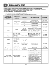
... Factory test /Service test. Displays Moisture Sensor Operation: If moisture sensor is contacted with the Door open may trip the Thermostat attached to the Heater, therefore do not activate it manually. (Do not press the door switch to the step 4. • Press Start 3 times and then open the door. Gas valve See test 7 See test 8 Auto Off See test 6 20 Activating the Heater manually with damp cloth. Current Temp. (5 ~ 70) ELECTRIC TYPE: Heater runs GAS TYPE: GAS Valve runs (Display the Temperature of Inside drum.) 4 times Motor, Heater...
... Factory test /Service test. Displays Moisture Sensor Operation: If moisture sensor is contacted with the Door open may trip the Thermostat attached to the Heater, therefore do not activate it manually. (Do not press the door switch to the step 4. • Press Start 3 times and then open the door. Gas valve See test 7 See test 8 Auto Off See test 6 20 Activating the Heater manually with damp cloth. Current Temp. (5 ~ 70) ELECTRIC TYPE: Heater runs GAS TYPE: GAS Valve runs (Display the Temperature of Inside drum.) 4 times Motor, Heater...
Service Manual
Page 22
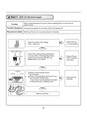
...? Connector linked to the Controller and WH1(White Wire) Is 110~125V? Check if Terminal Block and Power Cord are connected (Check Plug ). Does Power Cord N (Natural) line match to and avoid an electric shock. YES Replace controIler. 21 NO • Check the fuse or circuit breaker. • Check if Power NO Cord is properly connected. Test 1 120V AC Electrical supply Caution When measuring power, be sure to wear insulated gloves, to Terminal Center N (Natural) line? • Reconnect the controller. Trouble Symptom No power...
...? Connector linked to the Controller and WH1(White Wire) Is 110~125V? Check if Terminal Block and Power Cord are connected (Check Plug ). Does Power Cord N (Natural) line match to and avoid an electric shock. YES Replace controIler. 21 NO • Check the fuse or circuit breaker. • Check if Power NO Cord is properly connected. Test 1 120V AC Electrical supply Caution When measuring power, be sure to wear insulated gloves, to Terminal Center N (Natural) line? • Reconnect the controller. Trouble Symptom No power...

Service Manual
Page 25
... Thermistor assembly Connector. • Replace Thermistor. YES • Check if Control and the 6 pin connector are properly connected. • Replace Controller. Table 1. Short with metal to the 6 pin connector's Pin (Blue Wire) and Pin (Orange Wire) to turn off , measure the resistance. Resistance for Thermistor Temperature. Test 2 Thermistor Test --- Measure with the Ground.) Trouble Symptom During Diagnostic Test, tE1 and tE2 Error occur. Difference between actual and sensed temperature is in the range of Power cord...
... Thermistor assembly Connector. • Replace Thermistor. YES • Check if Control and the 6 pin connector are properly connected. • Replace Controller. Table 1. Short with metal to the 6 pin connector's Pin (Blue Wire) and Pin (Orange Wire) to turn off , measure the resistance. Resistance for Thermistor Temperature. Test 2 Thermistor Test --- Measure with the Ground.) Trouble Symptom During Diagnostic Test, tE1 and tE2 Error occur. Difference between actual and sensed temperature is in the range of Power cord...
Service Manual
Page 26
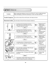
... metal plug of Outlet Thermostat attached to turn Power off from Motor Pulley. • Replace Idler Switch. • Check Motor. (Refer to Motor Bracket operate Level by drum belt? NO YES Does Idle Switch attached to 'Motor Diagram & Check') • Check if Control Connector is closed . Measure while door is contacted. 25 Measure while door is normal.) Is resistance below 3Ω between terminals of Power cord with earth line.) Trouble Symptom Drum will not rotate; YES (Not operating Lever...
... metal plug of Outlet Thermostat attached to turn Power off from Motor Pulley. • Replace Idler Switch. • Check Motor. (Refer to Motor Bracket operate Level by drum belt? NO YES Does Idle Switch attached to 'Motor Diagram & Check') • Check if Control Connector is closed . Measure while door is contacted. 25 Measure while door is normal.) Is resistance below 3Ω between terminals of Power cord with earth line.) Trouble Symptom Drum will not rotate; YES (Not operating Lever...

Service Manual
Page 27
... Harness Connector. • Check Harnesslinking connector. • Replace Control and Check. Short with Dry Level. Measurement Condition Turn the Dryer's Power Off, then measure resistance. Test 4 Moisture sensor Caution Before measuring resistance, be sure to turn Power off, and do voltage discharge. (When discharging, contact the metal plug of Power cord with earth line.) Trouble Symptom Degree of dryness does not match with metal to the 6 pin connector's Pin (Blue Wire...
... Harness Connector. • Check Harnesslinking connector. • Replace Control and Check. Short with Dry Level. Measurement Condition Turn the Dryer's Power Off, then measure resistance. Test 4 Moisture sensor Caution Before measuring resistance, be sure to turn Power off, and do voltage discharge. (When discharging, contact the metal plug of Power cord with earth line.) Trouble Symptom Degree of dryness does not match with metal to the 6 pin connector's Pin (Blue Wire...

Service Manual
Page 28
... metal plug of Power cord with earth line.) Door Opening is not sensed.(During operation, when opening Lamp, replace then measure again.) • Door switch Check(Refer to Component testing.) Measure while Door is open . Connector WH1,BL2 after taking Connector WH1,BL2 out from Controller. YES • Door switch Check (Refer to Component testing.) • Check Lamp. (When opening Door, Drum motor and Trouble Symptom Heater run continuously) Door Close is not sensed. (Drum motor will flash at 0.5 second intervals.) Measurement Condition After turning Dryer Power...
... metal plug of Power cord with earth line.) Door Opening is not sensed.(During operation, when opening Lamp, replace then measure again.) • Door switch Check(Refer to Component testing.) Measure while Door is open . Connector WH1,BL2 after taking Connector WH1,BL2 out from Controller. YES • Door switch Check (Refer to Component testing.) • Check Lamp. (When opening Door, Drum motor and Trouble Symptom Heater run continuously) Door Close is not sensed. (Drum motor will flash at 0.5 second intervals.) Measurement Condition After turning Dryer Power...

Service Manual
Page 29
...Ω? 2. NO YES • Replace TH3 (HI-Limit Thermostat). Check Harness-linking Connector. 28 Check if the value of Power cord with earth line.) Trouble Symptom While operating, Heating will not work. YES Check Controller. Electric Type Caution Before measuring resistance, be sure to turn Power off , measure the resistance. Is resistance between Heater terminal and below 9 ~ 11Ω? NO • Replace Heater. Is resistance between Heater terminal and below 18 ~ 22Ω...
...Ω? 2. NO YES • Replace TH3 (HI-Limit Thermostat). Check Harness-linking Connector. 28 Check if the value of Power cord with earth line.) Trouble Symptom While operating, Heating will not work. YES Check Controller. Electric Type Caution Before measuring resistance, be sure to turn Power off , measure the resistance. Is resistance between Heater terminal and below 9 ~ 11Ω? NO • Replace Heater. Is resistance between Heater terminal and below 18 ~ 22Ω...
Service Manual
Page 32
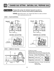
.... Propane Gas Orifice is set. Initially, Natural Gas mode is on sale as a Service Part to authorized servicers only. Replace Natural Gas orifice with Propane Gas orifice. Gas type Orifice P/No Marking Shape Natural Gas 4948EL4001B NCU Propane Gas 4948EL4002B PCU Kit contents: Orifice (Dia. = 1.613mm, for Propane Gas) Replace Label Instruction Sheet 31 Warning Changing orifices and gas valve adjustments improperly can result in an explosion and/or fire. Conversion must be made by a qualified technician. Disassemble the pipe assembly.
.... Propane Gas Orifice is set. Initially, Natural Gas mode is on sale as a Service Part to authorized servicers only. Replace Natural Gas orifice with Propane Gas orifice. Gas type Orifice P/No Marking Shape Natural Gas 4948EL4001B NCU Propane Gas 4948EL4002B PCU Kit contents: Orifice (Dia. = 1.613mm, for Propane Gas) Replace Label Instruction Sheet 31 Warning Changing orifices and gas valve adjustments improperly can result in an explosion and/or fire. Conversion must be made by a qualified technician. Disassemble the pipe assembly.
Service Manual
Page 45
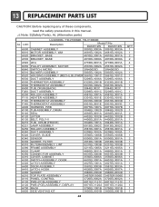
... 4986EL2004D 4986EL2004D 3457ER1006E 3457ER1006E A110 PANEL, CONTROL A130 PWB (PCB) ASSEMBLY 3720EL0002A 3720EL0002A 6871EC1121C 6871EC1121C A120 PWB (PCB) ASSEMBLY, DISPLAY A700 RACK A800 SIDE VENTING KIT 6871EC1120A 6871EC1120A 3750EL1001B 3750EL1001B 383EEL9001B 383EEL9001B 44 QTY 1 1 2 2 4 1 1 1 1 1 1 1 1 1 2 1 1 1 1 1 2 3 1 1 1 2 1 1 2 1 1 1 2 1 1 1 1 1 1 1 1 1 1 1 1 1 13 REPLACEMENT PARTS LIST CAUTION: Before replacing any of these components, read the safety precautions in this manual. ¡Æ Note: S(Safety Parts), AL (Alternative parts) LG MODEL: TD-V10062E, TD-V10060E...
... 4986EL2004D 4986EL2004D 3457ER1006E 3457ER1006E A110 PANEL, CONTROL A130 PWB (PCB) ASSEMBLY 3720EL0002A 3720EL0002A 6871EC1121C 6871EC1121C A120 PWB (PCB) ASSEMBLY, DISPLAY A700 RACK A800 SIDE VENTING KIT 6871EC1120A 6871EC1120A 3750EL1001B 3750EL1001B 383EEL9001B 383EEL9001B 44 QTY 1 1 2 2 4 1 1 1 1 1 1 1 1 1 2 1 1 1 1 1 2 3 1 1 1 2 1 1 2 1 1 1 2 1 1 1 1 1 1 1 1 1 1 1 1 1 13 REPLACEMENT PARTS LIST CAUTION: Before replacing any of these components, read the safety precautions in this manual. ¡Æ Note: S(Safety Parts), AL (Alternative parts) LG MODEL: TD-V10062E, TD-V10060E...
Service Manual
Page 46
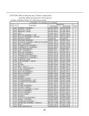
... 4986EL2004D A210 TOP PLATE ASSEMBLY 3457ER1006E 3457ER1006E A110 PANEL, CONTROL 3720EL0002A 3720EL0002A A130 PWB(PCB) ASSEMBLY 6871EC1121D 6871EC1121D A120 PWB(PCB) ASSEMBLY, DISPLAY 6871EC1120B 6871EC1120B A700 RACK 3750EL1001B 3750EL1001B A800 SIDE VENTING KIT 383EEL9001B 383EEL9001B 45 QTY 1 2 2 4 1 1 1 1 1 1 1 1 1 1 2 1 1 1 1 1 2 3 1 1 1 2 1 1 2 1 1 1 2 1 1 1 1 1 1 1 1 1 1 1 1 1 CAUTION: Before replacing any of these components, read the safety precautions in this manual. ¡Æ Note: S(Safety Parts), AL (Alternative parts) LG MODEL: TD-V10062G,TD...
... 4986EL2004D A210 TOP PLATE ASSEMBLY 3457ER1006E 3457ER1006E A110 PANEL, CONTROL 3720EL0002A 3720EL0002A A130 PWB(PCB) ASSEMBLY 6871EC1121D 6871EC1121D A120 PWB(PCB) ASSEMBLY, DISPLAY 6871EC1120B 6871EC1120B A700 RACK 3750EL1001B 3750EL1001B A800 SIDE VENTING KIT 383EEL9001B 383EEL9001B 45 QTY 1 2 2 4 1 1 1 1 1 1 1 1 1 1 2 1 1 1 1 1 2 3 1 1 1 2 1 1 2 1 1 1 2 1 1 1 1 1 1 1 1 1 1 1 1 1 CAUTION: Before replacing any of these components, read the safety precautions in this manual. ¡Æ Note: S(Safety Parts), AL (Alternative parts) LG MODEL: TD-V10062G,TD...


