

Owner's Manual
Page 1
Record model number and serial number of the set . P/NO : 38289U0577P (0711-REV06) Printed in Korea http://www.lge.com http://ar.lge.com LCD TV OWNER'S MANUAL LCD TV MODELS 37LC2RR 42LC2RR Please read this information to your set . See the label attached on the back cover and quote this manual carefully before operating your dealer when you require service. Retain it for future reference.
Record model number and serial number of the set . P/NO : 38289U0577P (0711-REV06) Printed in Korea http://www.lge.com http://ar.lge.com LCD TV OWNER'S MANUAL LCD TV MODELS 37LC2RR 42LC2RR Please read this information to your set . See the label attached on the back cover and quote this manual carefully before operating your dealer when you require service. Retain it for future reference.

Owner's Manual
Page 6
... 1-3 INTRODUCTION Accessories 6 Home Menu 7 Controls / Connection Options 8-9 Remote Control Key Functions 10-11 INSTALLATION Wire Arrangement 12 Attaching the TV to a Wall 13 Desktop Pedestal Installation 13 CONNECTIONS & SETUP Antenna Connection 14 VCR Setup 15-16 External Equipment Connections 17 External Stereo 17...Digital Video Recorder) Time Control 29 Progressing the Time Control function 30-31 Recording 32-33 Watching & Record 34 Recorded TV 35 Recorded program Selection and Popup Menu 35-36 Playing recorded programs 36 Using the remote control 37 Manual Recording 38...
... 1-3 INTRODUCTION Accessories 6 Home Menu 7 Controls / Connection Options 8-9 Remote Control Key Functions 10-11 INSTALLATION Wire Arrangement 12 Attaching the TV to a Wall 13 Desktop Pedestal Installation 13 CONNECTIONS & SETUP Antenna Connection 14 VCR Setup 15-16 External Equipment Connections 17 External Stereo 17...Digital Video Recorder) Time Control 29 Progressing the Time Control function 30-31 Recording 32-33 Watching & Record 34 Recorded TV 35 Recorded program Selection and Popup Menu 35-36 Playing recorded programs 36 Using the remote control 37 Manual Recording 38...

Owner's Manual
Page 7
CONTENTS TV MENU On Screen Menus Selection and Adjustment . . . . 43 Setup(Channel) Auto Program : Channel Search 44 Manual Program : Adding /Deleting Channels . . . 45 Fine Tuning Adjustment 46 ... Reset 56 Sound Adjustment Digital Auto Sound Processing (DASP 57 Manual Sound Control (DASP-User Option) . . . . . 58 Auto Volume Leveler (AVL) 59 Balance Adjustment 60 TV Speaker Setup 61 Stereo/SAP Broadcasts Setup 62 Time Setting Clock Setup 63 On/Off Timer Setup 64 Auto Off 65 Sleep Timer 66 Special...
CONTENTS TV MENU On Screen Menus Selection and Adjustment . . . . 43 Setup(Channel) Auto Program : Channel Search 44 Manual Program : Adding /Deleting Channels . . . 45 Fine Tuning Adjustment 46 ... Reset 56 Sound Adjustment Digital Auto Sound Processing (DASP 57 Manual Sound Control (DASP-User Option) . . . . . 58 Auto Volume Leveler (AVL) 59 Balance Adjustment 60 TV Speaker Setup 61 Stereo/SAP Broadcasts Setup 62 Time Setting Clock Setup 63 On/Off Timer Setup 64 Auto Off 65 Sleep Timer 66 Special...

Owner's Manual
Page 8
... MENU MACHINE SLEEP TIME CONTROL ENTER TIME CONTROL FCR VOL CH MUTE 1 2 3 4 5 6 7 8 9 MTS 0 REVIEW Remote Control Power Cord 2-TV Bracket Bolts 2-TV Brackets, 2-Wall Brackets Cable Management (Refer to the antenna wire after fixing in Argentina. RF Adapter You must connect it to p.12) Twister Holder Arrange ... not wipe roughly when removing stain. If an accessory is only supplied in Antenna Input. Owner's Manual Owner's Manual 1.5V 1.5V Batteries (some models) INPUT TV POWER INPUT ARC TV DVD VCR CAPTION PIP SIZE POSITION PIP CH-
... MENU MACHINE SLEEP TIME CONTROL ENTER TIME CONTROL FCR VOL CH MUTE 1 2 3 4 5 6 7 8 9 MTS 0 REVIEW Remote Control Power Cord 2-TV Bracket Bolts 2-TV Brackets, 2-Wall Brackets Cable Management (Refer to the antenna wire after fixing in Argentina. RF Adapter You must connect it to p.12) Twister Holder Arrange ... not wipe roughly when removing stain. If an accessory is only supplied in Antenna Input. Owner's Manual Owner's Manual 1.5V 1.5V Batteries (some models) INPUT TV POWER INPUT ARC TV DVD VCR CAPTION PIP SIZE POSITION PIP CH-

Owner's Manual
Page 9
INTRODUCTION HOME MENU This menu is a contents guide. PIP CH+ SWAP PIP INPUT MARK LIVE TV MEMORY/ERASE TIME MENU MACHINE EXIT SLEEP TIME CONTROL ENTER TIME CONTROL FCR VOL CH TIME MACHINE Home Free Space High 3h 19m Normal 5h 24m Recorded TV Manual Rec. In Home Menu, you enter the Recorded TV, Manual Rec, Scheduled List or TV Menu. INPUT TV POWER INPUT ARC TV DVD VCR CAPTION PIP SIZE POSITION PIP CH- Scheduled List TV Menu DVR p.29 TV Menu p.43 7
INTRODUCTION HOME MENU This menu is a contents guide. PIP CH+ SWAP PIP INPUT MARK LIVE TV MEMORY/ERASE TIME MENU MACHINE EXIT SLEEP TIME CONTROL ENTER TIME CONTROL FCR VOL CH TIME MACHINE Home Free Space High 3h 19m Normal 5h 24m Recorded TV Manual Rec. In Home Menu, you enter the Recorded TV, Manual Rec, Scheduled List or TV Menu. INPUT TV POWER INPUT ARC TV DVD VCR CAPTION PIP SIZE POSITION PIP CH- Scheduled List TV Menu DVR p.29 TV Menu p.43 7

Owner's Manual
Page 10
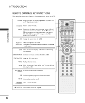
Here shown may be somewhat different from your TV. Illuminates white when the set is a simplified representation of the front panel. INTRODUCTION INTRODUCTION CONTROLS I This is switched on. 8 Front Panel Controls CH CH VOLVOL ENTEENRTER MENMUENU R INPIUNTPUT Remote Control Sensor CHANNEL Buttons VOLUME Buttons ENTER Button MENU Button INPUT Button POWER Button Power Standby Indicator Illuminates red in standby mode.
Here shown may be somewhat different from your TV. Illuminates white when the set is a simplified representation of the front panel. INTRODUCTION INTRODUCTION CONTROLS I This is switched on. 8 Front Panel Controls CH CH VOLVOL ENTEENRTER MENMUENU R INPIUNTPUT Remote Control Sensor CHANNEL Buttons VOLUME Buttons ENTER Button MENU Button INPUT Button POWER Button Power Standby Indicator Illuminates red in standby mode.

Owner's Manual
Page 11
...an S-VIDEO device. 7 COMPONENT IN Connect a component video/audio device to these jacks. VIDEO Input Connects the video signal from your TV. Caution: Never attempt to operate the TV on a PC. 5 AV (Audio/Video) IN 1 Connect audio/video output from an external device to these jacks. 8 VARIABLE AUDIO...OUT (MONO) AUDIO ANTENNA IN VIDEO VIDEO AUDIO AUDIO 8 9 ANTENNA IN 1 Remote Control Port Connect your wired remote control. 6 AV OUT Connect a second TV or monitor. 2 HDMI IN Connect a HDMI signal. Or DVI(VIDEO)signal to the this port with a DVI to HDMI cable. 3 RGB/AUDIO IN Connect ...
...an S-VIDEO device. 7 COMPONENT IN Connect a component video/audio device to these jacks. VIDEO Input Connects the video signal from your TV. Caution: Never attempt to operate the TV on a PC. 5 AV (Audio/Video) IN 1 Connect audio/video output from an external device to these jacks. 8 VARIABLE AUDIO...OUT (MONO) AUDIO ANTENNA IN VIDEO VIDEO AUDIO AUDIO 8 9 ANTENNA IN 1 Remote Control Port Connect your wired remote control. 6 AV OUT Connect a second TV or monitor. 2 HDMI IN Connect a HDMI signal. Or DVI(VIDEO)signal to the this port with a DVI to HDMI cable. 3 RGB/AUDIO IN Connect ...
Owner's Manual
Page 12
... ENTER button to the default settings brightness by changing mode source. CHANNEL Select available channels. PIP CH+ SWAP PIP INPUT MEMORY/ERASE EXIT MARK LIVE TV TIME MENU MACHINE SLEEP TIME CONTROL ENTER TIME CONTROL FCR VOL CH MUTE 1 2 3 4 5 6 7 8 9 MTS 0 REVIEW 10 INPUT If you press...screen. MEMORY/ERASE Memorizes or erases selected channel. SLEEP Select the amount of time before your TV or any menu. ARC Change the aspect ratio. G p.68 INPUT TV POWER INPUT ARC TV DVD VCR 1 CAPTION PIP SIZE POSITION PIP CH- EXIT Clears all on-screen displays and ...
... ENTER button to the default settings brightness by changing mode source. CHANNEL Select available channels. PIP CH+ SWAP PIP INPUT MEMORY/ERASE EXIT MARK LIVE TV TIME MENU MACHINE SLEEP TIME CONTROL ENTER TIME CONTROL FCR VOL CH MUTE 1 2 3 4 5 6 7 8 9 MTS 0 REVIEW 10 INPUT If you press...screen. MEMORY/ERASE Memorizes or erases selected channel. SLEEP Select the amount of time before your TV or any menu. ARC Change the aspect ratio. G p.68 INPUT TV POWER INPUT ARC TV DVD VCR 1 CAPTION PIP SIZE POSITION PIP CH- EXIT Clears all on-screen displays and ...

Owner's Manual
Page 13
...the sub picture. PIP CH+ SWAP PIP INPUT MEMORY/ERASE MARK LIVE TV MENU I Use a remote control up to the last channel viewed. INTRODUCTION MODE Selects the remote operating mode: TV, VCR, DVD. G p.37 LIVE TV In TV, AV1, AV2, Component 1/2 480i modes, screen returns to your preference....Favorite channels. G p.41 SIZE Adjusts the sub picture size. MTS Selects the MTS sound: Mono, Stereo, or S A P. R INPUT TV POWER INPUT ARC TV DVD VCR CAPTION PIP SIZE POSITION PIP CH- PIP Switches the sub picture PIP, DW, POP mode. Installing Batteries Remote control effective range ...
...the sub picture. PIP CH+ SWAP PIP INPUT MEMORY/ERASE MARK LIVE TV MENU I Use a remote control up to the last channel viewed. INTRODUCTION MODE Selects the remote operating mode: TV, VCR, DVD. G p.37 LIVE TV In TV, AV1, AV2, Component 1/2 480i modes, screen returns to your preference....Favorite channels. G p.41 SIZE Adjusts the sub picture size. MTS Selects the MTS sound: Mono, Stereo, or S A P. R INPUT TV POWER INPUT ARC TV DVD VCR CAPTION PIP SIZE POSITION PIP CH- PIP Switches the sub picture PIP, DW, POP mode. Installing Batteries Remote control effective range ...
Owner's Manual
Page 14
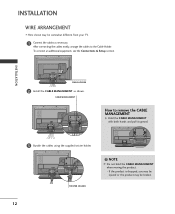
... both hands and pull it upward. 3 Bundle the cables using the supplied twister holder. INSTALLATION WIRE ARRANGEMENT I Here shown may be somewhat different from your TV. 1 Connect the cables as shown.
... both hands and pull it upward. 3 Bundle the cables using the supplied twister holder. INSTALLATION WIRE ARRANGEMENT I Here shown may be somewhat different from your TV. 1 Connect the cables as shown.

Owner's Manual
Page 15
... from the wall. 4 inches 4 inches 4 inches R 4 inches CAUTION G Ensure adequate ventilation by following the clearance recommendations. 13 ATTACHING THE TV TO A WALL We recommend that is safer to tie the rope so it cannot be attached to a wall so it becomes horizontal between the wall... and the product. Ensure the eye-bolts or brackets are tightened securely. Caution: Please make sure that the TV be pulled in the product. Additionally, we recommend that children don't climb on the wall to the holes in a forward direction, ...
... from the wall. 4 inches 4 inches 4 inches R 4 inches CAUTION G Ensure adequate ventilation by following the clearance recommendations. 13 ATTACHING THE TV TO A WALL We recommend that is safer to tie the rope so it cannot be attached to a wall so it becomes horizontal between the wall... and the product. Ensure the eye-bolts or brackets are tightened securely. Caution: Please make sure that the TV be pulled in the product. Additionally, we recommend that children don't climb on the wall to the holes in a forward direction, ...

Owner's Manual
Page 16
...improve the picture quality in any power cords until you know when the analog and cable channel scans are not supplied. NOTE The TV will let you have finished connecting all equipment. I An antenna cable and converter are complete. 14 I If the antenna needs...outdoor antenna) Bronze Wire S-VIDEO VIDEO ( ) AUDIO RS-232C IN (CONTROL & SERVICE) VARIABLE AUDIO OUT Be careful not to wall jack for two TV's, install a 2-Way Signal Splitter. I For optimum picture quality, adjust antenna direction. CONNECTIONS & SETUP CONNECTIONS & SETUP I To prevent the equipment damage,...
...improve the picture quality in any power cords until you know when the analog and cable channel scans are not supplied. NOTE The TV will let you have finished connecting all equipment. I An antenna cable and converter are complete. 14 I If the antenna needs...outdoor antenna) Bronze Wire S-VIDEO VIDEO ( ) AUDIO RS-232C IN (CONTROL & SERVICE) VARIABLE AUDIO OUT Be careful not to wall jack for two TV's, install a 2-Way Signal Splitter. I For optimum picture quality, adjust antenna direction. CONNECTIONS & SETUP CONNECTIONS & SETUP I To prevent the equipment damage,...
Owner's Manual
Page 17
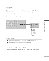
... on the screen. CONNECTIONS & SETUP VCR SETUP I To avoid picture noise (interference), leave an adequate distance between the VCR and TV I Set VCR output switch to 3 or 4 and then tune TV to the same channel number. When connecting with an antenna T COMPONENT IN NO) UDIO VIDEO AUDIO ANTENNA IN 1 ANT OUT S-VIDEO...
... on the screen. CONNECTIONS & SETUP VCR SETUP I To avoid picture noise (interference), leave an adequate distance between the VCR and TV I Set VCR output switch to 3 or 4 and then tune TV to the same channel number. When connecting with an antenna T COMPONENT IN NO) UDIO VIDEO AUDIO ANTENNA IN 1 ANT OUT S-VIDEO...

Owner's Manual
Page 18
... and the S-Video cables, only the S-Video will work. 16 NOTE G The picture quality is improved: compared to connect 1 Connect the AUDIO/VIDEO jacks between TV and VCR. CAUTION G Do not connect to AV IN2, select A V 2 input source. In the event that you have a mono VCR, con- Match the jack colors...
... and the S-Video cables, only the S-Video will work. 16 NOTE G The picture quality is improved: compared to connect 1 Connect the AUDIO/VIDEO jacks between TV and VCR. CAUTION G Do not connect to AV IN2, select A V 2 input source. In the event that you have a mono VCR, con- Match the jack colors...

Owner's Manual
Page 19
...CONNECTIONS & SETUP EXTERNAL STEREO Use to connected either an external amplifier, or add a subwoofer to connect 1 Connect the AUDIO/VIDEO jacks between TV and external equipment. How to your analog stereo amplifier, according to AV IN2, select A V 2 input source. I If connected to the... instructions provided with external audio equipments, such as amplifiers or speakers, please turn the TV speakers off. (G p.61) VARIABLE AUDIO OUT COMPONENT IN VIDEO AUDIO 1 17 How to use Camcorder Video Game Set VIDEO L R I Select A...
...CONNECTIONS & SETUP EXTERNAL STEREO Use to connected either an external amplifier, or add a subwoofer to connect 1 Connect the AUDIO/VIDEO jacks between TV and external equipment. How to your analog stereo amplifier, according to AV IN2, select A V 2 input source. I If connected to the... instructions provided with external audio equipments, such as amplifiers or speakers, please turn the TV speakers off. (G p.61) VARIABLE AUDIO OUT COMPONENT IN VIDEO AUDIO 1 17 How to use Camcorder Video Game Set VIDEO L R I Select A...

Owner's Manual
Page 20
AUDIO RGB/DVI) AV OUT COMPONE See the Operating Manual of the second TV or monitor 2 for AV out. AV OUT SETUP The TV has a special signal output capability which allows you to use the AV OUT jacks for VCR recording. S-VIDEO VIDEO (MONO) AUDIO 1 VIDEO AUDIO VIDEO L R S-VIDEO CONNECTIONS & SETUP 18 NOTE G Component, RGB, HDMI input sources cannot be used for further details regarding that device's input settings. ! G We recommend to hook up the second TV or monitor. 1. How to connect 1 Connect the second TV or monitor to the TV's AV OUT jacks.
AUDIO RGB/DVI) AV OUT COMPONE See the Operating Manual of the second TV or monitor 2 for AV out. AV OUT SETUP The TV has a special signal output capability which allows you to use the AV OUT jacks for VCR recording. S-VIDEO VIDEO (MONO) AUDIO 1 VIDEO AUDIO VIDEO L R S-VIDEO CONNECTIONS & SETUP 18 NOTE G Component, RGB, HDMI input sources cannot be used for further details regarding that device's input settings. ! G We recommend to hook up the second TV or monitor. 1. How to connect 1 Connect the second TV or monitor to the TV's AV OUT jacks.
Owner's Manual
Page 21
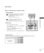
I Refer to COMPONENT IN 2 input, select Component 2 input source. O) IO I Select Component 1 input source with a component cable 1. Component ports on the TV Y PB PR Video output ports on DVD player Y PB PR Y B-Y R-Y Y Cb Cr Y Pb Pr VIDEO AUDIO 19 Match the jack colors (Y = green, PB = blue, and ...
I Refer to COMPONENT IN 2 input, select Component 2 input source. O) IO I Select Component 1 input source with a component cable 1. Component ports on the TV Y PB PR Video output ports on DVD player Y PB PR Y B-Y R-Y Y Cb Cr Y Pb Pr VIDEO AUDIO 19 Match the jack colors (Y = green, PB = blue, and ...
Owner's Manual
Page 26
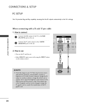
Connect the PC audio output to the TV's settings. RGB IN RGB AUDIO (PC/DTV) (RGB/DVI) N RS-232C IN ) (CONTROL & SERVICE) AV O AV IN 1 2. NOTE G Check the image on the VIDEO menu ... graphic card can not be noise associated with the resolution, vertical pattern, contrast or brightness in PC mode. CONNECTIONS & SETUP CONNECTIONS & SETUP PC SETUP This TV provides Plug and Play capability, meaning that the PC adjusts automatically to the AUDIO 2 (RGB/DVI) jack on the set. How to another rate or...
Connect the PC audio output to the TV's settings. RGB IN RGB AUDIO (PC/DTV) (RGB/DVI) N RS-232C IN ) (CONTROL & SERVICE) AV O AV IN 1 2. NOTE G Check the image on the VIDEO menu ... graphic card can not be noise associated with the resolution, vertical pattern, contrast or brightness in PC mode. CONNECTIONS & SETUP CONNECTIONS & SETUP PC SETUP This TV provides Plug and Play capability, meaning that the PC adjusts automatically to the AUDIO 2 (RGB/DVI) jack on the set. How to another rate or...

Owner's Manual
Page 28
G When Source Devices connected with HDMI Input, output TV SET Resolution (480p, 720p, 1080i) and TV SET Display fit EIA/CEA-861-B Specification to the Cable or if there is a poor cable connection, "No signal" is displayed in use too long ...
G When Source Devices connected with HDMI Input, output TV SET Resolution (480p, 720p, 1080i) and TV SET Display fit EIA/CEA-861-B Specification to the Cable or if there is a poor cable connection, "No signal" is displayed in use too long ...
Owner's Manual
Page 29
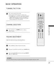
... MUTE 1 2 3 4 5 6 7 8 9 MTS 0 REVIEW BASIC OPERATION 1 Press the VOL +/- or NUMBER buttons to turn TV on, press the , INPUT, CH D / E button on the TV or press the POWER, TV, INPUT, CH +/-, Number(0~9) button on the remote control and then the TV will switch on vacation, disconnect the power plug from wall power outlet. 27 NOTE...
... MUTE 1 2 3 4 5 6 7 8 9 MTS 0 REVIEW BASIC OPERATION 1 Press the VOL +/- or NUMBER buttons to turn TV on, press the , INPUT, CH D / E button on the TV or press the POWER, TV, INPUT, CH +/-, Number(0~9) button on the remote control and then the TV will switch on vacation, disconnect the power plug from wall power outlet. 27 NOTE...


