Owners Manual
Page 5
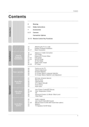
... Setup Digital Audio Output PC Setup 29 29 29 29 30 31 31 32 33 33 34 35 35_36 37 38 39 40 41 41 _42 43 43 Turning on the TV Volume Adjustment Channel Selection On Screen Menus Language Selection On Screen Menus Selection and Adjustment EZ Scan (Channel Search...) Manual Scan Channel Edit DTV Signal Strength Input Source Input Label Auto Picture Control(EZ Picture) Color Temperature Control XD Advanced-Cinema 3:2 Mode /...
... Setup Digital Audio Output PC Setup 29 29 29 29 30 31 31 32 33 33 34 35 35_36 37 38 39 40 41 41 _42 43 43 Turning on the TV Volume Adjustment Channel Selection On Screen Menus Language Selection On Screen Menus Selection and Adjustment EZ Scan (Channel Search...) Manual Scan Channel Edit DTV Signal Strength Input Source Input Label Auto Picture Control(EZ Picture) Color Temperature Control XD Advanced-Cinema 3:2 Mode /...

Owners Manual
Page 8
Illuminates white when the set is switched on . This is switched on . 60P01 D = CHANNEL (A, V') Buttons - VOLUME (_,_) Buttons ENTER Button MENU Button INPUT Button (b/t (Power) Button I Remote Control Sensor Power Standby Indicator Illuminates red in standby mode. ,, illuminates green when the set is a simplified representation of front panel. - This picture shown below may be somewhat different from your TV. 42PC3D/3DV, 50PC3D Remote Control Sensor Power/Standby Indicator ,, illuminates red in standby mode. Introduction Controls (Model Name: 42PC3D/3DV, 50PC3D, 60PC1D) -
Illuminates white when the set is switched on . This is switched on . 60P01 D = CHANNEL (A, V') Buttons - VOLUME (_,_) Buttons ENTER Button MENU Button INPUT Button (b/t (Power) Button I Remote Control Sensor Power Standby Indicator Illuminates red in standby mode. ,, illuminates green when the set is a simplified representation of front panel. - This picture shown below may be somewhat different from your TV. 42PC3D/3DV, 50PC3D Remote Control Sensor Power/Standby Indicator ,, illuminates red in standby mode. Introduction Controls (Model Name: 42PC3D/3DV, 50PC3D, 60PC1D) -
Owners Manual
Page 9
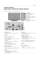
...CONTROL & SERVICE) PORT Connect to the 1 (DVI) port with AC power. Caution: Never attempt to operate the TV on a PC. @ Power Cord Socket For operation with a DVI to 1 (DVI) or 2. This picture shown below may be somewhat different from various types of equipment. device to @AV OUT Connect a second... TV or monitor. @AV (Audio/Video) IN 1 Connect audio/video device to these ports do not work. @ ...
...CONTROL & SERVICE) PORT Connect to the 1 (DVI) port with AC power. Caution: Never attempt to operate the TV on a PC. @ Power Cord Socket For operation with a DVI to 1 (DVI) or 2. This picture shown below may be somewhat different from various types of equipment. device to @AV OUT Connect a second... TV or monitor. @AV (Audio/Video) IN 1 Connect audio/video device to these ports do not work. @ ...

Owners Manual
Page 10
ENTER Button Button -- Buttons (A, _) (_,_) Buttons -- INPUT Button -- (b/l (Power) Button Swivel Stand (42:LC2D Only) - This picture shown below may be conveniently swivelled on . The TV can be somewhat different from your TV. This is switched on its stand 30 ° to the left or right to provide the optimum viewing angle. 10 Remote Control Sensor Power/Standby Indicator ,, illuminates red in standby mode. ,, illuminates green when the set is a simplified representation of front panel. - Introduction Controls (Model Name: 32/37/42LC2D, 32LC2DU) -
ENTER Button Button -- Buttons (A, _) (_,_) Buttons -- INPUT Button -- (b/l (Power) Button Swivel Stand (42:LC2D Only) - This picture shown below may be conveniently swivelled on . The TV can be somewhat different from your TV. This is switched on its stand 30 ° to the left or right to provide the optimum viewing angle. 10 Remote Control Sensor Power/Standby Indicator ,, illuminates red in standby mode. ,, illuminates green when the set is a simplified representation of front panel. - Introduction Controls (Model Name: 32/37/42LC2D, 32LC2DU) -
Owners Manual
Page 11
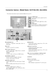
... @COMPONENT IN Connect a component these ports do not work. @ HDMI IN Connect a HDMI signal to operate the TV on a PC. video/audio @AV OUT Connect a second TV or monitor. AUDIO IN (RGB/DVl) Connect the monitor output appropriate input port. Connect cable signals to the O Remote...power. from a video device. Introduction Connecti on Opt"lon s (Model Name: 32/37/42LC2D, 32LC2DU) - O Power Cord Socket For operation with a DVI to the RS-232C port on DC power. 11 S-VIDEO Input Provides better picture quality than the video input. Or DVI (VIDEO)signal to these jacks.
... @COMPONENT IN Connect a component these ports do not work. @ HDMI IN Connect a HDMI signal to operate the TV on a PC. video/audio @AV OUT Connect a second TV or monitor. AUDIO IN (RGB/DVl) Connect the monitor output appropriate input port. Connect cable signals to the O Remote...power. from a video device. Introduction Connecti on Opt"lon s (Model Name: 32/37/42LC2D, 32LC2DU) - O Power Cord Socket For operation with a DVI to the RS-232C port on DC power. 11 S-VIDEO Input Provides better picture quality than the video input. Or DVI (VIDEO)signal to these jacks.

Owners Manual
Page 13
Introduction TV INPUT _ INPUT EZ PIC EZSOUND SAP CCC) CCC) CCC) 1 CC m, ADJUST i VCBiOVOJBVNBSUJC'O",N.cS,,.,o' control some video cassette recorders or DVD players ( RECORD button is net available for the progra m s character. Increases/decreases the sound level. Returns to enter a program number f0r mu!tipie program chan- J Selects a factory preset picture mode depending...
Introduction TV INPUT _ INPUT EZ PIC EZSOUND SAP CCC) CCC) CCC) 1 CC m, ADJUST i VCBiOVOJBVNBSUJC'O",N.cS,,.,o' control some video cassette recorders or DVD players ( RECORD button is net available for the progra m s character. Increases/decreases the sound level. Returns to enter a program number f0r mu!tipie program chan- J Selects a factory preset picture mode depending...
Owners Manual
Page 14
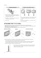
...sturdy rope (not provided as shown in the picture. * If your product has the bolts in a forward direction, tially causing injury or damaging the product. It is mounted on the wall. Don't mix old or used batteries in the product. up the TV close to tie the rope so it cannot ... ! Additionally, we recommend that you set up to tie the product. poten- 42PC3D/3DV, 50PC3D 60PC1D 32/37/42LC2D, 32LC2DU _ Insert the eye-bolts (or TV brackets and bolts) to tighten the product to the wall as parts of the product, must purchase separately) to 7 meters distance and within the...
...sturdy rope (not provided as shown in the picture. * If your product has the bolts in a forward direction, tially causing injury or damaging the product. It is mounted on the wall. Don't mix old or used batteries in the product. up the TV close to tie the rope so it cannot ... ! Additionally, we recommend that you set up to tie the product. poten- 42PC3D/3DV, 50PC3D 60PC1D 32/37/42LC2D, 32LC2DU _ Insert the eye-bolts (or TV brackets and bolts) to tighten the product to the wall as parts of the product, must purchase separately) to 7 meters distance and within the...

Owners Manual
Page 15
I n St a ! [a t i1o n Installation DESKTOPPEDESTALINSTALLATION For proper ventilation, allow a clearance of 4inches on each side from your TV. This picture shown below may be somewhat different from the wall. 42PC3D/3DV, 50PC3D, 60P01D 32/37/42LC2D, 32LC2DU iiii_i!i!iiiii_iiiiiiiiiiiiiiiiiiiiiiiiiiiiiiiiiiiiii_i_i_i_i_iii_i_i!_iiiii!ii_i_;i;1i!!!_i_!_ii!ii_!_iiIi!_i_iiiiIi_i_iiiii[iiii[ii _; Do not tr-y to ground the...
I n St a ! [a t i1o n Installation DESKTOPPEDESTALINSTALLATION For proper ventilation, allow a clearance of 4inches on each side from your TV. This picture shown below may be somewhat different from the wall. 42PC3D/3DV, 50PC3D, 60P01D 32/37/42LC2D, 32LC2DU iiii_i!i!iiiii_iiiiiiiiiiiiiiiiiiiiiiiiiiiiiiiiiiiiii_i_i_i_i_iii_i_i!_iiiii!ii_i_;i;1i!!!_i_!_ii!ii_!_iiIi!_i_iiiiIi_i_iiiii[iiii[ii _; Do not tr-y to ground the...

Owners Manual
Page 18
..., adjust antenna direction if needed. Bronze Wire Be careful not to wall jack for assistance. 18 Cable TV Wall Jack Turn €lockwise to improve picture quality, purchase and install a signal amplifier. if the antenna is not installed properly, contact your dealer for outdoor antenna. o... s NOTE: All cables shown are not included with the TV - if the antenna needs to be split for two TV's, install a "2-Way ...
..., adjust antenna direction if needed. Bronze Wire Be careful not to wall jack for assistance. 18 Cable TV Wall Jack Turn €lockwise to improve picture quality, purchase and install a signal amplifier. if the antenna is not installed properly, contact your dealer for outdoor antenna. o... s NOTE: All cables shown are not included with the TV - if the antenna needs to be split for two TV's, install a "2-Way ...
Owners Manual
Page 19
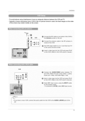
... is used; To avoid picture noise (interference), leave an adequate distance between TV and VCR. "e VCR @ Connect the RF antenna out socket of the VCR to the Antenna s0cket on the set 19 Match the jack colors (Video = ... VCR. (Refer t0 the vcR owner's manual,) VCR AUD tit 0 OUTPUT Connect the AUDIO/VIDEO jacks between the VCR and TV. - Typically a frozen still picture from the VCR to 3 or 4 and then tune TV @ Insert a video tape into the VCR and press PLAY on the remote control. - connect me audio cable from a VCR...
... is used; To avoid picture noise (interference), leave an adequate distance between TV and VCR. "e VCR @ Connect the RF antenna out socket of the VCR to the Antenna s0cket on the set 19 Match the jack colors (Video = ... VCR. (Refer t0 the vcR owner's manual,) VCR AUD tit 0 OUTPUT Connect the AUDIO/VIDEO jacks between the VCR and TV. - Typically a frozen still picture from the VCR to 3 or 4 and then tune TV @ Insert a video tape into the VCR and press PLAY on the remote control. - connect me audio cable from a VCR...
Owners Manual
Page 20
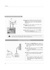
... the remote control. _ !f connected to AV IN2, se!ect AV2 input s0urce. [ Do not c0nnect to external equipment operating guide. ,This TV finds the connected input sources automatically for AV1. If connected to AV IN1 input, select AVl input source. RGB. Operate the corresponding external equipment....= red (SVeidleecot A=Vy2elloinwp.ut AsuoduiorceLewftith= wushiinteg, thaendiNAPuUdiTo button on the set. Video Game Set 2O @ Connect the AUDIO/VIDEO jacks between TV and external equipment. The picture quality is @ Select AV! Installation VIDE0 inPut on the remote control. -
... the remote control. _ !f connected to AV IN2, se!ect AV2 input s0urce. [ Do not c0nnect to external equipment operating guide. ,This TV finds the connected input sources automatically for AV1. If connected to AV IN1 input, select AVl input source. RGB. Operate the corresponding external equipment....= red (SVeidleecot A=Vy2elloinwp.ut AsuoduiorceLewftith= wushiinteg, thaendiNAPuUdiTo button on the set. Video Game Set 2O @ Connect the AUDIO/VIDEO jacks between TV and external equipment. The picture quality is @ Select AV! Installation VIDE0 inPut on the remote control. -
Owners Manual
Page 21
TV can recewe the video and audio signal simultaneously with using a HDMI cable If the DVD supports Auto HDMI function, the DVD output resolution will be automatically set to 1280x720p. 21 To get the best picture quality, adjust the output resolution of the DVD to AV IN2, select AV 2 input source. Installation O Select...
TV can recewe the video and audio signal simultaneously with using a HDMI cable If the DVD supports Auto HDMI function, the DVD output resolution will be automatically set to 1280x720p. 21 To get the best picture quality, adjust the output resolution of the DVD to AV IN2, select AV 2 input source. Installation O Select...
Owners Manual
Page 22
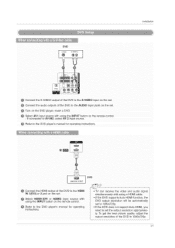
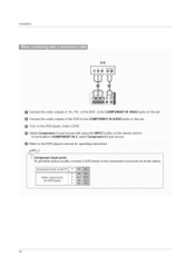
Connect the audio outputs of the DVD to COMPONENT IN 2. select Component 2 input source. Component Input porte To get better picture quality, connect a DVD player to the DVD player's manual for operating instructions. - Turn on the remote control. - Select Component 1 input source with using the INPUT ... to the COMPONENT IN AUDIO jacks on the set . If connected to the COMPONENT IN VIDEO jacks on DVD player 22 Component ports on the TV Video output ports on the set . Installation DVD @ Connect the video outputs (Y. PB.
Connect the audio outputs of the DVD to COMPONENT IN 2. select Component 2 input source. Component Input porte To get better picture quality, connect a DVD player to the DVD player's manual for operating instructions. - Turn on the remote control. - Select Component 1 input source with using the INPUT ... to the COMPONENT IN AUDIO jacks on the set . If connected to the COMPONENT IN VIDEO jacks on DVD player 22 Component ports on the TV Video output ports on the set . Installation DVD @ Connect the video outputs (Y. PB.
Owners Manual
Page 23
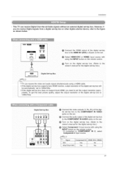
O Select HDMI1iDVI or HDMI2 input source with using the INPUT button on the remote control Turn on the set -top box.) TV can receive Digital Over-the-air/Cable signals without an external digital set -top box to the owner's manual for the digital set . If the ... 1(DVl) or 2 jack on the digital set-top box. (Refer to 1280x720p. 23 To get the best picture quality, adjust the output resolution of the digital set the output resolution appropriately. Installation - This TV can receive the video and audio signal simultaneously using a HDMI cable. If the digital set-top box supports...
O Select HDMI1iDVI or HDMI2 input source with using the INPUT button on the remote control Turn on the set -top box.) TV can receive Digital Over-the-air/Cable signals without an external digital set -top box to the owner's manual for the digital set . If the ... 1(DVl) or 2 jack on the digital set-top box. (Refer to 1280x720p. 23 To get the best picture quality, adjust the output resolution of the digital set the output resolution appropriately. Installation - This TV can receive the video and audio signal simultaneously using a HDMI cable. If the digital set-top box supports...
Owners Manual
Page 24
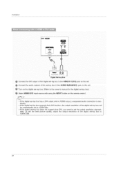
... Box @ Connect the DVl output of the digital set-top box to the HDMI IN I(DVI) jack on the remote control. To get the best picture quality, adjust the output resolution of the digital set-top box will be automatically set to 1280x720p. • If the digital set-top box does...
... Box @ Connect the DVl output of the digital set-top box to the HDMI IN I(DVI) jack on the remote control. To get the best picture quality, adjust the output resolution of the digital set-top box will be automatically set to 1280x720p. • If the digital set-top box does...
Owners Manual
Page 26
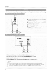
...) jack on the set the output resolution appropriately. To get the best picture quality, adjust the output resolution of the PC to 1024x768. 60Hz. 26 Installation - This TV provides Plug and Play capability, meaning that the PC adjusts automatically to the TV's settings. ,_ ® i [ (PC) jack on the set . _ Connect the PC audo...
...) jack on the set the output resolution appropriately. To get the best picture quality, adjust the output resolution of the PC to 1024x768. 60Hz. 26 Installation - This TV provides Plug and Play capability, meaning that the PC adjusts automatically to the TV's settings. ,_ ® i [ (PC) jack on the set . _ Connect the PC audo...
Owners Manual
Page 27
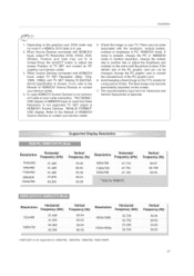
... Input, output PC Resolution (VGA, SVGA, XGA, WXGA), Position and Size may become permanently imprinted on the menu until the picture is not supported TV SET output in HDMI/DVl Input. If noise is present, change the PC or HDMI/DVI mode to adjust the screen Position ... not connect- oa ., 0 o.0 Ho.zonta Vort ca S i i_!_!_!i!iill Frequency (kHz) Frequency (Hz) Frequency (kHz)Frequency (Hz) "720x400 800X600 1024x768 31.4.69 37.879 48.363 70.08 60.31 60.00 1366x768 47.130 59.65 Resoi Utie n Horizontal Frequency (kHz) Vertical Frequency (Hz) _,_,, 2:31469 /Zox4_u 1280x720...
... Input, output PC Resolution (VGA, SVGA, XGA, WXGA), Position and Size may become permanently imprinted on the menu until the picture is not supported TV SET output in HDMI/DVl Input. If noise is present, change the PC or HDMI/DVI mode to adjust the screen Position ... not connect- oa ., 0 o.0 Ho.zonta Vort ca S i i_!_!_!i!iill Frequency (kHz) Frequency (Hz) Frequency (kHz)Frequency (Hz) "720x400 800X600 1024x768 31.4.69 37.879 48.363 70.08 60.31 60.00 1366x768 47.130 59.65 Resoi Utie n Horizontal Frequency (kHz) Vertical Frequency (Hz) _,_,, 2:31469 /Zox4_u 1280x720...

Owners Manual
Page 28
.... H buttons to * When you change the resolution, select the proper resolution in present input to see the beet picture appearance, " initializing (Reset to original factory values) I \ Position This function is to adjust picture to PC input and select the RGB-PC. POSITION.SIZE.or PHASE. 2 Press ENTER button and then use _1...
.... H buttons to * When you change the resolution, select the proper resolution in present input to see the beet picture appearance, " initializing (Reset to original factory values) I \ Position This function is to adjust picture to PC input and select the RGB-PC. POSITION.SIZE.or PHASE. 2 Press ENTER button and then use _1...

Owners Manual
Page 32
There are displayed in front of that channel number. 5 Press EXiT button to return to TV viewing or press MENU button to return to select the gETUP menu. A Custom List can add or delete the channel to/from the Custom List ... ENTER button. Both of the screen. The channels in the Custom List are available after _Z Scan on or off with channel numbers and a preview picture. 4 Use A / T / _l/1_ button to select a channel and then use the ENTER button to add or delete scanned channels. You can add or delete the...
There are displayed in front of that channel number. 5 Press EXiT button to return to TV viewing or press MENU button to return to select the gETUP menu. A Custom List can add or delete the channel to/from the Custom List ... ENTER button. Both of the screen. The channels in the Custom List are available after _Z Scan on or off with channel numbers and a preview picture. 4 Use A / T / _l/1_ button to select a channel and then use the ENTER button to add or delete scanned channels. You can add or delete the...

Owners Manual
Page 33
... so you can watch your TV, cable TV, VCR, DVD, or any other devices that are to experience picture degradatien. - Shows how strong your antenna or digital cable input. Setup Menu Options continued Operation - DTV Signals. Only when the input signal is DTV or ... select DTV Signal. 3 View the on-screen signal strength monitor to see the quality of the signal being received. 4 Press EXIT button to return to TV viewing or press MENU button to return to the previous menu. 33 The higher the signal strength, the less likely you need to select Input...
... so you can watch your TV, cable TV, VCR, DVD, or any other devices that are to experience picture degradatien. - Shows how strong your antenna or digital cable input. Setup Menu Options continued Operation - DTV Signals. Only when the input signal is DTV or ... select DTV Signal. 3 View the on-screen signal strength monitor to see the quality of the signal being received. 4 Press EXIT button to return to TV viewing or press MENU button to return to the previous menu. 33 The higher the signal strength, the less likely you need to select Input...


