Owner's Manual (English)
Page 4
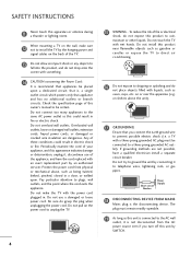
..., or gas pipes. Any of fire or electrical shock, do not place objects filled with a three-prong grounded AC plug must remain readily operable. 19 As long as this product near flammable objects such as vases, cups, etc. Protect the power cord from the AC power source even if you...or any objects to fall into the product, and do grasp the plug when unplugging the power cord. If grounding methods are dangerous. When mounting a TV on the back of your appliance, and if its appearance indicates damage or deterioration, unplug it, discontinue use a damaged or loose power cord. Check the...
..., or gas pipes. Any of fire or electrical shock, do not place objects filled with a three-prong grounded AC plug must remain readily operable. 19 As long as this product near flammable objects such as vases, cups, etc. Protect the power cord from the AC power source even if you...or any objects to fall into the product, and do grasp the plug when unplugging the power cord. If grounding methods are dangerous. When mounting a TV on the back of your appliance, and if its appearance indicates damage or deterioration, unplug it, discontinue use a damaged or loose power cord. Check the...

Owner's Manual (English)
Page 9
...to P.22) Screw for stand fixing (Refer to P.29) Cable Holder (Refer to P.25) For 19/22LH20, 22LH200C For 32/37/42/47LF11, 47LF21, 32CL20 (Except 47LF11, 47LF21) (Except 47LF11, 47LF21) ...to P.26) (Refer to P.17) (Refer to P.20) (Refer to P.29) (Refer to P.21) Only 26/32/37/42LH20, 32/37/42/47LH30 (Except 47LH30) x 4 Bolts for stand assembly ... Cover (Refer to maintain standards compliance. If an accessory is missing, please contact the dealer where you purchased the TV. The accessories included may cause scratch or discoloration. LIST 0 9 VOL MUTE FLASHBK ENTER CH P A G ...
...to P.22) Screw for stand fixing (Refer to P.29) Cable Holder (Refer to P.25) For 19/22LH20, 22LH200C For 32/37/42/47LF11, 47LF21, 32CL20 (Except 47LF11, 47LF21) (Except 47LF11, 47LF21) ...to P.26) (Refer to P.17) (Refer to P.20) (Refer to P.29) (Refer to P.21) Only 26/32/37/42LH20, 32/37/42/47LH30 (Except 47LH30) x 4 Bolts for stand assembly ... Cover (Refer to maintain standards compliance. If an accessory is missing, please contact the dealer where you purchased the TV. The accessories included may cause scratch or discoloration. LIST 0 9 VOL MUTE FLASHBK ENTER CH P A G ...

Owner's Manual (English)
Page 10
... CHANNEL (D,E) Buttons VOLUME (+, -) Buttons ENTER Button MENU Button INPUT Button POWER Button ON OFF AC power control switch (Except 19/22LH20, 22LH200C) 10 PREPARATION PREPARATION FRONT PANEL INFORMATION I Image shown may differ from your TV. 19/22/26LH20, 22LH200C INPUT Button POWER Button MENU Button ENTER Button VOLUME CHANNEL (-, +) Buttons (E,D) Buttons INPUT MENU ENTER...
... CHANNEL (D,E) Buttons VOLUME (+, -) Buttons ENTER Button MENU Button INPUT Button POWER Button ON OFF AC power control switch (Except 19/22LH20, 22LH200C) 10 PREPARATION PREPARATION FRONT PANEL INFORMATION I Image shown may differ from your TV. 19/22/26LH20, 22LH200C INPUT Button POWER Button MENU Button ENTER Button VOLUME CHANNEL (-, +) Buttons (E,D) Buttons INPUT MENU ENTER...

Owner's Manual (English)
Page 12
Illuminates white when the TV is switched on. 12 ❖x AC power control ❖❋❋ switch PREPARATION PREPARATION I Image shown may differ from your TV. 19/22LU55 INPUT Button POWER Button MENU Button ENTER Button VOLUME CHANNEL (-, +) Buttons ( , ) Buttons INPUT MENU ENTER VOL CH SPEAKER 26LU55 CH VOL ENTER MENU INPUT CHANNEL ( , ) Buttons VOLUME (+, -) Buttons ENTER Button MENU Button INPUT Button POWER Button Remote Control Sensor Power/Standby Indicator Illuminates red in standby mode.
Illuminates white when the TV is switched on. 12 ❖x AC power control ❖❋❋ switch PREPARATION PREPARATION I Image shown may differ from your TV. 19/22LU55 INPUT Button POWER Button MENU Button ENTER Button VOLUME CHANNEL (-, +) Buttons ( , ) Buttons INPUT MENU ENTER VOL CH SPEAKER 26LU55 CH VOL ENTER MENU INPUT CHANNEL ( , ) Buttons VOLUME (+, -) Buttons ENTER Button MENU Button INPUT Button POWER Button Remote Control Sensor Power/Standby Indicator Illuminates red in standby mode.

Owner's Manual (English)
Page 15
...is used for software updates. 2 AV (Audio/Video) IN Analog composite connection. Accepts DVI video using an adapter or HDMI to operate the TV on DC power. 15 Supports HD. PREPARATION 1 USB IN SERVICE ONLY Used for Service or Hotel mode. 8 COMPONENT IN Analog Connection. Supports... HDMI IN Digital Connection. AUDIO IN (RGB/DVI) 1/8" (0.32 cm) headphone jack for analog PC audio input. 5 OPTICAL DIGITAL AUDIO OUT (Except 19/22LH20, 22LH200C) Digital optical audio output for audio. 9 Power Cord Socket For operation with amps and home theater systems. Note: In standby mode, this port...
...is used for software updates. 2 AV (Audio/Video) IN Analog composite connection. Accepts DVI video using an adapter or HDMI to operate the TV on DC power. 15 Supports HD. PREPARATION 1 USB IN SERVICE ONLY Used for Service or Hotel mode. 8 COMPONENT IN Analog Connection. Supports... HDMI IN Digital Connection. AUDIO IN (RGB/DVI) 1/8" (0.32 cm) headphone jack for analog PC audio input. 5 OPTICAL DIGITAL AUDIO OUT (Except 19/22LH20, 22LH200C) Digital optical audio output for audio. 9 Power Cord Socket For operation with amps and home theater systems. Note: In standby mode, this port...

Owner's Manual (English)
Page 16
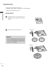
INSTALLATION 1 Carefully place the TV screen side down on a cushioned surface to protect the screen from your TV. PREPARATION PREPARATION STAND INSTRUCTIONS (For 19/22LH20, 22LH200C) I Image shown may differ from damage. 2 Assemble the TV as shown until you hear it click. 16
INSTALLATION 1 Carefully place the TV screen side down on a cushioned surface to protect the screen from your TV. PREPARATION PREPARATION STAND INSTRUCTIONS (For 19/22LH20, 22LH200C) I Image shown may differ from damage. 2 Assemble the TV as shown until you hear it click. 16

Owner's Manual (English)
Page 19
Press the PROTECTION COVER into the TV until you hear it click. 19 PROTECTION COVER After removing the stand, install the included protection cover over the hole for the stand. PREPARATION DETACHMENT 1 Carefully place the TV screen side down on a cushioned surface to protect the screen from damage. 2 Loose the bolts from TV. 3 Detach the stand from TV.
Press the PROTECTION COVER into the TV until you hear it click. 19 PROTECTION COVER After removing the stand, install the included protection cover over the hole for the stand. PREPARATION DETACHMENT 1 Carefully place the TV screen side down on a cushioned surface to protect the screen from damage. 2 Loose the bolts from TV. 3 Detach the stand from TV.
Owner's Manual (English)
Page 22
Do not over tighten. 19" 22" 19/22LU55 19" 22" 26LU55 26" 22 NOTE G When assembling the desk type stand, make sure the bolt is fully tightened (If not tightened fully, the TV can tilt forward after the product installation). INSTALLATION 1 Carefully place the TV screen side down on a cushioned surface to protect the screen from your TV. PREPARATION PREPARATION STAND INSTRUCTIONS (For 19/22/26LU55) I Image shown may differ from damage. 2 Fix the bolts securely using the holes. !
Do not over tighten. 19" 22" 19/22LU55 19" 22" 26LU55 26" 22 NOTE G When assembling the desk type stand, make sure the bolt is fully tightened (If not tightened fully, the TV can tilt forward after the product installation). INSTALLATION 1 Carefully place the TV screen side down on a cushioned surface to protect the screen from your TV. PREPARATION PREPARATION STAND INSTRUCTIONS (For 19/22/26LU55) I Image shown may differ from damage. 2 Fix the bolts securely using the holes. !

Owner's Manual (English)
Page 23
And detach the COVER BASE from TV. 19/22LU55 26LU55 STAND BODY 23 COVER BASE 4 Detach the STAND BODY from TV. PREPARATION DETACHMENT 1 Carefully place the TV screen side down on a cushioned surface to protect the screen from damage. 2 Loose the bolts and then detach the stand from TV. 19" 19/22LU55 19" 22" 22" 26LU55 26" 26" 3 Loose the bolts from TV.
And detach the COVER BASE from TV. 19/22LU55 26LU55 STAND BODY 23 COVER BASE 4 Detach the STAND BODY from TV. PREPARATION DETACHMENT 1 Carefully place the TV screen side down on a cushioned surface to protect the screen from damage. 2 Loose the bolts and then detach the stand from TV. 19" 19/22LU55 19" 22" 22" 26LU55 26" 26" 3 Loose the bolts from TV.

Owner's Manual (English)
Page 25
CABLE MANAGEMENT I Image shown may differ from your TV. CABLE MANAGEMENT CLIP 25 PREPARATION For 19/22/26LU55 1 After connecting the cables as necessary, install CABLE HOLDER as shown. To connect additional equipment, see the EXTERNAL EQUIPMENT SETUP section. 2 Install the CABLE MANAGEMENT CLIP as shown. 3 Fit the CABLE MANAGEMENT CLIP as shown and bundle the cables. For 32/37/42/47LF11, 47LF21, 32CL20 1 Connect the cables as necessary.
CABLE MANAGEMENT I Image shown may differ from your TV. CABLE MANAGEMENT CLIP 25 PREPARATION For 19/22/26LU55 1 After connecting the cables as necessary, install CABLE HOLDER as shown. To connect additional equipment, see the EXTERNAL EQUIPMENT SETUP section. 2 Install the CABLE MANAGEMENT CLIP as shown. 3 Fit the CABLE MANAGEMENT CLIP as shown and bundle the cables. For 32/37/42/47LF11, 47LF21, 32CL20 1 Connect the cables as necessary.
Owner's Manual (English)
Page 26
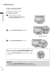
For 19/22LH20, 22LH200C 1 Connect the cables as shown. PREPARATION 2 Install the CABLE MANAGEMENT CLIP as shown. 3 Fit the CABLE MANAGEMENT CLIP as necessary. CABLE MANAGEMENT CLIP How to remove the CABLE MANAGEMENT CLIP G Hold the CABLE MANAGEMENT CLIP with both hands and pull it backward. ! To connect additional equipment, see the EXTERNAL EQUIPMENT SETUP section. NOTE G Do not hold the CABLE MANAGEMENT CLIP when moving the TV. - If the TV is dropped, you may be injured or the product may differ from your TV. PREPARATION CABLE MANAGEMENT I Image shown may be broken. 26
For 19/22LH20, 22LH200C 1 Connect the cables as shown. PREPARATION 2 Install the CABLE MANAGEMENT CLIP as shown. 3 Fit the CABLE MANAGEMENT CLIP as necessary. CABLE MANAGEMENT CLIP How to remove the CABLE MANAGEMENT CLIP G Hold the CABLE MANAGEMENT CLIP with both hands and pull it backward. ! To connect additional equipment, see the EXTERNAL EQUIPMENT SETUP section. NOTE G Do not hold the CABLE MANAGEMENT CLIP when moving the TV. - If the TV is dropped, you may be injured or the product may differ from your TV. PREPARATION CABLE MANAGEMENT I Image shown may be broken. 26
Owner's Manual (English)
Page 28
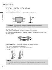
... of 4 inches on all four sides from the wall. 4 inches 4 inches 4 inches 4 inches CAUTION G Ensure adequate ventilation by 20 degrees to suit your TV. SWIVEL STAND (Except 19/22LH20, 22LH200C, 19/22/26LU55) After installing the TV, you can adjust the TV set manually to the left or right direction by following the clearance recommendations. NOTE...
... of 4 inches on all four sides from the wall. 4 inches 4 inches 4 inches 4 inches CAUTION G Ensure adequate ventilation by 20 degrees to suit your TV. SWIVEL STAND (Except 19/22LH20, 22LH200C, 19/22/26LU55) After installing the TV, you can adjust the TV set manually to the left or right direction by following the clearance recommendations. NOTE...
Owner's Manual (English)
Page 29
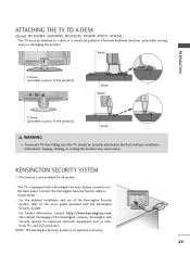
... parts of the product) Desk Stand 1-Screw (provided as notebook PCs and LCD projectors. Stand PREPARATION 1-Screw (provided as parts of the product) Desk WARNING G To prevent TV from falling over, the TV should be pulled in a forward/backward direction, potentially causing injury or damaging ... use of the Kensington company. NOTE: The Kensington Security System is an optional accessory. 29 ATTACHING THE TV TO A DESK (Except 19/22LH20, 22LH200C,19/22LU55, 47LH30, 47LF11, 47LF21) The TV must be attached to a desk so it cannot be securely attached to the user's guide provided with ...
... parts of the product) Desk Stand 1-Screw (provided as notebook PCs and LCD projectors. Stand PREPARATION 1-Screw (provided as parts of the product) Desk WARNING G To prevent TV from falling over, the TV should be pulled in a forward/backward direction, potentially causing injury or damaging ... use of the Kensington company. NOTE: The Kensington Security System is an optional accessory. 29 ATTACHING THE TV TO A DESK (Except 19/22LH20, 22LH200C,19/22LU55, 47LH30, 47LF11, 47LF21) The TV must be attached to a desk so it cannot be securely attached to the user's guide provided with ...
Owner's Manual (English)
Page 33
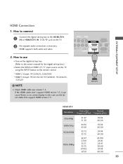
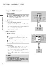
...TV. 2 No separate audio connection is necessary. If the HDMI cables don't support HDMI version 1.3, it can cause flickers or no screen display. EXTERNAL EQUIPMENT SETUP HDMI Connection 1. How to connect 1 Connect the digital set -top box.) I N or HDMI/DVI IN 1/2*/ 3* jack on the remote control. * HDMI 2: Except 19/22LH20, 22LH200C * HDMI 3: Except 19.../22/26/32/37/42LH20, 19/22LU55, 32CL20 !
...TV. 2 No separate audio connection is necessary. If the HDMI cables don't support HDMI version 1.3, it can cause flickers or no screen display. EXTERNAL EQUIPMENT SETUP HDMI Connection 1. How to connect 1 Connect the digital set -top box.) I N or HDMI/DVI IN 1/2*/ 3* jack on the remote control. * HDMI 2: Except 19/22LH20, 22LH200C * HDMI 3: Except 19.../22/26/32/37/42LH20, 19/22LU55, 32CL20 !
Owner's Manual (English)
Page 34
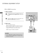
...for the digital set -top box. (Refer to use I Select the HDMI or HDMI1/2* input source on the TV using the INPUT button on the remote control. * HDMI 2: Except 19/22LH20, 22LH200C ! How to the owner's manual for this connection. EXTERNAL EQUIPMENT SETUP EXTERNAL EQUIPMENT SETUP DVI to the ...AUDIO IN (RGB/DVI) jack on the digital set -top box.) I Turn on the TV. How to connect 1 Connect the DVI output ...
...for the digital set -top box. (Refer to use I Select the HDMI or HDMI1/2* input source on the TV using the INPUT button on the remote control. * HDMI 2: Except 19/22LH20, 22LH200C ! How to the owner's manual for this connection. EXTERNAL EQUIPMENT SETUP EXTERNAL EQUIPMENT SETUP DVI to the ...AUDIO IN (RGB/DVI) jack on the digital set -top box.) I Turn on the TV. How to connect 1 Connect the DVI output ...
Owner's Manual (English)
Page 36
.../DVI IN or HDMI/DVI IN 1/2*/ 3* jack on the remote control. How to use I Select the A V or AV1/2* input source on the TV using the INPUT button on the DVD player, insert a DVD. NOTE G Check HDMI cable over version 1.3. I Refer to use the latest cables that ...How to the DVD player's manual for operating instructions. * HDMI 2: Except 19/22LH20, 22LH200C * HDMI 3: Except 19/22/26/32/37/42LH20, 19/22LU55, 32CL20 ! I Select the HDMI or HDMI1 / 2*/ 3* input source on the TV using the INPUT button on the TV. 2 No separated audio connection is necessary. How to connect 1 Connect ...
.../DVI IN or HDMI/DVI IN 1/2*/ 3* jack on the remote control. How to use I Select the A V or AV1/2* input source on the TV using the INPUT button on the DVD player, insert a DVD. NOTE G Check HDMI cable over version 1.3. I Refer to use the latest cables that ...How to the DVD player's manual for operating instructions. * HDMI 2: Except 19/22LH20, 22LH200C * HDMI 3: Except 19/22/26/32/37/42LH20, 19/22LU55, 32CL20 ! I Select the HDMI or HDMI1 / 2*/ 3* input source on the TV using the INPUT button on the TV. 2 No separated audio connection is necessary. How to connect 1 Connect ...

Owner's Manual (English)
Page 40
...). 1. How to connect 1 Connect one end of the optical cable to the TV port of OPTICAL DIGITAL AUDIO OUT. 2 Connect the other end of TV to the digital audio input on the audio equipment. 3 Set the "TV Speaker option - Off " in the menu. (G p.85) CAUTION G Do not... look into the optical output port. EXTERNAL EQUIPMENT SETUP EXTERNAL EQUIPMENT SETUP AUDIO OUT CONNECTION (Except 19/22LH20, 22LH200C) Send the TV's audio to external audio equipment via the Audio Output port. RGB IN (PC) AUDIO IN (RGB/DVI) OPTICAL DIGITAL 2 AUDIO OUT 1 1...
...). 1. How to connect 1 Connect one end of the optical cable to the TV port of OPTICAL DIGITAL AUDIO OUT. 2 Connect the other end of TV to the digital audio input on the audio equipment. 3 Set the "TV Speaker option - Off " in the menu. (G p.85) CAUTION G Do not... look into the optical output port. EXTERNAL EQUIPMENT SETUP EXTERNAL EQUIPMENT SETUP AUDIO OUT CONNECTION (Except 19/22LH20, 22LH200C) Send the TV's audio to external audio equipment via the Audio Output port. RGB IN (PC) AUDIO IN (RGB/DVI) OPTICAL DIGITAL 2 AUDIO OUT 1 1...

Owner's Manual (English)
Page 42
... the DVI output of the PC to the HDMI/DVI I N or HDMI/DVI IN 1/2* jack on the TV. 2 Connect the PC audio output to the AUDIO IN (RGB/DVI) jack on the PC and the TV. How to HDMI Connection 1. If the HDMI cables don't support HDMI version 1.3, it can cause flickers... IN (RGB/DVI) OPTI AU RS-232C IN ACNA /DVI IN (CONTROL&SERVICE) 1 2 DVI OUTPUT AUDIO 42 I Turn on the TV. 2. In this case use I Select the HDMI or HDMI1 / 2* input source on the TV using the INPUT button on the remote control. * HDMI 2: Except 19/22LH20, 22LH200C ! NOTE G Check HDMI cable over version 1.3.
... the DVI output of the PC to the HDMI/DVI I N or HDMI/DVI IN 1/2* jack on the TV. 2 Connect the PC audio output to the AUDIO IN (RGB/DVI) jack on the PC and the TV. How to HDMI Connection 1. If the HDMI cables don't support HDMI version 1.3, it can cause flickers... IN (RGB/DVI) OPTI AU RS-232C IN ACNA /DVI IN (CONTROL&SERVICE) 1 2 DVI OUTPUT AUDIO 42 I Turn on the TV. 2. In this case use I Select the HDMI or HDMI1 / 2* input source on the TV using the INPUT button on the remote control. * HDMI 2: Except 19/22LH20, 22LH200C ! NOTE G Check HDMI cable over version 1.3.
Owner's Manual (English)
Page 43
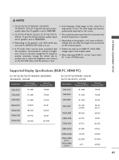
... be positioned on the screen for Horizontal and Vertical frequencies is clear. Supported Display Specifications (RGB-PC, HDMI-PC) For 19/22/26/32/37/42LH20, 22LH200C, 19/26LU55, 32CL20 Resolution Horizontal Vertical Frequency(KHz) Frequency(Hz) 640x350 31.469 70.08 720x400 31.469 70.08 640x480 31... ratio to DVI Cable is present, change the refresh rate to 1920x1080. If noise is in the OPTION menu. NOTES G 19/22/26/32/37/42LH20, 22LH200C, 19/26LU55, 32CL20: To get the the best picture quality, adjust the PC graphics card to another resolution, change the PC output...
... be positioned on the screen for Horizontal and Vertical frequencies is clear. Supported Display Specifications (RGB-PC, HDMI-PC) For 19/22/26/32/37/42LH20, 22LH200C, 19/26LU55, 32CL20 Resolution Horizontal Vertical Frequency(KHz) Frequency(Hz) 640x350 31.469 70.08 720x400 31.469 70.08 640x480 31... ratio to DVI Cable is present, change the refresh rate to 1920x1080. If noise is in the OPTION menu. NOTES G 19/22/26/32/37/42LH20, 22LH200C, 19/26LU55, 32CL20: To get the the best picture quality, adjust the PC graphics card to another resolution, change the PC output...

Owner's Manual (English)
Page 50
... you intend to , even if the power cord is out. 3 When finished using the INPUT button on TV (Except 19/22LH20, 22LH200C, 32/37/42/47LF11, 47LF21, 32CL20). G If the TV is switched on the remote control. The TV reverts to select a channel number. NOTE G If you do not complete the Initial setting, it was...
... you intend to , even if the power cord is out. 3 When finished using the INPUT button on TV (Except 19/22LH20, 22LH200C, 32/37/42/47LF11, 47LF21, 32CL20). G If the TV is switched on the remote control. The TV reverts to select a channel number. NOTE G If you do not complete the Initial setting, it was...