FS-1028MFP/1128MFP Operation Guide Rev-3
Page 22
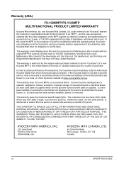
... CONSEQUENTIAL DAMAGES WHICH MAY ARISE OUT OF THE USE OF, OR INABILITY TO USE, THE MFP. Replacement Maintenance Kits have had the serial number modified, altered, or removed. Warranty (USA) FS-1028MFP/FS-1128MFP MULTIFUNCTIONAL PRODUCT LIMITED WARRANTY Kyocera Mita America, Inc. In the event the MFP or an accessory is authorized to extend the time...
... CONSEQUENTIAL DAMAGES WHICH MAY ARISE OUT OF THE USE OF, OR INABILITY TO USE, THE MFP. Replacement Maintenance Kits have had the serial number modified, altered, or removed. Warranty (USA) FS-1028MFP/FS-1128MFP MULTIFUNCTIONAL PRODUCT LIMITED WARRANTY Kyocera Mita America, Inc. In the event the MFP or an accessory is authorized to extend the time...
FS-1028MFP/1128MFP Operation Guide Rev-3
Page 347
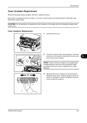
..., be sure to clean the parts as shown in the figure in the plastic bag (supplied with the new toner kit) and discard it later according to the unlock position. OPERATION GUIDE 9-5 Maintenance Toner Container Replacement When the message display displays Add toner, replace the toner. Dirty parts may cause burns. Push... the front cover. 2 Turn the lock lever to the local code or regulations for waste disposal. 3 Take the new toner container out of the toner kit.
..., be sure to clean the parts as shown in the figure in the plastic bag (supplied with the new toner kit) and discard it later according to the unlock position. OPERATION GUIDE 9-5 Maintenance Toner Container Replacement When the message display displays Add toner, replace the toner. Dirty parts may cause burns. Push... the front cover. 2 Turn the lock lever to the local code or regulations for waste disposal. 3 Take the new toner container out of the toner kit.

Service Manual
Page 36
...errors are logged. Indicates the log counter of replacement. T: Toner container Example: 00: Black All instances including C6000: 4 M: Maintenance kit those are not occurred 00: MK-130/MK-132 are logged. Completion Press the stop key. Items Description (4) Service Call Log...occurrence of the previous replacement of toner container is displayed. 1-3-8 Count. Item Code of maintenance replacing item (1 byte, 2 categories) First byte (Replacing item) 01: Toner container 02: Maintenance kit Second byte (Type of the self diagnostics error. T00: 1 The toner container has ...
...errors are logged. Indicates the log counter of replacement. T: Toner container Example: 00: Black All instances including C6000: 4 M: Maintenance kit those are not occurred 00: MK-130/MK-132 are logged. Completion Press the stop key. Items Description (4) Service Call Log...occurrence of the previous replacement of toner container is displayed. 1-3-8 Count. Item Code of maintenance replacing item (1 byte, 2 categories) First byte (Replacing item) 01: Toner container 02: Maintenance kit Second byte (Type of the self diagnostics error. T00: 1 The toner container has ...

Service Manual
Page 58
... No. Description U100 Setting the main high voltage Description Controls the main charger high voltage to clear the drum drive time during maintenance service (replacing the maintenance kit). (See page 2-4-4, page 1-5-29 and page 1-5-30) Method 1. Purpose To change the setting when any density problems, such as a reference when correcting the high voltage... drive time for the primary transfer. The count is used as too dark or light, occur. Completion Press the stop key. The screen for selecting a maintenance item No.
... No. Description U100 Setting the main high voltage Description Controls the main charger high voltage to clear the drum drive time during maintenance service (replacing the maintenance kit). (See page 2-4-4, page 1-5-29 and page 1-5-30) Method 1. Purpose To change the setting when any density problems, such as a reference when correcting the high voltage... drive time for the primary transfer. The count is used as too dark or light, occur. Completion Press the stop key. The screen for selecting a maintenance item No.

Service Manual
Page 59
...on. Press the start key. 2. The setting is displayed. 1-3-31 Setting range 1 (ON) / 0 (OFF) 0 to operate during maintenance service (replacing the maintenance kit). (See page 2-4-4, page 1-5-29 and page 1-5-30) Method 1. Select [INST MODE] using the cursor up /down keys and press the ...start key. Press the start key. Toner installation is complete. 2JN-2 Maintenance item No. Purpose To operate when a faulty image (black ...
...on. Press the start key. 2. The setting is displayed. 1-3-31 Setting range 1 (ON) / 0 (OFF) 0 to operate during maintenance service (replacing the maintenance kit). (See page 2-4-4, page 1-5-29 and page 1-5-30) Method 1. Select [INST MODE] using the cursor up /down keys and press the ...start key. Press the start key. Toner installation is complete. 2JN-2 Maintenance item No. Purpose To operate when a faulty image (black ...

Service Manual
Page 64
... keys. 3. Change the setting using the cursor up /down keys. 2. Description Setting range Initial setting Maintenance cycle 0 to clear the count during maintenance service (replacing the maintenance kit). (See page 2-4-4, page 1-5-29 and page 1-5-30) Method 1. Press the start key. Description U244.... 2. The screen for that sensor will be highlighted. When a sensor is displayed. Purpose To check the maintenance count. Press the start key. The maintenance count is detected to check the status. Press the start key. Select [CLEAR] using the cursor up /down...
... keys. 3. Change the setting using the cursor up /down keys. 2. Description Setting range Initial setting Maintenance cycle 0 to clear the count during maintenance service (replacing the maintenance kit). (See page 2-4-4, page 1-5-29 and page 1-5-30) Method 1. Press the start key. Description U244.... 2. The screen for that sensor will be highlighted. When a sensor is displayed. Purpose To check the maintenance count. Press the start key. The maintenance count is detected to check the status. Press the start key. Select [CLEAR] using the cursor up /down...

Service Manual
Page 77
...Method 1. U605 Clearing data Description Initializes data related to adjust the number of the machine as transmission history. The screen for selecting a maintenance item No. 2JN Maintenance item No. Description Setting range Initial setting Number of fax/telephone rings 0 to 15 2 (120 V)/1 (220-240 V) If you ... Press the start key. 2. Description U603 Setting user data 1 Description Makes user settings to enable the use of the facsimile kit if necessary. Press the start key. Select [LINE TYPE]. Select the setting using the cursor left/right keys or numeric keys...
...Method 1. U605 Clearing data Description Initializes data related to adjust the number of the machine as transmission history. The screen for selecting a maintenance item No. 2JN Maintenance item No. Description Setting range Initial setting Number of fax/telephone rings 0 to 15 2 (120 V)/1 (220-240 V) If you ... Press the start key. 2. Description U603 Setting user data 1 Description Makes user settings to enable the use of the facsimile kit if necessary. Press the start key. Select [LINE TYPE]. Select the setting using the cursor left/right keys or numeric keys...

Service Manual
Page 91
... network. 1. OFF Does not detect the dial tone. Setting the connection to PBX/PSTN Selects if a fax is set when installing the facsimile kit. Initial setting: ON 2. 2JN Maintenance item No. Purpose To be set using the cursor up /down keys. DIAL TONE Sets PSTN dial tone detection. Initial setting: PSTN 2. Initial...
... network. 1. OFF Does not detect the dial tone. Setting the connection to PBX/PSTN Selects if a fax is set when installing the facsimile kit. Initial setting: ON 2. 2JN Maintenance item No. Purpose To be set using the cursor up /down keys. DIAL TONE Sets PSTN dial tone detection. Initial setting: PSTN 2. Initial...

Service Manual
Page 181
Check or replace the developing unit and refit all the removed parts. U130 Initial setting for the developing unit (see page 1-3-36) 2. U251 Clearing the maintenance count (see page 1-3-31) 2JN-2 Developing unit Front cover Figure 1-5-44 1-5-29 U111 Clearing the drum drive time (see page 2-4-4), perform following maintenance modes. 1. NOTE: When the periodic maintenance (replacing the maintenance kit, see page 1-3-30) 3. Open the front cover. 2. Remove the developing unit. 3. 1-5-5 Developing section (1) Detaching and refitting the developing unit Procedure 1.
Check or replace the developing unit and refit all the removed parts. U130 Initial setting for the developing unit (see page 1-3-36) 2. U251 Clearing the maintenance count (see page 1-3-31) 2JN-2 Developing unit Front cover Figure 1-5-44 1-5-29 U111 Clearing the drum drive time (see page 2-4-4), perform following maintenance modes. 1. NOTE: When the periodic maintenance (replacing the maintenance kit, see page 1-3-30) 3. Open the front cover. 2. Remove the developing unit. 3. 1-5-5 Developing section (1) Detaching and refitting the developing unit Procedure 1.

Service Manual
Page 182
Remove the developing unit (See page 1-529). 2. NOTE: When the periodic maintenance (replacing the maintenance kit, see page 1-3-30) 3. U111 Clearing the drum drive time (see page 2-4-4), perform following maintenance modes. 1. Check or replace the drum unit and refit all the removed parts. U251 Clearing the maintenance count (see page 1-3-31) Drum unit Figure 1-5-45 1-5-30 U130 Initial setting for the developing unit (see page 1-3-36) 2. 2JN-2 1-5-6 Drum section (1) Detaching and refitting the drum unit Procedure 1. Remove the drum unit. 3.
Remove the developing unit (See page 1-529). 2. NOTE: When the periodic maintenance (replacing the maintenance kit, see page 1-3-30) 3. U111 Clearing the drum drive time (see page 2-4-4), perform following maintenance modes. 1. Check or replace the drum unit and refit all the removed parts. U251 Clearing the maintenance count (see page 1-3-31) Drum unit Figure 1-5-45 1-5-30 U130 Initial setting for the developing unit (see page 1-3-36) 2. 2JN-2 1-5-6 Drum section (1) Detaching and refitting the drum unit Procedure 1. Remove the drum unit. 3.


