
FS-1100/1300D Operation Guide Rev-1.2 (Basic)
Page 23
.... pressed. Torn pieces of personal injury. Note Do not remove the toner container from the carton until you ship the printer, remove and pack the develper unit and drum unit in a plastic bag and ship them separately from the printer. CAUTION When pulling the paper, pull it gently so as...To start printing, click OK. software. Convention Italic Typeface Bold Braket Bold Description Example Used to emphasize a key word, Refer to remove and may be easily overlooked, deterring the paper jam recovery. Used to tear it in This Guide This manual uses the following conventions...
.... pressed. Torn pieces of personal injury. Note Do not remove the toner container from the carton until you ship the printer, remove and pack the develper unit and drum unit in a plastic bag and ship them separately from the printer. CAUTION When pulling the paper, pull it gently so as...To start printing, click OK. software. Convention Italic Typeface Bold Braket Bold Description Example Used to emphasize a key word, Refer to remove and may be easily overlooked, deterring the paper jam recovery. Used to tear it in This Guide This manual uses the following conventions...
FS-1100/1300D Operation Guide Rev-1.2 (Basic)
Page 70
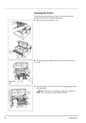
Cleaning the Printer To avoid print quality problems, the interior of the printer. Note The drum unit is sensitive to light for more than five minutes. 4-6 Maintenance Never expose the drum unit to light. Developer Unit Drum Unit 3 Remove the drum unit from the printer by holding the green levers with the toner container out of the printer must be cleaned with every toner container replacement. 1 Open the top cover and front cover. 2 Lift the develper unit together with both hands.
Cleaning the Printer To avoid print quality problems, the interior of the printer. Note The drum unit is sensitive to light for more than five minutes. 4-6 Maintenance Never expose the drum unit to light. Developer Unit Drum Unit 3 Remove the drum unit from the printer by holding the green levers with the toner container out of the printer must be cleaned with every toner container replacement. 1 Open the top cover and front cover. 2 Lift the develper unit together with both hands.

FS-1100/1300D Operation Guide Rev-1.2 (Basic)
Page 71
... the charger cleaner to its original position (CLEANER HOME POSITION ). Maintenance 4-7 IMPORTANT Remove the fixing tape on a clean, level surface. IMPORTANT Take care not to touch the transfer roller (black) during cleaning. 6 On the drum unit, slide the charger cleaner (green) back and forth 2 or 3 times ...charger wire, then return it to its home position. 7 When cleaning is complete, return the drum unit to clean dust and dirt away from the metal registration roller. 4 Place the drum unit flat on the charger cleaner before cleaning for the first time. IMPORTANT Do not place the...
... the charger cleaner to its original position (CLEANER HOME POSITION ). Maintenance 4-7 IMPORTANT Remove the fixing tape on a clean, level surface. IMPORTANT Take care not to touch the transfer roller (black) during cleaning. 6 On the drum unit, slide the charger cleaner (green) back and forth 2 or 3 times ...charger wire, then return it to its home position. 7 When cleaning is complete, return the drum unit to clean dust and dirt away from the metal registration roller. 4 Place the drum unit flat on the charger cleaner before cleaning for the first time. IMPORTANT Do not place the...
FS-1100/1300D Operation Guide Rev-1.2 (Basic)
Page 73
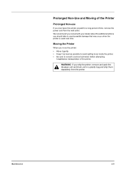
... with your dealer about the additional actions you should take to consult a service technician before attempting longdistance transportation of time, remove the power cord from the printer. WARNING If you ship the printer, remove and pack the develper unit and drum unit in a plastic bag and ship them separately from the wall outlet. Moving the...
... with your dealer about the additional actions you should take to consult a service technician before attempting longdistance transportation of time, remove the power cord from the printer. WARNING If you ship the printer, remove and pack the develper unit and drum unit in a plastic bag and ship them separately from the wall outlet. Moving the...
FS-1100/1300D Operation Guide Rev-1.2 (Basic)
Page 87
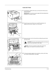
...to be pinched by holding the green levers with the toner container out of the printer. 3 Remove the drum unit from the printer by rollers, pull it may result in burn injury. CAUTION The fuser unit inside the printer is sensitive to step 2. 2 Open the top cover and front cover, and lift...hands. Do not touch it, as it along the normal running direction of the printer. Note The drum is hot. Troubleshooting 5-13 Inside the Printer 1 Pull the paper cassette all the way out of the paper. Remove any partially fed paper. Proceed to light. Never expose the develper unit to light...
...to be pinched by holding the green levers with the toner container out of the printer. 3 Remove the drum unit from the printer by rollers, pull it may result in burn injury. CAUTION The fuser unit inside the printer is sensitive to step 2. 2 Open the top cover and front cover, and lift...hands. Do not touch it, as it along the normal running direction of the printer. Note The drum is hot. Troubleshooting 5-13 Inside the Printer 1 Pull the paper cassette all the way out of the paper. Remove any partially fed paper. Proceed to light. Never expose the develper unit to light...

Service Manual
Page 9
... toner bottles in a furnace, etc...• Should smoke be seen coming from the copier, remove the power plug from the wall outlet immediately...3.Miscellaneous WARNING • Never attempt to heat the drum or expose it with care by following the instructions below Use only a small amount of solvent... at a time, being careful not to evaporate completely before refitting the covers or turning the power switch on. Wipe spills off completely. • Do not remove the ozone filter...
... toner bottles in a furnace, etc...• Should smoke be seen coming from the copier, remove the power plug from the wall outlet immediately...3.Miscellaneous WARNING • Never attempt to heat the drum or expose it with care by following the instructions below Use only a small amount of solvent... at a time, being careful not to evaporate completely before refitting the covers or turning the power switch on. Wipe spills off completely. • Do not remove the ozone filter...
Service Manual
Page 11
...Overall ...1-1-3 (2) Operation panel...1-1-4 1-1-3 Machine cross section ...1-1-5 1-2 Installation 1-2-1 Installation environment ...1-2-1 1-2-2 Unpacking ...1-2-2 (1) Removing the tapes ...1-2-3 1-2-3 Installing the expanded memory (option 1-2-4 1-2-4 Installing the memory card (optional)...1-2-5 1-2-5 Installing ... Assembly and Disassembly 1-5-1 Precautions for assembly and disassembly 1-5-1 (1) Precautions ...1-5-1 (2) Drum...1-5-1 (3) Toner container ...1-5-1 (4) How to tell a genuine Kyocera Mita toner container 1-5-2 1-5-2 Outer covers ...1-5-3 (1) Detaching and refitting the top cover...
...Overall ...1-1-3 (2) Operation panel...1-1-4 1-1-3 Machine cross section ...1-1-5 1-2 Installation 1-2-1 Installation environment ...1-2-1 1-2-2 Unpacking ...1-2-2 (1) Removing the tapes ...1-2-3 1-2-3 Installing the expanded memory (option 1-2-4 1-2-4 Installing the memory card (optional)...1-2-5 1-2-5 Installing ... Assembly and Disassembly 1-5-1 Precautions for assembly and disassembly 1-5-1 (1) Precautions ...1-5-1 (2) Drum...1-5-1 (3) Toner container ...1-5-1 (4) How to tell a genuine Kyocera Mita toner container 1-5-2 1-5-2 Outer covers ...1-5-3 (1) Detaching and refitting the top cover...
Service Manual
Page 47
...or 1-5-12). (5) Black horizontal streaks. Defective drum unit. Defective paper specifications. Paper with the one that the drum shaft and the grounding tab (printer) are in good contact. Replace paper with rugged surface or dump tends to remove oil and debris. Defective fuser unit (heat roller... procedures/corrective measures If the defects occur at regular intervals of 62.8 mm/2 1/2" (See page 2-4-3), the problem may be the damaged drum (in the drum unit). Apply the grounding tab a small amount of 73.162 mm/2 7/8", or 78.5 mm/3 1/16" (See page 2-4-3), the ...
...or 1-5-12). (5) Black horizontal streaks. Defective drum unit. Defective paper specifications. Paper with the one that the drum shaft and the grounding tab (printer) are in good contact. Replace paper with rugged surface or dump tends to remove oil and debris. Defective fuser unit (heat roller... procedures/corrective measures If the defects occur at regular intervals of 62.8 mm/2 1/2" (See page 2-4-3), the problem may be the damaged drum (in the drum unit). Apply the grounding tab a small amount of 73.162 mm/2 7/8", or 78.5 mm/3 1/16" (See page 2-4-3), the ...

Service Manual
Page 48
...the developing unit with the one (See page 1-5-11). 1-4-12 Defective drum unit. Defective main charger grid. Check procedures/corrective measures Remove the drum unit (See page 1-5-12). Refer to the operation guide. For ...details, refer to conserve toner for check, replace the current developing unit in the drum unit) is known to its original position (CLEANER HOME POSITION). Check procedures/corrective measures Replace paper with a new one that the cleaning blade (in the printer...
...the developing unit with the one (See page 1-5-11). 1-4-12 Defective drum unit. Defective main charger grid. Check procedures/corrective measures Remove the drum unit (See page 1-5-12). Refer to the operation guide. For ...details, refer to conserve toner for check, replace the current developing unit in the drum unit) is known to its original position (CLEANER HOME POSITION). Check procedures/corrective measures Replace paper with a new one that the cleaning blade (in the printer...

Service Manual
Page 49
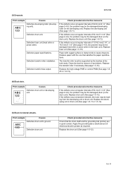
... polygon motor (laser scanner unit). Print example Causes ABC 123 Toner contamination in various parts. If the transfer roller is contaminated with toner, clean the transfer roller using a vacuum cleaner or by toner accumulated on the top edge or back of the drum and developing unit... measures Dirty edges and back of the paper can be straight. Check procedures/corrective measures Replace the laser scanner unit (See page 1-5-30). Clean these areas and parts to remove toner. 2H5/2HS (9) Dirt on such parts as the paper chute guide, paper conveying paths, the...
... polygon motor (laser scanner unit). Print example Causes ABC 123 Toner contamination in various parts. If the transfer roller is contaminated with toner, clean the transfer roller using a vacuum cleaner or by toner accumulated on the top edge or back of the drum and developing unit... measures Dirty edges and back of the paper can be straight. Check procedures/corrective measures Replace the laser scanner unit (See page 1-5-30). Clean these areas and parts to remove toner. 2H5/2HS (9) Dirt on such parts as the paper chute guide, paper conveying paths, the...

Service Manual
Page 53
... and at a relative humidity not higher than 90% RH. When removing the hook of the drum. Take care not to turn the power switch off and disconnect the power plug before starting disassembly. Do not touch the drum surface with oil, clean it be sure to strong direct light.... Should it . (3) Toner container Store the toner container(s) in temperature and humidity. When removing the drum unit, never expose the drum surface to release the hook. Avoid abrupt changes in...
... and at a relative humidity not higher than 90% RH. When removing the hook of the drum. Take care not to turn the power switch off and disconnect the power plug before starting disassembly. Do not touch the drum surface with oil, clean it be sure to strong direct light.... Should it . (3) Toner container Store the toner container(s) in temperature and humidity. When removing the drum unit, never expose the drum surface to release the hook. Avoid abrupt changes in...

Service Manual
Page 64
Check or replace the drum unit and refit all the removed parts. Remove the drum unit. 3. Remove the developing unit (See page 1-511). 2. Drum unit Figure 1-5-16 1-5-12 2H5/2HS 1-5-5 Drum section (1) Detaching and refitting the drum unit Procedure 1.
Check or replace the drum unit and refit all the removed parts. Remove the drum unit. 3. Remove the developing unit (See page 1-511). 2. Drum unit Figure 1-5-16 1-5-12 2H5/2HS 1-5-5 Drum section (1) Detaching and refitting the drum unit Procedure 1.

Service Manual
Page 65
Remove the drum unit (See page 1-5-12). 2. While pushing on the main plate (ᕃ), slide the main charger unit (ᕄ). Remove the main charger unit by lifting it. 5. Remove the tape. 3. Figure 1-5-17 Main charger unit Figure 1-5-18 1-5-13 Tape 2H5/2HS-1 Main charger unit Drum unit Main charger unit Main plate ᕃ ᕄ 4. Check or replace the main charger unit and refit all the removed parts. (2) Detaching and refitting the main charger unit Procedure 1.
Remove the drum unit (See page 1-5-12). 2. While pushing on the main plate (ᕃ), slide the main charger unit (ᕄ). Remove the main charger unit by lifting it. 5. Remove the tape. 3. Figure 1-5-17 Main charger unit Figure 1-5-18 1-5-13 Tape 2H5/2HS-1 Main charger unit Drum unit Main charger unit Main plate ᕃ ᕄ 4. Check or replace the main charger unit and refit all the removed parts. (2) Detaching and refitting the main charger unit Procedure 1.

Service Manual
Page 66
Remove the paper chute guide. Paper chute guide Paper chute guide Hook Hook Hook Hook Figure 1-5-19 1-5-14 Remove the drum unit (See page 1-5-12). 3. Slide the paper chute guide and unhook the hooks. 4. Remove the developing unit (See page 1-511). 2. 2H5/2HS 1-5-6 Transfer/separation section (1) Detaching and refitting the transfer roller Procedure 1.
Remove the paper chute guide. Paper chute guide Paper chute guide Hook Hook Hook Hook Figure 1-5-19 1-5-14 Remove the drum unit (See page 1-5-12). 3. Slide the paper chute guide and unhook the hooks. 4. Remove the developing unit (See page 1-511). 2. 2H5/2HS 1-5-6 Transfer/separation section (1) Detaching and refitting the transfer roller Procedure 1.

Service Manual
Page 77
... Figure 1-5-35 1-5-25 (4) Detaching and refitting the high voltage PWB Procedure 1. Remove the developing unit (See page 1-511). 2. Turn the printer with the bottom side up. 7. Remove the drum unit (See page 1-5-12). 3. Remove the DU holder. 2H5/2HS Stop ring DU holder 10. Pull out the DU... bush. 11. Remove the DU cover assembly. Remove the power source PWB (See page 1-5-22). ...
... Figure 1-5-35 1-5-25 (4) Detaching and refitting the high voltage PWB Procedure 1. Remove the developing unit (See page 1-511). 2. Turn the printer with the bottom side up. 7. Remove the drum unit (See page 1-5-12). 3. Remove the DU holder. 2H5/2HS Stop ring DU holder 10. Pull out the DU... bush. 11. Remove the DU cover assembly. Remove the power source PWB (See page 1-5-22). ...

Service Manual
Page 95
... development, the electrostatic image is constituted over the aluminum cylinder base. If the drum (drum unit) remains removed form the printer, it is susceptible to damage caused by resin, it should be stored in a cool, dark place. . 3 4 2 1 Figure 2-1-9 Drum section (1) Drum (2) Drum shaft (3) Drum cover A (4) Drum cover B 2-1-5 Substances like water, alcohol, organic solvent, etc., should be strictly avoided. As...
... development, the electrostatic image is constituted over the aluminum cylinder base. If the drum (drum unit) remains removed form the printer, it is susceptible to damage caused by resin, it should be stored in a cool, dark place. . 3 4 2 1 Figure 2-1-9 Drum section (1) Drum (2) Drum shaft (3) Drum cover A (4) Drum cover B 2-1-5 Substances like water, alcohol, organic solvent, etc., should be strictly avoided. As...


