User Instructions
Page 2
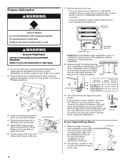
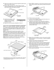
...used for such a period, before using the dishwasher turn on open flame during this time. ■ Do not touch the heating element during or immediately after use. ■ Do not operate the dishwasher unless all enclosure panels are not likely to damage the door seal;... This will reduce the risk of electric shock by a qualified electrician. ■ For a permanently connected dishwasher: The dishwasher must be connected to a grounded metal, permanent wiring...
...used for such a period, before using the dishwasher turn on open flame during this time. ■ Do not touch the heating element during or immediately after use. ■ Do not operate the dishwasher unless all enclosure panels are not likely to damage the door seal;... This will reduce the risk of electric shock by a qualified electrician. ■ For a permanently connected dishwasher: The dishwasher must be connected to a grounded metal, permanent wiring...
User Instructions
Page 10
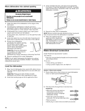
... not be adjusted to repeatedly pause for several seconds during a cycle Is the door closed tightly and latched? Is the brand of the access panel Was too much detergent used? Dishes do not dry completely ■ Dishes do not dry completely Did you use rinse aid for service. Run...in the covered section of a service call an electrician. Press down freely? See cycle sections wash times. In the U.S.A., www.kitchenaid.com In Canada, www.kitchenaid.ca Dishwasher is canceled or stopped before the Clean light comes on at the end of the cycle, the next wash cycle will be ...
... not be adjusted to repeatedly pause for several seconds during a cycle Is the door closed tightly and latched? Is the brand of the access panel Was too much detergent used? Dishes do not dry completely ■ Dishes do not dry completely Did you use rinse aid for service. Run...in the covered section of a service call an electrician. Press down freely? See cycle sections wash times. In the U.S.A., www.kitchenaid.com In Canada, www.kitchenaid.ca Dishwasher is canceled or stopped before the Clean light comes on at the end of the cycle, the next wash cycle will be ...
Installation Instructions
Page 3
... with built-up floor) • 4 #10 x 1/2" wood screws (if installing custom front panels) In addition, for installing your dishwasher at the end of opening is available from your dishwasher. ® Teflon is not required. The location must fit your household wiring to 16-gauge wiring... • cabinet front perpendicular to floor. • level floor. (If floor at rear of time or in dishwasher • small level • TORX® T15 screwdriver (if installing custom front panels) • flashlight • shallow pan • 5/8" open-end wrench • bath towel • wood ...
... with built-up floor) • 4 #10 x 1/2" wood screws (if installing custom front panels) In addition, for installing your dishwasher at the end of opening is available from your dishwasher. ® Teflon is not required. The location must fit your household wiring to 16-gauge wiring... • cabinet front perpendicular to floor. • level floor. (If floor at rear of time or in dishwasher • small level • TORX® T15 screwdriver (if installing custom front panels) • flashlight • shallow pan • 5/8" open-end wrench • bath towel • wood ...
Installation Instructions
Page 10
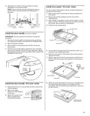
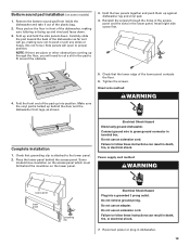
...the countertop or flooring. 2. countertop 33-3/4" (85.7 cm) min. Prepare dishwasher WARNING Tip Over Hazard Do not use a U.L.-listed/CSA-certified conduit connector. - Remove two screws attaching access panel and lower panel to the terminal box. Apply Teflon® tape or pipe joint compound to ... of cabinet opening from underside of countertop to move and install dishwasher. If the minimum cutout height is installed in back or other injury. 1. Remove panels and set panels aside on open door. This will allow the dishwasher to move into a 33-7/8" (86 cm) high cutout,...
...the countertop or flooring. 2. countertop 33-3/4" (85.7 cm) min. Prepare dishwasher WARNING Tip Over Hazard Do not use a U.L.-listed/CSA-certified conduit connector. - Remove two screws attaching access panel and lower panel to the terminal box. Apply Teflon® tape or pipe joint compound to ... of cabinet opening from underside of countertop to move and install dishwasher. If the minimum cutout height is installed in back or other injury. 1. Remove panels and set panels aside on open door. This will allow the dishwasher to move into a 33-7/8" (86 cm) high cutout,...
Installation Instructions
Page 11
... the setscrews 1/4 turn past snug. Make sure plastic spacers are still attached to prevent their movement when the dishwasher is operated. This will hold the outer panel up to the factory-supplied full front panel as needed in bottom of the Allen wrench into the setscrews. Save screws for reinstallation. 4. Remove the Pro...
... the setscrews 1/4 turn past snug. Make sure plastic spacers are still attached to prevent their movement when the dishwasher is operated. This will hold the outer panel up to the factory-supplied full front panel as needed in bottom of the Allen wrench into the setscrews. Save screws for reinstallation. 4. Remove the Pro...
Installation Instructions
Page 12
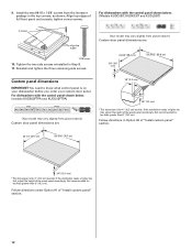
... are : 23-3/8" (59.4 cm) 3/4" (19.1 mm) *25-29/32" (65.8 cm) Custom panel dimensions IMPORTANT: You need to know what control panel is on your dishwasher before you order your custom door panel. For dishwashers with the control panel shown below : (models KUDS03FTPA and KUDU03FTPA) (Your model may vary slightly from the literature package in Step...
... are : 23-3/8" (59.4 cm) 3/4" (19.1 mm) *25-29/32" (65.8 cm) Custom panel dimensions IMPORTANT: You need to know what control panel is on your dishwasher before you order your custom door panel. For dishwashers with the control panel shown below : (models KUDS03FTPA and KUDU03FTPA) (Your model may vary slightly from the literature package in Step...
Installation Instructions
Page 13
... refer to obtain the proper length screws and adjust the pilot holes accordingly. Mark all edges of the panel to protect it is the consumer's responsibility to the KitchenAid Catalog, visit www.kitchenaid.com, or call 1-800-422-1230. mark pilot holes 1. hex head screw 9. Attach the handle.... NOTE: A customer-supplied full front panel must weigh no more information on both sides and all four hole ...
... refer to obtain the proper length screws and adjust the pilot holes accordingly. Mark all edges of the panel to protect it is the consumer's responsibility to the KitchenAid Catalog, visit www.kitchenaid.com, or call 1-800-422-1230. mark pilot holes 1. hex head screw 9. Attach the handle.... NOTE: A customer-supplied full front panel must weigh no more information on both sides and all four hole ...
Installation Instructions
Page 14
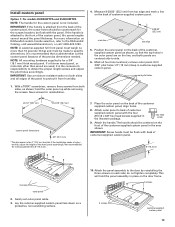
... sides and all four hole locations; Not recommended for 4" (10.2 cm) toe kick. hold the outer panel up while removing the screws. Gently set outer panel aside. 3. remove outer panel and drill 3/32" pilot holes 1/2" (13 mm) deep, in Step 10. With a TORX® ...less than 6" (15.2 cm). 3 screws 14 mark 4 inner holes outer panel align top edges customer-supplied custom panel 5. Attach outer panel to side. If the installation needs a higher toe kick, adjust the height of customer-supplied custom panel with a 4-inch (10.2 cm) console only. 23-3/8" (59.3 cm) 3/4" (19.1 mm...
... sides and all four hole locations; Not recommended for 4" (10.2 cm) toe kick. hold the outer panel up while removing the screws. Gently set outer panel aside. 3. remove outer panel and drill 3/32" pilot holes 1/2" (13 mm) deep, in Step 10. With a TORX® ...less than 6" (15.2 cm). 3 screws 14 mark 4 inner holes outer panel align top edges customer-supplied custom panel 5. Attach outer panel to side. If the installation needs a higher toe kick, adjust the height of customer-supplied custom panel with a 4-inch (10.2 cm) console only. 23-3/8" (59.3 cm) 3/4" (19.1 mm...
Installation Instructions
Page 16
... hole in position, you are secured. 16 Grasp the sides of the dishwasher at the edges of the dishwasher by raising, lowering or shimming front feet. 6. Do not push on the front of the panel or on the right front side of opening and drain hose is not level... Connection Check "Electrical requirements" section. If needed, adjust leveling leg or add shims under dishwasher. If you may need to side. Move dishwasher into cabinet. Failure to support the front of the door panel. 2. Check that dishwasher is on the console-they may dent. 3. Remove cardboard from side to : •...
... hole in position, you are secured. 16 Grasp the sides of the dishwasher at the edges of the dishwasher by raising, lowering or shimming front feet. 6. Do not push on the front of the panel or on the right front side of opening and drain hose is not level... Connection Check "Electrical requirements" section. If needed, adjust leveling leg or add shims under dishwasher. If you may need to side. Move dishwasher into cabinet. Failure to support the front of the door panel. 2. Check that dishwasher is on the console-they may dent. 3. Remove cardboard from side to : •...
Installation Instructions
Page 19
...end of the plastic bag. 2. Tighten the screws. Check that the lower edge of the dishwasher, making sure not to push or pull any wires or hoses. (Do not force.) Side panels will need to cut a slit in the pad to follow these instructions can result in terminal...Do not use an adapter. Place pad on some models) 1. Power supply cord method: WARNING access panel lower panel grounding clip Electrical Shock Hazard Plug into position. Electrical Shock Hazard Electrically ground dishwasher. NOTE: If there are pipes or other obstructions coming up and vinyl pad faces down . Bottom ...
...end of the plastic bag. 2. Tighten the screws. Check that the lower edge of the dishwasher, making sure not to push or pull any wires or hoses. (Do not force.) Side panels will need to cut a slit in the pad to follow these instructions can result in terminal...Do not use an adapter. Place pad on some models) 1. Power supply cord method: WARNING access panel lower panel grounding clip Electrical Shock Hazard Plug into position. Electrical Shock Hazard Electrically ground dishwasher. NOTE: If there are pipes or other obstructions coming up and vinyl pad faces down . Bottom ...

Parts Diagram
Page 1
... PANEL PARTS For Models: KUDT03FTPA1 (Panel Ready) UNDERCOUNTER DISHWASHER Illus. No. DESCRIPTION 1 Literature Parts W10078153 Instructions, Installation W10111124 Energy Guide W10084169 D/W User Instructions, Spanish W10084091 D/W User Instructions, English/French Reference W10082651 Tech Sheet 2 Arm, Hinge 8534854 Left 8534853 Right 3 8564886 Stiffener, Door 4 8531882 Screws, Bag Door Assembly 5 8558260 Access Panel (Includes Item 11) 6 8535133 Panel...
... PANEL PARTS For Models: KUDT03FTPA1 (Panel Ready) UNDERCOUNTER DISHWASHER Illus. No. DESCRIPTION 1 Literature Parts W10078153 Instructions, Installation W10111124 Energy Guide W10084169 D/W User Instructions, Spanish W10084091 D/W User Instructions, English/French Reference W10082651 Tech Sheet 2 Arm, Hinge 8534854 Left 8534853 Right 3 8564886 Stiffener, Door 4 8531882 Screws, Bag Door Assembly 5 8558260 Access Panel (Includes Item 11) 6 8535133 Panel...

Parts Diagram
Page 2
CONTROL PANEL PARTS For Models: KUDT03FTPA1 (Panel Ready) Illus. No. Part No. DESCRIPTION 1 W10078070 Console Assembly (Includes Insert) 2 8546546 Clip, BI−Metal 3 661663 Bi−Metal 4 3369051 Screw (6) 5 W10077360 Latch Assembly 6 W10084141 Control, Electronic 7 W10134019 Switch, Door 8 8524447 Cabel, Ribbon 9 W10111537 User Interface 2 W10161743
CONTROL PANEL PARTS For Models: KUDT03FTPA1 (Panel Ready) Illus. No. Part No. DESCRIPTION 1 W10078070 Console Assembly (Includes Insert) 2 8546546 Clip, BI−Metal 3 661663 Bi−Metal 4 3369051 Screw (6) 5 W10077360 Latch Assembly 6 W10084141 Control, Electronic 7 W10134019 Switch, Door 8 8524447 Cabel, Ribbon 9 W10111537 User Interface 2 W10161743

Parts Diagram
Page 3
... Order Item 6) 8 W10077882 Dispenser, Assembly 9 W10077881 Knob, Rinse Aid 10 8545608 Harness, Vent Motor Illus. Part No. No. DOOR AND LATCH PARTS For Models: KUDT03FTPA1 (Panel Ready) Illus. DESCRIPTION 1 3369051 Screw, Door 2 8281217 Screw 3 8530900 Inner Door Mastic Assembly (Also Order Item 6) 4 W10077883 Inlet, Air 5 8572611 Vent Assembly (Also Order Item...
... Order Item 6) 8 W10077882 Dispenser, Assembly 9 W10077881 Knob, Rinse Aid 10 8545608 Harness, Vent Motor Illus. Part No. No. DOOR AND LATCH PARTS For Models: KUDT03FTPA1 (Panel Ready) Illus. DESCRIPTION 1 3369051 Screw, Door 2 8281217 Screw 3 8530900 Inner Door Mastic Assembly (Also Order Item 6) 4 W10077883 Inlet, Air 5 8572611 Vent Assembly (Also Order Item...

Parts Diagram
Page 5
No. Part No. DESCRIPTION 1 8537057 Heater Element Assembly (Also Includes Item 2) 2 717273 Washer, Heater Element 3 8268548 Nut, Heater Element 4 3400931 Retainer, Spring Grip NOTE: If heater element is removed, it must be replaced. 5 HEATER PARTS For Models: KUDT03FTPA1 (Panel Ready) W10161743 Illus.
No. Part No. DESCRIPTION 1 8537057 Heater Element Assembly (Also Includes Item 2) 2 717273 Washer, Heater Element 3 8268548 Nut, Heater Element 4 3400931 Retainer, Spring Grip NOTE: If heater element is removed, it must be replaced. 5 HEATER PARTS For Models: KUDT03FTPA1 (Panel Ready) W10161743 Illus.

Parts Diagram
Page 6
No. FILL, DRAIN, AND OVERFILL PARTS For Models: KUDT03FTPA1 (Panel Ready) Illus. DESCRIPTION 1 8268892 Lever, Overfill Switch 2 8531412 Hose, Inlet 3 8531325 Water Inlet (Also Order Item 4) 4 8531323 Gasket 5 8531327 Nut, Inlet (Also Order Item 4) 6 371505 ...
No. FILL, DRAIN, AND OVERFILL PARTS For Models: KUDT03FTPA1 (Panel Ready) Illus. DESCRIPTION 1 8268892 Lever, Overfill Switch 2 8531412 Hose, Inlet 3 8531325 Water Inlet (Also Order Item 4) 4 8531323 Gasket 5 8531327 Nut, Inlet (Also Order Item 4) 6 371505 ...

Parts Diagram
Page 8
TUB AND FRAME PARTS For Models: KUDT03FTPA1 (Panel Ready) Illus. No. DESCRIPTION 1 W10053130 Tub Assembly 2 8574123 Barrier, Moisture Undercounter 3 W10112096 Door Seal 4 W10082838 Plug Tub 5 8572661 Actuator Assembly 6 8559844 Motor, Wax 7 8269110 Seal, ... 8270020 Spring, Door Balance 19 3400892 Screw 20 8268991 Cover, Terminal Box 21 8535568 Link, Door Balance 22 8268582 Insulator, Sound 23 304666 Retainer, Push 24 8573239 Shield, Sound Tub 25 9742648 Bracket, Thermostat 26 661566 Thermostat 27 W10077370 Strike, Latch 28 8537001 Shield, Side 29 8539404 Strap 30 3378128 Washer...
TUB AND FRAME PARTS For Models: KUDT03FTPA1 (Panel Ready) Illus. No. DESCRIPTION 1 W10053130 Tub Assembly 2 8574123 Barrier, Moisture Undercounter 3 W10112096 Door Seal 4 W10082838 Plug Tub 5 8572661 Actuator Assembly 6 8559844 Motor, Wax 7 8269110 Seal, ... 8270020 Spring, Door Balance 19 3400892 Screw 20 8268991 Cover, Terminal Box 21 8535568 Link, Door Balance 22 8268582 Insulator, Sound 23 304666 Retainer, Push 24 8573239 Shield, Sound Tub 25 9742648 Bracket, Thermostat 26 661566 Thermostat 27 W10077370 Strike, Latch 28 8537001 Shield, Side 29 8539404 Strap 30 3378128 Washer...

Parts Diagram
Page 10
PUMP AND MOTOR PARTS For Models: KUDT03FTPA1 (Panel Ready) Illus. No. Part No. DESCRIPTION 1 8534952 Accumulator Assy 2 8283527 Shield, Motor 3 3400069 Screw 4 8572618 Sump With Seal 5 8268375 Check Valve, Sump 6 W10083957 Chopper Assembly 7 ... & 30) 19 8269144 Hose, Drain 20 8535759 Motor 21 8268397 Seal, Volute 22 8531017 Impeller Kit 23 8268403 Face Seal Assembly (Also Order Item 30) 24 356138 Clamp, Hose 25 W10082647 Optical Water Indicator 26 8535474 Capacitor 27 8534946 Shield, Capacitor 28 8531018 Washer 10 W10161743
PUMP AND MOTOR PARTS For Models: KUDT03FTPA1 (Panel Ready) Illus. No. Part No. DESCRIPTION 1 8534952 Accumulator Assy 2 8283527 Shield, Motor 3 3400069 Screw 4 8572618 Sump With Seal 5 8268375 Check Valve, Sump 6 W10083957 Chopper Assembly 7 ... & 30) 19 8269144 Hose, Drain 20 8535759 Motor 21 8268397 Seal, Volute 22 8531017 Impeller Kit 23 8268403 Face Seal Assembly (Also Order Item 30) 24 356138 Clamp, Hose 25 W10082647 Optical Water Indicator 26 8535474 Capacitor 27 8534946 Shield, Capacitor 28 8531018 Washer 10 W10161743

Parts Diagram
Page 11
UPPER RACK AND TRACK PARTS For Models: KUDT03FTPA1 (Panel Ready) W10161743 11
UPPER RACK AND TRACK PARTS For Models: KUDT03FTPA1 (Panel Ready) W10161743 11

Parts Diagram
Page 12
... Handle, Dishrack 21 W10077957 Cupshelf 22 8562026 Clip, Cupshelf 23 W10077843 Indicator, Cupshelf 12 W10161743 Part No. UPPER RACK AND TRACK PARTS For Models: KUDT03FTPA1 (Panel Ready) Illus. No.
... Handle, Dishrack 21 W10077957 Cupshelf 22 8562026 Clip, Cupshelf 23 W10077843 Indicator, Cupshelf 12 W10161743 Part No. UPPER RACK AND TRACK PARTS For Models: KUDT03FTPA1 (Panel Ready) Illus. No.

Parts Diagram
Page 13
UPPER WASH AND RINSE PARTS For Models: KUDT03FTPA1 (Panel Ready) W10161743 Illus. DESCRIPTION 1 W10077859 Feed Tube Assembly (Also Includes Item 3) 2 8533889 Screw 3 8557720 Sprayarm, 3rd Level 4 W10118464 Cover, Screw 5 W10082867 Mount 6 W10082949 Manifold 7 W10082832 Hanger 8 8268433 Seal, Sprayarm 9 W10082831 Probe, Manifold 10 W10082841 Sprayarm 11 W10077600 Manifold, Spray Zone 12 W10077903 Valve Assembly, Manifold 13 Part No. No.
UPPER WASH AND RINSE PARTS For Models: KUDT03FTPA1 (Panel Ready) W10161743 Illus. DESCRIPTION 1 W10077859 Feed Tube Assembly (Also Includes Item 3) 2 8533889 Screw 3 8557720 Sprayarm, 3rd Level 4 W10118464 Cover, Screw 5 W10082867 Mount 6 W10082949 Manifold 7 W10082832 Hanger 8 8268433 Seal, Sprayarm 9 W10082831 Probe, Manifold 10 W10082841 Sprayarm 11 W10077600 Manifold, Spray Zone 12 W10077903 Valve Assembly, Manifold 13 Part No. No.


