
User Manual
Page 1
... Control Additional Information B60-4957-00 00 MA (K, P) 0011 Using the remote control without completely understanding its operation modes (etc.). Preparation AUDIO VIDEO SURROUND RECEIVER VR-510 INSTRUCTION MANUAL KENWOOD CORPORATION About the supplied remote control Compared to control other audio/video components. In order to effectively use the remote control it is important...
... Control Additional Information B60-4957-00 00 MA (K, P) 0011 Using the remote control without completely understanding its operation modes (etc.). Preparation AUDIO VIDEO SURROUND RECEIVER VR-510 INSTRUCTION MANUAL KENWOOD CORPORATION About the supplied remote control Compared to control other audio/video components. In order to effectively use the remote control it is important...
User Manual
Page 2
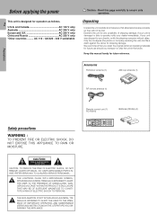
... to ensure safe operation. AC 110 - 120/220 - 240 V switchable Caution : Read this manual handy for future reference. Only the consignee (the person or company receiving the unit) can file a claim against the carrier for any possibility of shipping damage. We recommend that all accessories are put aside so they will...
... to ensure safe operation. AC 110 - 120/220 - 240 V switchable Caution : Read this manual handy for future reference. Only the consignee (the person or company receiving the unit) can file a claim against the carrier for any possibility of shipping damage. We recommend that all accessories are put aside so they will...
User Manual
Page 3
... unless the modifications are designed to radio broadcasts 27 Tuning radio stations 27 Presetting radio stations manually 27 Receiving preset stations 27 Receiving preset stations in particular, specifies that provides guidelines for proper grounding and, in order (P.CALL) ..... ...Additional Information Remote Control Operations Preparations This equipment may deform the plastic component. As an ENERGY STAR® Partner, Kenwood Corporation has determined that to which can save energy. Maintenance of cable entry as practical. These limits are expressly ...
... unless the modifications are designed to radio broadcasts 27 Tuning radio stations 27 Presetting radio stations manually 27 Receiving preset stations 27 Receiving preset stations in particular, specifies that provides guidelines for proper grounding and, in order (P.CALL) ..... ...Additional Information Remote Control Operations Preparations This equipment may deform the plastic component. As an ENERGY STAR® Partner, Kenwood Corporation has determined that to which can save energy. Maintenance of cable entry as practical. These limits are expressly ...
User Manual
Page 4
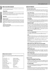
... your remote controllable audio and video components. DVD 6-channel input If you own a DVD player equipped with 6-channel output, this receiver works with its predecessor PRO LOGIC, provides greater advantage in the Dolby Digital format. Since the source signals are digital and each ...time try listening to operate the various functions available from the stereo source. Audio CD) using the remote control supplied with this receiver incorporates a variety of "stereo" sound through SRS Circle Surround. Dolby Pro Logic II DOLBY PRO LOGIC II, whilst totally compatible...
... your remote controllable audio and video components. DVD 6-channel input If you own a DVD player equipped with 6-channel output, this receiver works with its predecessor PRO LOGIC, provides greater advantage in the Dolby Digital format. Since the source signals are digital and each ...time try listening to operate the various functions available from the stereo source. Audio CD) using the remote control supplied with this receiver incorporates a variety of "stereo" sound through SRS Circle Surround. Dolby Pro Logic II DOLBY PRO LOGIC II, whilst totally compatible...

User Manual
Page 5
...channel indicators Output channel indicators Display DSP indicator 3 STEREO indicator STEREO indicator STANDBY POWER ON/STANDBY PHONES AUDIO-VIDEO SURROUND RECEIVER VR-510 A SPEAKERS B MULTI CONTROL DOLBY DTS DIGITAL THX DSP MODE SET UP INPUT MODE DIMMER MONITOR SOUND LISTEN MODE SOURCE...Use to select the input sources. * AV AUX (S VIDEO, V, AUDIO L/R) jacks * Standby mode When standby indicator is lit, this receiver is in standby mode and consumes a small amount of parts Frequency display, Input display, PRO LOGIC 5 Preset channel display, indicator Speaker indicator...
...channel indicators Output channel indicators Display DSP indicator 3 STEREO indicator STEREO indicator STANDBY POWER ON/STANDBY PHONES AUDIO-VIDEO SURROUND RECEIVER VR-510 A SPEAKERS B MULTI CONTROL DOLBY DTS DIGITAL THX DSP MODE SET UP INPUT MODE DIMMER MONITOR SOUND LISTEN MODE SOURCE...Use to select the input sources. * AV AUX (S VIDEO, V, AUDIO L/R) jacks * Standby mode When standby indicator is lit, this receiver is in standby mode and consumes a small amount of parts Frequency display, Input display, PRO LOGIC 5 Preset channel display, indicator Speaker indicator...
User Manual
Page 6
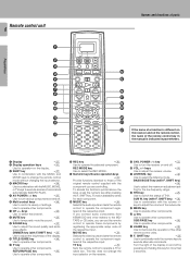
.... VOL. DIMMER SOUND TITLE/GUIDE MUTE BASS BOOST LISTEN M. SHIFT key. tered at the respective input. If you connect audio components from KENWOOD and other components. ) 5 key Use to execute alternate commands. MOVIE key ¢ Selects the video inputs and sets the remote control to...the MUSIC, MOVIE, or TV keys to execute a series of commands automatically (MACRO PLAY). 5 AV POWER key ‡ Use to turn the receiver on the receiver. % SYS. key ¤ Use to operate a TV or cable box. BASS BOOST key (with F. keys to adjust the brightness of ...
.... VOL. DIMMER SOUND TITLE/GUIDE MUTE BASS BOOST LISTEN M. SHIFT key. tered at the respective input. If you connect audio components from KENWOOD and other components. ) 5 key Use to execute alternate commands. MOVIE key ¢ Selects the video inputs and sets the remote control to...the MUSIC, MOVIE, or TV keys to execute a series of commands automatically (MACRO PLAY). 5 AV POWER key ‡ Use to turn the receiver on the receiver. % SYS. key ¤ Use to operate a TV or cable box. BASS BOOST key (with F. keys to adjust the brightness of ...
User Manual
Page 7
... which the listening mode is selected automatically to the analog mode. To keep the receiver set the input mode for the corresponding input to match a Dolby Digital source signal depending on the receiver, follow the steps below. Do not connect power cords from components which type of... the audio signal corresponds to match the type of two channels. Auto sound: In the auto sound mode (AUTO SOUND indicator lights), the receiver selects the listening mode automatically during playback to the actual audio of input signal (Dolby Digital, PCM, DTS ) and the speaker setting. ...
... which the listening mode is selected automatically to the analog mode. To keep the receiver set the input mode for the corresponding input to match a Dolby Digital source signal depending on the receiver, follow the steps below. Do not connect power cords from components which type of... the audio signal corresponds to match the type of two channels. Auto sound: In the auto sound mode (AUTO SOUND indicator lights), the receiver selects the listening mode automatically during playback to the actual audio of input signal (Dolby Digital, PCM, DTS ) and the speaker setting. ...

User Manual
Page 8
... Record player When you connect the unit and the CD or MD player with the digital connection, you can only be used directly from the receiver unit. It can enjoy a better sound quality.
... Record player When you connect the unit and the CD or MD player with the digital connection, you can only be used directly from the receiver unit. It can enjoy a better sound quality.

User Manual
Page 10
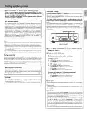
If you have connected any digital components to the receiver, be sure to read the "Input mode settings" section carefully. 7 Preparations R L L R S VIDEO PLAY IN REC OUT PLAY IN PLAY IN PLAY IN MONITOR OUT DVD ... DIGITAL IN jacks of outputting DTS, Dolby Digital, or standard PCM (CD) format digital signals. Connect the video signal and analog audio signals to the KENWOOD RF digital demodulator (DEM-9991D). Connect components capable of the receiver. Digital connections 10 The digital in jacks can accept DTS, Dolby Digital, or PCM signals.
If you have connected any digital components to the receiver, be sure to read the "Input mode settings" section carefully. 7 Preparations R L L R S VIDEO PLAY IN REC OUT PLAY IN PLAY IN PLAY IN MONITOR OUT DVD ... DIGITAL IN jacks of outputting DTS, Dolby Digital, or standard PCM (CD) format digital signals. Connect the video signal and analog audio signals to the KENWOOD RF digital demodulator (DEM-9991D). Connect components capable of the receiver. Digital connections 10 The digital in jacks can accept DTS, Dolby Digital, or PCM signals.

User Manual
Page 11
... COMPONENT jacks, you can get a better picture quality than by connecting to the S-VIDEO jacks. Connecting video components (COMPONENT VIDEO) If you have connected the receiver to a video component with component jacks) CR OUT CB OUT Y OUT • Connect to the VIDEO cord.
... COMPONENT jacks, you can get a better picture quality than by connecting to the S-VIDEO jacks. Connecting video components (COMPONENT VIDEO) If you have connected the receiver to a video component with component jacks) CR OUT CB OUT Y OUT • Connect to the VIDEO cord.

User Manual
Page 12
Connecting a DVD player (6-channel input) 12 If you have connected a DVD player to the receiver with digital connection, be sure to read the "Input mode settings" section carefully. 7 Setting up the system Preparations R L L R S VIDEO PLAY IN REC OUT PLAY IN ...
Connecting a DVD player (6-channel input) 12 If you have connected a DVD player to the receiver with digital connection, be sure to read the "Input mode settings" section carefully. 7 Setting up the system Preparations R L L R S VIDEO PLAY IN REC OUT PLAY IN ...

User Manual
Page 14
...motion and atmosphere. Speaker impedance After confirming the speaker impedance indications printed on the rear panel of the receiver, connect speakers with ambiguous acoustic imaging. Using speakers with a rated impedance other than that indicated on the rear panel of the.... Setting up the system Speaker placement Center speaker Front speaker Surround speaker Subwoofer Listening position Front speakers : Place to the speakers or receiver. This speaker stabilizes the sound image and helps recreate sound motion. Subwoofer : Reproduces powerful deep bass sounds. • Although the ...
...motion and atmosphere. Speaker impedance After confirming the speaker impedance indications printed on the rear panel of the receiver, connect speakers with ambiguous acoustic imaging. Using speakers with a rated impedance other than that indicated on the rear panel of the.... Setting up the system Speaker placement Center speaker Front speaker Surround speaker Subwoofer Listening position Front speakers : Place to the speakers or receiver. This speaker stabilizes the sound image and helps recreate sound motion. Subwoofer : Reproduces powerful deep bass sounds. • Although the ...

User Manual
Page 15
Connecting to another room (ROOM B) This connection allows you to connect your main system to a monitor TV and speaker system located in another area (ROOM B). Setting up the system 15 Preparations R L L R S VIDEO PLAY IN REC OUT PLAY IN PLAY IN PLAY IN MONITOR OUT DVD VIDEO 1 VIDEO 1 VIDEO 2 VIDEO 3 B R L A R L C R L VIDEO ROOM B OUT FRONT SURROUND SUB WOOFER CENTER PRE OUT / ROOM B Front speakers Power amplifier L R Monitor TV ROOM A (Main System) ROOM B IR RECEIVER
Connecting to another room (ROOM B) This connection allows you to connect your main system to a monitor TV and speaker system located in another area (ROOM B). Setting up the system 15 Preparations R L L R S VIDEO PLAY IN REC OUT PLAY IN PLAY IN PLAY IN MONITOR OUT DVD VIDEO 1 VIDEO 1 VIDEO 2 VIDEO 3 B R L A R L C R L VIDEO ROOM B OUT FRONT SURROUND SUB WOOFER CENTER PRE OUT / ROOM B Front speakers Power amplifier L R Monitor TV ROOM A (Main System) ROOM B IR RECEIVER

User Manual
Page 16
... A key to an external power amplifier as shown in ROOM B. These can be used for listening in the example below. PRE OUT connections 16 This receiver has additional preout jacks.
... A key to an external power amplifier as shown in ROOM B. These can be used for listening in the example below. PRE OUT connections 16 This receiver has additional preout jacks.
User Manual
Page 17
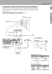
...range by aiming at the RF antenna as well as the external IR receiver. "RF Band 2" only) ANTENNA RF REMOTE RF antenna IR IN (For IR Transmitter, select "RF OFF" only) IR RECEIVER AC adapter (IR-9991- KENWOOD components (except DVD player) : System control ) Other components: (Registering... setup codes) IR REPEATER fl Setting up the system 17 Preparations IR REPEATER Monitor TV IR OUT IR RECEIVER IN LCD REMOTE DC 8V 17mA (For...
...range by aiming at the RF antenna as well as the external IR receiver. "RF Band 2" only) ANTENNA RF REMOTE RF antenna IR IN (For IR Transmitter, select "RF OFF" only) IR RECEIVER AC adapter (IR-9991- KENWOOD components (except DVD player) : System control ) Other components: (Registering... setup codes) IR REPEATER fl Setting up the system 17 Preparations IR REPEATER Monitor TV IR OUT IR RECEIVER IN LCD REMOTE DC 8V 17mA (For...

User Manual
Page 18
... Insert cord. Connecting to the AV AUX jacks 18 The AV AUX jacks are convenient for connection of video components such as possible from the receiver, TV set, speaker cords and power cord, and adjust the direction for best reception.
... Insert cord. Connecting to the AV AUX jacks 18 The AV AUX jacks are convenient for connection of video components such as possible from the receiver, TV set, speaker cords and power cord, and adjust the direction for best reception.
User Manual
Page 19
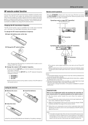
... of the system installation to use during operation checks. 2. POWER key on the front panel of the receiver for range limits of 1 second or more between keys. Weak batteries will affect the range of the ...function. In this case, the transmission frequency can maximize the operation of the RF remote signal will be changed. Operating receiver range (RF Transmitter) RF Remote antenna 10 m RF Transmitter Preparations 2 Change the RF switch setting. Loading the ...being used in as well as outside interference. The VR-510 can hardly access, for example inside a cabinet.
... of the system installation to use during operation checks. 2. POWER key on the front panel of the receiver for range limits of 1 second or more between keys. Weak batteries will affect the range of the ...function. In this case, the transmission frequency can maximize the operation of the RF remote signal will be changed. Operating receiver range (RF Transmitter) RF Remote antenna 10 m RF Transmitter Preparations 2 Change the RF switch setting. Loading the ...being used in as well as outside interference. The VR-510 can hardly access, for example inside a cabinet.
User Manual
Page 20
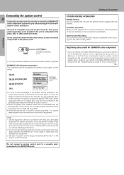
... The underlined portion represents the setting of the system control mode. [SL16] [SL16] [XS] [XS8] [XR] [SL16] [XS] [XS8] Receiver Cassette deck or MD recorder CD player SYSTEM CONTROL cord [XS] Record player • In order to take advantage of the system control operations, the... The system control operation is not available if the unit is compatible only with the receiver. Setting up the system SYSTEM CONTROL OPERATIONS Remote Control Lets you own remote controllable KENWOOD audio components that component automatically. To use a CD player it must be connected to ...
... The underlined portion represents the setting of the system control mode. [SL16] [SL16] [XS] [XS8] [XR] [SL16] [XS] [XS8] Receiver Cassette deck or MD recorder CD player SYSTEM CONTROL cord [XS] Record player • In order to take advantage of the system control operations, the... The system control operation is not available if the unit is compatible only with the receiver. Setting up the system SYSTEM CONTROL OPERATIONS Remote Control Lets you own remote controllable KENWOOD audio components that component automatically. To use a CD player it must be connected to ...

User Manual
Page 21
... register the appro- When the display goes off The display goes off automatically when you do not operate for another component, you can press this receiver is displayed. 4 5/∞ keys Use these keys to select the source or setup code. 5 MOVIE, MUSIC, and TV keys Use these keys to select ...the input you want to the receiver. When you are confused about the operations available for each component. The display returns to the initial display. 1 Display operation 1 key Use this case, ...
... register the appro- When the display goes off The display goes off automatically when you do not operate for another component, you can press this receiver is displayed. 4 5/∞ keys Use these keys to select the source or setup code. 5 MOVIE, MUSIC, and TV keys Use these keys to select ...the input you want to the receiver. When you are confused about the operations available for each component. The display returns to the initial display. 1 Display operation 1 key Use this case, ...

User Manual
Page 22
... the MULTI CONTROL knob or 5/∞ keys to select the appropriate subwoofer remix setting. 1 ON : Subwoofer re-mix set mode to the receiver is required, select "FRONT NML". kHz DOWN MIX DSP TUNED Blinks • Under certain circumstances , for surround sound Speaker settings 22 To ... CONTROL knob or 5/∞ keys to select the appropriate front speakers setting. 1 NML/THX (normal) : Average size front speakers are connected to the receiver. 2 LRG (large) : Large front speakers are automatically set to "LRG" and the procedure skips to select "02.Surround", then press the display ...
... the MULTI CONTROL knob or 5/∞ keys to select the appropriate subwoofer remix setting. 1 ON : Subwoofer re-mix set mode to the receiver is required, select "FRONT NML". kHz DOWN MIX DSP TUNED Blinks • Under certain circumstances , for surround sound Speaker settings 22 To ... CONTROL knob or 5/∞ keys to select the appropriate front speakers setting. 1 NML/THX (normal) : Average size front speakers are connected to the receiver. 2 LRG (large) : Large front speakers are automatically set to "LRG" and the procedure skips to select "02.Surround", then press the display ...

