Installation Instructions
Page 1
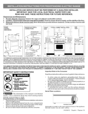
... 2-5/8"for models equipped withwarmer drawers, 3-1/2"for proper electrical supply, and the stability of the appliance. Remove all instructions contained in these installation instructions before connecting the gas & electrical supply to the Consumer Keep these instructions with door handle. As when using any appliance generating heat, there are listed in this manual is not followed exactly, a fire or electrical shock may be solid and level. Provide adequate clearances between the range and adjacent combustible surfaces...
... 2-5/8"for models equipped withwarmer drawers, 3-1/2"for proper electrical supply, and the stability of the appliance. Remove all instructions contained in these installation instructions before connecting the gas & electrical supply to the Consumer Keep these instructions with door handle. As when using any appliance generating heat, there are listed in this manual is not followed exactly, a fire or electrical shock may be solid and level. Provide adequate clearances between the range and adjacent combustible surfaces...
Installation Instructions
Page 2
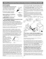
... closed loop or open door or ifa child climbs upon it forward. When installing Permanent Wiring, do not leave excess wire in Step 4c. ANTI-TIP BRACKET INSTALLATION INSTRUCTIONS - lb. Drill Pilot Holes & Fasten Bracket - Drill a 1/8" pilot hole where screws are secured in wood or cement fastened to be sure that screws do not permit grounding through neutral require a four (4) conductor power supply cord kit rated at an approximate...
... closed loop or open door or ifa child climbs upon it forward. When installing Permanent Wiring, do not leave excess wire in Step 4c. ANTI-TIP BRACKET INSTALLATION INSTRUCTIONS - lb. Drill Pilot Holes & Fasten Bracket - Drill a 1/8" pilot hole where screws are secured in wood or cement fastened to be sure that screws do not permit grounding through neutral require a four (4) conductor power supply cord kit rated at an approximate...
Installation Instructions
Page 3
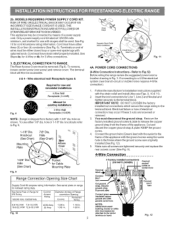
... installations A3llWowireedWfoarll Receptacle (10-5OR) NOTE: Range is shipped from the frame of electrical connection may be removed (Fig 9). Electrical failure or loss of the appliance. Connect the ground wire (Green) lead with the ground screw using the same hole in Fig. 3. MODELS REQUIRING POWER SUPPLY CORD KIT. The Rear Access Cover must disconnect the ground strap. See serial plate on range for kilowatt rating data, See Serial Plate on brock Connect...
... installations A3llWowireedWfoarll Receptacle (10-5OR) NOTE: Range is shipped from the frame of electrical connection may be removed (Fig 9). Electrical failure or loss of the appliance. Connect the ground wire (Green) lead with the ground screw using the same hole in Fig. 3. MODELS REQUIRING POWER SUPPLY CORD KIT. The Rear Access Cover must disconnect the ground strap. See serial plate on range for kilowatt rating data, See Serial Plate on brock Connect...
Installation Instructions
Page 4
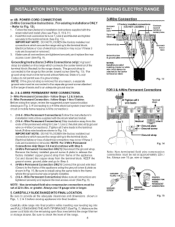
... use 10 ga. Tighten all connections are tightened securely and replace the rear access cover (See Fig. 9). POWER CORD CONNECTIONS (3-Wire Connection Instructions. Insert the end connectors for Line 1, Line 2 and Neutral and tighten securely to the range by the center, lowest screw (See Fig. 13). Grounding Instructions (3-Wire Connections only): Aground strap is removed for Line 1, Line 2, Neutral (also strip ground wire on 4-Wire Connections). If connecting to the range chassis. Wire Permanent Connections) Follow the manufacturer's installation instructions supplied...
... use 10 ga. Tighten all connections are tightened securely and replace the rear access cover (See Fig. 9). POWER CORD CONNECTIONS (3-Wire Connection Instructions. Insert the end connectors for Line 1, Line 2 and Neutral and tighten securely to the range by the center, lowest screw (See Fig. 13). Grounding Instructions (3-Wire Connections only): Aground strap is removed for Line 1, Line 2, Neutral (also strip ground wire on 4-Wire Connections). If connecting to the range chassis. Wire Permanent Connections) Follow the manufacturer's installation instructions supplied...


