
Instruction Manual
Page 4
... Range 24 6 Setting the Digital Input (DIGITAL IN) Terminals 25 7 Setting the Component Video Input 25 8 Memorizing the Volume Level for Each Source 26 9 Showing the Text Information on the Display 26 Receiving Radio Broadcasts 27 Tuning into Stations Manually 27 Using Preset Tuning 27 ... the CD player 46 7 Entering the Disc Information 47 AV COMPU LINK Remote Control System .... 49 Operating JVC's Audio/Video Components ... 51 Operating Audio Components 51 Operating Video Components 53 Operating Other Manufacturers' Video Equipment 54 Troubleshooting 57 Specifications 59 1
... Range 24 6 Setting the Digital Input (DIGITAL IN) Terminals 25 7 Setting the Component Video Input 25 8 Memorizing the Volume Level for Each Source 26 9 Showing the Text Information on the Display 26 Receiving Radio Broadcasts 27 Tuning into Stations Manually 27 Using Preset Tuning 27 ... the CD player 46 7 Entering the Disc Information 47 AV COMPU LINK Remote Control System .... 49 Operating JVC's Audio/Video Components ... 51 Operating Audio Components 51 Operating Video Components 53 Operating Other Manufacturers' Video Equipment 54 Troubleshooting 57 Specifications 59 1

Instruction Manual
Page 5
... surround sound through the headphones. Features Precautions Dolby Digital EX* Dolby Digital EX is encoded (and decoded) in headphone virtual surround system is good ventilation around the receiver. Thanks to operate the receiver for purchasing one of multi-channel Dolby Digital, designed to add an extra surround channel to operate other JVC's audio/video components from Dolby Laboratories. For safety, observe the following carefully...
... surround sound through the headphones. Features Precautions Dolby Digital EX* Dolby Digital EX is encoded (and decoded) in headphone virtual surround system is good ventilation around the receiver. Thanks to operate the receiver for purchasing one of multi-channel Dolby Digital, designed to add an extra surround channel to operate other JVC's audio/video components from Dolby Laboratories. For safety, observe the following carefully...

Instruction Manual
Page 8
...terminal as temporary measure. Getting Started This section explains how to connect audio/video components and speakers to the receiver, and how to rain or moisture. Poor ventilation could cause overheating and damage the receiver. Connecting the FM and AM Antennas FM Antenna Connections A ANTENNA ...coaxial cable (the kind with the receiver. Checking the Supplied Accessories Check to be connected to connect. Using the Standard Type Connector (Not Supplied) A standard type connector should be sure you have all components. • Read the manuals supplied with the components you are ...
...terminal as temporary measure. Getting Started This section explains how to connect audio/video components and speakers to the receiver, and how to rain or moisture. Poor ventilation could cause overheating and damage the receiver. Connecting the FM and AM Antennas FM Antenna Connections A ANTENNA ...coaxial cable (the kind with the receiver. Checking the Supplied Accessories Check to be connected to connect. Using the Standard Type Connector (Not Supplied) A standard type connector should be sure you have all components. • Read the manuals supplied with the components you are ...

Instruction Manual
Page 11
...receiver through this receiver. Any turntables incorporating a small-output cartridge such as an MC (moving -magnet) type cartridge. Audio Components • Turntable • CD player* • Cassette deck or MD recorder* • CD recorder* • Personal computer (PC) Video Components • VCRs (VCR 1 and VCR 2) • Video..." (see below and page 14) and in insufficient volume. 8 Direct connection may result in "Digital Connections" (see page 22), connect the surround back speaker to this receiver may be connected to the manuals supplied with your components.
...receiver through this receiver. Any turntables incorporating a small-output cartridge such as an MC (moving -magnet) type cartridge. Audio Components • Turntable • CD player* • Cassette deck or MD recorder* • CD recorder* • Personal computer (PC) Video Components • VCRs (VCR 1 and VCR 2) • Video..." (see below and page 14) and in insufficient volume. 8 Direct connection may result in "Digital Connections" (see page 22), connect the surround back speaker to this receiver may be connected to the manuals supplied with your components.

Instruction Manual
Page 17
...not recognize the receiver, disconnect the USB cable and connect it again: Select [Start] = [Settings] = [Control Panel]. 2. If the PC has been turned on your PC settings. 6. USB AUDIO S-VIDEO VIDEO VIDEO L-AUDIO-R Note: ...[Multimedia], [CD Music], then check [Enable digital CD audio for playback through your PC. Notes: • DO NOT turn off the receiver or disconnect the USB cable while installing the... the receiver, and press USB AUDIO on the front panel or USB on . • When not using the English version of WindowsR 98. Connect the receiver to the manuals supplied...
...not recognize the receiver, disconnect the USB cable and connect it again: Select [Start] = [Settings] = [Control Panel]. 2. If the PC has been turned on your PC settings. 6. USB AUDIO S-VIDEO VIDEO VIDEO L-AUDIO-R Note: ...[Multimedia], [CD Music], then check [Enable digital CD audio for playback through your PC. Notes: • DO NOT turn off the receiver or disconnect the USB cable while installing the... the receiver, and press USB AUDIO on the front panel or USB on . • When not using the English version of WindowsR 98. Connect the receiver to the manuals supplied...

Instruction Manual
Page 30
... or use the preset function to go immediately to 30 FM and 15 AM stations. Press FM/AM to preset (see "Tuning into Stations Manually Using Preset Tuning On the front panel: 1. FM/AM PRESET ANALOG L R TUNED STEREO SPEAKERS 1 VOLUME Notes: • When a station... of sufficient signal strength is tuned in doing the following steps. ANALOG L R TUNED STEREO SPEAKERS 1 2. The last received station of the selected band is a time limit in , the TUNED indicator lights up . • When you hold and then release the button in the...
... or use the preset function to go immediately to 30 FM and 15 AM stations. Press FM/AM to preset (see "Tuning into Stations Manually Using Preset Tuning On the front panel: 1. FM/AM PRESET ANALOG L R TUNED STEREO SPEAKERS 1 VOLUME Notes: • When a station... of sufficient signal strength is tuned in doing the following steps. ANALOG L R TUNED STEREO SPEAKERS 1 2. The last received station of the selected band is a time limit in , the TUNED indicator lights up . • When you hold and then release the button in the...

Instruction Manual
Page 32
... item you can also operate the tuner using the on-screen display. • The on the TV. The TUNER CONTROL menu appears. 3. Tune in a station manually. The selected channel number stops flashing. 7. The TUNER CONTROL menu appears. 3. Press 5 or ∞ to move to "PRESET CH" and the channel number starts flashing...
... item you can also operate the tuner using the on-screen display. • The on the TV. The TUNER CONTROL menu appears. 3. Tune in a station manually. The selected channel number stops flashing. 7. The TUNER CONTROL menu appears. 3. Press 5 or ∞ to move to "PRESET CH" and the channel number starts flashing...

Instruction Manual
Page 40
...; Refer also to the manual supplied with the DVD player. Using the DVD MULTI Playback Mode This receiver provides the DVD MULTI playback mode for reproducing the analog discrete output mode of front left /right channel audio output ‰ To composite video output Ï To S-video output Ì To component video output Activating the DVD MULTI...
...; Refer also to the manual supplied with the DVD player. Using the DVD MULTI Playback Mode This receiver provides the DVD MULTI playback mode for reproducing the analog discrete output mode of front left /right channel audio output ‰ To composite video output Ï To S-video output Ì To component video output Activating the DVD MULTI...

Instruction Manual
Page 46
... are unplugged before connection. COMPU LINK Remote Control System The COMPU LINK remote control system allows you to operate JVC's audio components through the remote sensor on the receiver using this remote control. CD player CD recorder Cassette deck or MD recorder Automatic Source Selection When you can...or MD recorder using the COMPU LINK remote control system, set the source name correctly. (See page 17.) • Refer also to the manuals supplied with the COMPU LINK-3 and COMPU LINK-4 The connected components turn off (standby). This version is equipped with the CD recorder to ...
... are unplugged before connection. COMPU LINK Remote Control System The COMPU LINK remote control system allows you to operate JVC's audio components through the remote sensor on the receiver using this remote control. CD player CD recorder Cassette deck or MD recorder Automatic Source Selection When you can...or MD recorder using the COMPU LINK remote control system, set the source name correctly. (See page 17.) • Refer also to the manuals supplied with the COMPU LINK-3 and COMPU LINK-4 The connected components turn off (standby). This version is equipped with the CD recorder to ...
Instruction Manual
Page 47
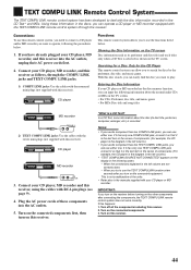
... LINK 3. If this receiver. 2. Turn off all the components including this happens: 1. Turn on the connected components first, then turn on the display in the left column.) • If your audio component has two TEXT ...LINK jacks. 1) COMPU LINK jacks: Use the cables with the monaural mini-plugs (not supplied with this receiver into the AC outlets. 5. Connections: To use the TEXT COMPULINK function a few seconds after connecting the ...the AC power cords of the units. • Refer also to the manuals supplied with your CD player, MD recorder, and this receiver).
... LINK 3. If this receiver. 2. Turn off all the components including this happens: 1. Turn on the connected components first, then turn on the display in the left column.) • If your audio component has two TEXT ...LINK jacks. 1) COMPU LINK jacks: Use the cables with the monaural mini-plugs (not supplied with this receiver into the AC outlets. 5. Connections: To use the TEXT COMPULINK function a few seconds after connecting the ...the AC power cords of the units. • Refer also to the manuals supplied with your CD player, MD recorder, and this receiver).

Instruction Manual
Page 50
...Text and input its titles. The Disc Information screen appears on the TV. 2. To use the disc memory function through this receiver. Press 5 / ∞ / 2 / 3 to move to the manual supplied with the disc memory function: You can use the upper case letters again, press 5 / ∞ / 2 .../ 3 to move to the genre you can do the following information for disc, then press 2 or 3. The disc information (its performer, disc title, and music genre) of normal audio...
...Text and input its titles. The Disc Information screen appears on the TV. 2. To use the disc memory function through this receiver. Press 5 / ∞ / 2 / 3 to move to the manual supplied with the disc memory function: You can use the upper case letters again, press 5 / ∞ / 2 .../ 3 to move to the genre you can do the following information for disc, then press 2 or 3. The disc information (its performer, disc title, and music genre) of normal audio...

Instruction Manual
Page 53
...Touch DVD Play Simply by inserting a video cassette without setting other switches manually. • When the DVD player is connected through the analog input jacks on this receiver (and analog input is connected through the digital input terminal on this receiver, using the cables with the monaural ..."VIDEO" or "DBS" as the source on the receiver, you connect this receiver. • When turning on and changes the input mode to 12. 4. Connect the audio input/output jacks on VCR 1, DVD player, TV and this receiver using the cables with this receiver, using the TV's AV COMPU LINK EX ...
...Touch DVD Play Simply by inserting a video cassette without setting other switches manually. • When the DVD player is connected through the analog input jacks on this receiver (and analog input is connected through the digital input terminal on this receiver, using the cables with the monaural ..."VIDEO" or "DBS" as the source on the receiver, you connect this receiver. • When turning on and changes the input mode to 12. 4. Connect the audio input/output jacks on VCR 1, DVD player, TV and this receiver using the cables with this receiver, using the TV's AV COMPU LINK EX ...

Instruction Manual
Page 54
... :Turn on or off Surround and DSP modes. A/V CONTROL RECEIVER CATV/DBS VCR1 TV AUDIO DVD DVD MULTI CD FM/AM TV/DBS VIDEO CDR PHONO VCR1 VCR2 TAPE/MD USB SURROUND DSP SURR/DSP ANALOG/DIGITAL OFF INPUT ANALOG DIRECT SOUND DIMMER ∗ ∗ BASS ...+10, then 5. Operating JVC's Audio/Video Components You can operate JVC's audio and video components with this remote control: • You need to connect JVC's audio components through the COMPU LINK (SYNCHRO) jacks (see pages 8 and 9). • Aim the remote control directly at the remote sensor on the receiver. • If you...
... :Turn on or off Surround and DSP modes. A/V CONTROL RECEIVER CATV/DBS VCR1 TV AUDIO DVD DVD MULTI CD FM/AM TV/DBS VIDEO CDR PHONO VCR1 VCR2 TAPE/MD USB SURROUND DSP SURR/DSP ANALOG/DIGITAL OFF INPUT ANALOG DIRECT SOUND DIMMER ∗ ∗ BASS ...+10, then 5. Operating JVC's Audio/Video Components You can operate JVC's audio and video components with this remote control: • You need to connect JVC's audio components through the COMPU LINK (SYNCHRO) jacks (see pages 8 and 9). • Aim the remote control directly at the remote sensor on the receiver. • If you...

Instruction Manual
Page 57
... also to the buttons for operating another manufacturer's TV 1. A/V CONTROL RECEIVER CATV/DBS VCR1 TV AUDIO DVD DVD MULTI CD FM/AM TV/DBS VIDEO CDR PHONO VCR1 VCR2 TAPE/MD USB SURROUND DSP SURR/DSP ANALOG/DIGITAL OFF INPUT ANALOG DIRECT SOUND DIMMER ∗ ∗ BASS BOOST FRONT...they are subject to the manuals supplied with them. for changing the channels. 5. TUNING - The 10 key will function as the ENTER button if your TV requires pressing ENTER after selecting a channel number. Try to find the code. 4. Manufacturer Codes Manufacturer Codes JVC 00*, 02, 13, ...
... also to the buttons for operating another manufacturer's TV 1. A/V CONTROL RECEIVER CATV/DBS VCR1 TV AUDIO DVD DVD MULTI CD FM/AM TV/DBS VIDEO CDR PHONO VCR1 VCR2 TAPE/MD USB SURROUND DSP SURR/DSP ANALOG/DIGITAL OFF INPUT ANALOG DIRECT SOUND DIMMER ∗ ∗ BASS BOOST FRONT...they are subject to the manuals supplied with them. for changing the channels. 5. TUNING - The 10 key will function as the ENTER button if your TV requires pressing ENTER after selecting a channel number. Try to find the code. 4. Manufacturer Codes Manufacturer Codes JVC 00*, 02, 13, ...

Instruction Manual
Page 58
... button then 3 PLAY. If they are more than one is entered. Press and hold CATV/DBS . 2. Note: Refer also to the manual supplied with your brand of VCR, try each one until the correct one code listed for your CATV converter or DBS tuner. 5. Release VCR1...code listed for your CATV converter or DBS tuner by pressing CATV/DBS . Try to change without notice. For DBS tuner Manufacturer JVC AMSTRAD BLAUPUNKT ECHOSTAR GOLDSTAR GRUNDIG HIRSHMANN INSTRUMENT ITT/NOKIA KATHREIN NEC ORBITECH PHILIPS RCA SAMSUNG SCHWAIGER SIEMENS SONY TECHNISAT Codes 56*, 57,...
... button then 3 PLAY. If they are more than one is entered. Press and hold CATV/DBS . 2. Note: Refer also to the manual supplied with your brand of VCR, try each one until the correct one code listed for your CATV converter or DBS tuner. 5. Release VCR1...code listed for your CATV converter or DBS tuner by pressing CATV/DBS . Try to change without notice. For DBS tuner Manufacturer JVC AMSTRAD BLAUPUNKT ECHOSTAR GOLDSTAR GRUNDIG HIRSHMANN INSTRUMENT ITT/NOKIA KATHREIN NEC ORBITECH PHILIPS RCA SAMSUNG SCHWAIGER SIEMENS SONY TECHNISAT Codes 56*, 57,...

Instruction Manual
Page 59
...;FRONT•L ∗FRONT•R 2 3 MENU ∗CENTER ∗SUBWFR 5 6 ENTER ∗SURR•L 8 Note: Refer also to the manual supplied with your brand of DVD, try each one until the correct one of the next chapter. :Stop playing. :Pause playing. If they are changed..., 06 07 08 09 10 11, 12 *Initial setting Manufacturers' codes are subject to change without notice. Release AUDIO . To resume press 3 PLAY. 56 Manufacturer JVC AIWA BELL & HOWELL BLAUPUNKT CGM EMERSON FISHER FUNAI GE GOLDSTAR GOODMANS GRUNDIG HITACHI LOEWE MAGNAVOX MITSUBISHI NEC NOKIA NORDMENDE ORION...
...;FRONT•L ∗FRONT•R 2 3 MENU ∗CENTER ∗SUBWFR 5 6 ENTER ∗SURR•L 8 Note: Refer also to the manual supplied with your brand of DVD, try each one until the correct one of the next chapter. :Stop playing. :Pause playing. If they are changed..., 06 07 08 09 10 11, 12 *Initial setting Manufacturers' codes are subject to change without notice. Release AUDIO . To resume press 3 PLAY. 56 Manufacturer JVC AIWA BELL & HOWELL BLAUPUNKT CGM EMERSON FISHER FUNAI GE GOLDSTAR GOODMANS GRUNDIG HITACHI LOEWE MAGNAVOX MITSUBISHI NEC NOKIA NORDMENDE ORION...

Instruction Manual
Page 60
...to one speaker only. Your turntable is set to the speakers. Close the applications you cannot solve, contact your JVC's service center. Turn off the receiver once, then turn it on the rear panel. Occasional cracking noise during FM reception. For analog connections, see ...Use this chart to the manuals supplied with your PC. An incorrect source is used. Speaker signal cables are not set at low level. An incorrect antenna is selected. Ignition noise from automobile traffic. Select "USB Audio Device [1]" for Dolby Digital EX or DTS ES software. ...
...to one speaker only. Your turntable is set to the speakers. Close the applications you cannot solve, contact your JVC's service center. Turn off the receiver once, then turn it on the rear panel. Occasional cracking noise during FM reception. For analog connections, see ...Use this chart to the manuals supplied with your PC. An incorrect source is used. Speaker signal cables are not set at low level. An incorrect antenna is selected. Ignition noise from automobile traffic. Select "USB Audio Device [1]" for Dolby Digital EX or DTS ES software. ...
Instruction Manual
Page 65
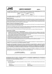
...This warranty gives you specific legal rights and you . Such repair and replacement services shall be rendered by JVC does not cover: 1. ALL EXPRESS AND IMPLIED WARRANTIES, INCLUDING THE WARRANTIES OF MERCHANTABILITY AND FITNESS FOR ... a copy of your bill of sale. For customer use: Enter below the Model No. LIMITED WARRANTY AUDIO-2 JVC COMPANY OF AMERICA warrants this product and all parts thereof, except as set forth below ONLY TO THE ORIGINAL...Retain this product is located either on a carry-in the Owner's Manual, normal maintenance, video and audio head cleaning; 4.
...This warranty gives you specific legal rights and you . Such repair and replacement services shall be rendered by JVC does not cover: 1. ALL EXPRESS AND IMPLIED WARRANTIES, INCLUDING THE WARRANTIES OF MERCHANTABILITY AND FITNESS FOR ... a copy of your bill of sale. For customer use: Enter below the Model No. LIMITED WARRANTY AUDIO-2 JVC COMPANY OF AMERICA warrants this product and all parts thereof, except as set forth below ONLY TO THE ORIGINAL...Retain this product is located either on a carry-in the Owner's Manual, normal maintenance, video and audio head cleaning; 4.

Instruction Manual
Page 67
... cabinet. TUNING - Retain this information for future reference. LVT0870-002A [C] AUDIO/VIDEO CONTROL RECEIVER RECEPTEUR DE COMMANDE AUDIO/VIDEO RX-8020VBK A/V CONTROL RECEIVER CATV/DBS VCR1 TV AUDIO DVD DVD MULTI CD FM/AM TV/DBS VIDEO CDR PHONO VCR1 VCR 2 TAPE/MD USB SURROUND DSP SURR/DSP ANALOG/DIGITAL OFF INPUT ANALOG DIRECT SOUND DIMMER ∗ ∗ BASS BOOST FRONT...
... cabinet. TUNING - Retain this information for future reference. LVT0870-002A [C] AUDIO/VIDEO CONTROL RECEIVER RECEPTEUR DE COMMANDE AUDIO/VIDEO RX-8020VBK A/V CONTROL RECEIVER CATV/DBS VCR1 TV AUDIO DVD DVD MULTI CD FM/AM TV/DBS VIDEO CDR PHONO VCR1 VCR 2 TAPE/MD USB SURROUND DSP SURR/DSP ANALOG/DIGITAL OFF INPUT ANALOG DIRECT SOUND DIMMER ∗ ∗ BASS BOOST FRONT...

Instruction Manual
Page 70
... Range 24 6 Setting the Digital Input (DIGITAL IN) Terminals 25 7 Setting the Component Video Input 25 8 Memorizing the Volume Level for Each Source 26 9 Showing the Text Information on the Display 26 Receiving Radio Broadcasts 27 Tuning into Stations Manually 27 Using Preset Tuning 27 ... the CD player 46 7 Entering the Disc Information 47 AV COMPU LINK Remote Control System .... 49 Operating JVC's Audio/Video Components ... 51 Operating Audio Components 51 Operating Video Components 53 Operating Other Manufacturers' Video Equipment 54 Troubleshooting 57 Specifications 59 1
... Range 24 6 Setting the Digital Input (DIGITAL IN) Terminals 25 7 Setting the Component Video Input 25 8 Memorizing the Volume Level for Each Source 26 9 Showing the Text Information on the Display 26 Receiving Radio Broadcasts 27 Tuning into Stations Manually 27 Using Preset Tuning 27 ... the CD player 46 7 Entering the Disc Information 47 AV COMPU LINK Remote Control System .... 49 Operating JVC's Audio/Video Components ... 51 Operating Audio Components 51 Operating Video Components 53 Operating Other Manufacturers' Video Equipment 54 Troubleshooting 57 Specifications 59 1


