Instructions
Page 3
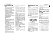
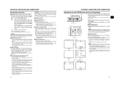
... and electrical safety. offices or theatres z urban outdoors In order to the presence of mains cable is : JVC Technology Centre Europe GmbH P.O. Caution: Where there are subject to provide reasonable protection against harmful interference in the literature... be placed close to correct the interference by turning the equipment off and appropriate one or more of the following length: Camera Port DC INPUT INPUT1/2 LINE OUTPUT PHONES 1/2 VIDEO/Y, PB, PR IEEE1394 (HDV/DV) Cable Exclusive Cable Shielded Cable Shielded Cable Shielded Cable Shielded Cable Exclusive Cable Length 2...
... and electrical safety. offices or theatres z urban outdoors In order to the presence of mains cable is : JVC Technology Centre Europe GmbH P.O. Caution: Where there are subject to provide reasonable protection against harmful interference in the literature... be placed close to correct the interference by turning the equipment off and appropriate one or more of the following length: Camera Port DC INPUT INPUT1/2 LINE OUTPUT PHONES 1/2 VIDEO/Y, PB, PR IEEE1394 (HDV/DV) Cable Exclusive Cable Shielded Cable Shielded Cable Shielded Cable Shielded Cable Exclusive Cable Length 2...
Instructions
Page 4
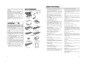
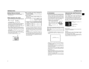
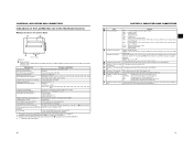
... This camcorder supports HDV 720p format. (HDV 720p, 480p, 576p) HDV and are not used in the unit. • Recording check function for convenient recording review function • Camera section designed with 1,110,000 effective pixels employed. Component output is a HDV/DV video system format camera recorder....and user's bits. • Built-in large 3.5" color LCD display In addition to manufacturing dispersion of copyright holders. • JVC cannot assume liabilities that both 60 Hz/50 Hz HD or HDTV signals. Digital signal processing for settings, and alarm indications. &#...
... This camcorder supports HDV 720p format. (HDV 720p, 480p, 576p) HDV and are not used in the unit. • Recording check function for convenient recording review function • Camera section designed with 1,110,000 effective pixels employed. Component output is a HDV/DV video system format camera recorder....and user's bits. • Built-in large 3.5" color LCD display In addition to manufacturing dispersion of copyright holders. • JVC cannot assume liabilities that both 60 Hz/50 Hz HD or HDTV signals. Digital signal processing for settings, and alarm indications. &#...
Instructions
Page 5
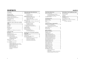
...Balance Adjustment 45 • White Balance Adjustment • Full Auto White Balance (FAW) SETTING AND ADJUSTMENTS BEFORE SHOOTING Setting the Video Format 46 Camera Settings 47 Screen Size (4:3/16:9) Mode Selection 47 Audio Input Signal Selection 48 • Selecting the CH-2 channel input connector ...60 MENU SCREENS Menu Screen Configuration 61 Setting Menu Screens 62 TOP MENU Screen 63 VIDEO FORMAT Menu Screen 64 CAMERA OPERATION Menu Screen 66 CAMERA PROCESS [1/2] Menu Screen 67 CAMERA PROCESS [2/2] Menu Screen 68 ADVANCED PROCESS Menu Screen 69 COLOR MATRIX ADJUST Menu Screen...
...Balance Adjustment 45 • White Balance Adjustment • Full Auto White Balance (FAW) SETTING AND ADJUSTMENTS BEFORE SHOOTING Setting the Video Format 46 Camera Settings 47 Screen Size (4:3/16:9) Mode Selection 47 Audio Input Signal Selection 48 • Selecting the CH-2 channel input connector ...60 MENU SCREENS Menu Screen Configuration 61 Setting Menu Screens 62 TOP MENU Screen 63 VIDEO FORMAT Menu Screen 64 CAMERA OPERATION Menu Screen 66 CAMERA PROCESS [1/2] Menu Screen 67 CAMERA PROCESS [2/2] Menu Screen 68 ADVANCED PROCESS Menu Screen 69 COLOR MATRIX ADJUST Menu Screen...
Instructions
Page 6
... INTRODUCTION Routine and Periodical Mainte- Avoid excessive repeated use of cleaning ery 5 hours ery 20 to maintain the video and audio quality at your nearest JVC-authorized service agent. Time management The accumulated running time of mechanical parts by transformers, motors, etc., or near... dirt or dust; • with a device other than specified. Adhere to remove the detergent. • The camera may occur. Do not use the camcorder with the connector covers on when you use the provided power cord with high humidity or moisture; • subject to...
... INTRODUCTION Routine and Periodical Mainte- Avoid excessive repeated use of cleaning ery 5 hours ery 20 to maintain the video and audio quality at your nearest JVC-authorized service agent. Time management The accumulated running time of mechanical parts by transformers, motors, etc., or near... dirt or dust; • with a device other than specified. Adhere to remove the detergent. • The camera may occur. Do not use the camcorder with the connector covers on when you use the provided power cord with high humidity or moisture; • subject to...
Instructions
Page 7
...recording and storage of videotapes. • Take care of the conditions of the tape edges. Head drum Video tape Do not leave the videocassette inserted when moving the camera under conditions where the temperature of light around a bright light or object (called "smear") when shooting ...to protect the required recording in distortion of the following batteries. • BN-V428, BN-V438 Videocassette to be Used • Use JVC's videocassette tapes marked with little humidity and good ventilation where mould does not form. • After a videocassette tape has been used upside ...
...recording and storage of videotapes. • Take care of the conditions of the tape edges. Head drum Video tape Do not leave the videocassette inserted when moving the camera under conditions where the temperature of light around a bright light or object (called "smear") when shooting ...to protect the required recording in distortion of the following batteries. • BN-V428, BN-V438 Videocassette to be Used • Use JVC's videocassette tapes marked with little humidity and good ventilation where mould does not form. • After a videocassette tape has been used upside ...
Instructions
Page 10
... be EE monitored. When the setting value starts blinking, turn the power on the switch position as menu operation buttons. X See "Camera Settings" on the CAMERA OPERATION menu screen. The boosting level differs depending on again. A : Switch into white balance mode memorized in the main body of...h on the OTHERS [1/2] menu screen. X See page 71. In the FAW mode, video color temperatures are selectable with the SWITCH MODE menu screen. e[POWER] Power ON/OFF switch Switch that the camcorder will be changed when this dial is turned 1 click up or down in the normal screen...
... be EE monitored. When the setting value starts blinking, turn the power on the switch position as menu operation buttons. X See "Camera Settings" on the CAMERA OPERATION menu screen. The boosting level differs depending on again. A : Switch into white balance mode memorized in the main body of...h on the OTHERS [1/2] menu screen. X See page 71. In the FAW mode, video color temperatures are selectable with the SWITCH MODE menu screen. e[POWER] Power ON/OFF switch Switch that the camcorder will be changed when this dial is turned 1 click up or down in the normal screen...
Instructions
Page 11
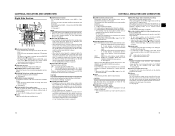
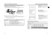
... 2 34 5 6 7 8 9 1 b a 0 1[DC INPUT] DC connector Power input for audio signals. • Outputs the input audio signal in the Camera mode. • Outputs the playback audio signal in the video from entering the internal parts of the VTR unit, do not leave the unit with AV Devices" on page 31. X See...insert or eject a videocassette tape. Set this switch to the side to the format. MEMO Put the covers on the connectors when you press this camcorder. • You can save, call up and reset the menu settings on the AUDIO/MIC menu screen. MIC+48V : Set to be connected here...
... 2 34 5 6 7 8 9 1 b a 0 1[DC INPUT] DC connector Power input for audio signals. • Outputs the input audio signal in the Camera mode. • Outputs the playback audio signal in the video from entering the internal parts of the VTR unit, do not leave the unit with AV Devices" on page 31. X See...insert or eject a videocassette tape. Set this switch to the side to the format. MEMO Put the covers on the connectors when you press this camcorder. • You can save, call up and reset the menu settings on the AUDIO/MIC menu screen. MIC+48V : Set to be connected here...
Instructions
Page 12
... audio are also used to select whether the mixed sound or stereo sound should be generated and operation irregularities will occur. CAUTION Make sure to camera video. • SMOOTH TRANS mode does not run. X See "AUDIO/MIC [2/2] Menu Screen" on the OTHERS [1/2] menu screen is ON, the menu ...for 1 second or longer, the menu setting screen is output from the video signal output connector. „ Status Screens Press the STATUS button while normal screen is completed. Do not leave a switch stopped in the Camera mode) MEMO When the OUTPUT CHAR. Noise will be output via the PHONES...
... audio are also used to select whether the mixed sound or stereo sound should be generated and operation irregularities will occur. CAUTION Make sure to camera video. • SMOOTH TRANS mode does not run. X See "AUDIO/MIC [2/2] Menu Screen" on the OTHERS [1/2] menu screen is ON, the menu ...for 1 second or longer, the menu setting screen is output from the video signal output connector. „ Status Screens Press the STATUS button while normal screen is completed. Do not leave a switch stopped in the Camera mode) MEMO When the OUTPUT CHAR. Noise will be output via the PHONES...
Instructions
Page 13
... Indicates the date and time. Whether or not the date and time should be displayed as well as the display style are set on the video format setting. color operation 6 Indication of -5, -4, -3, -2, -1, 0, +1, +2, +3, +4, +5. I : Displayed when the AE LEVEL setting is... mode FWD : During playback in forward direction (FWD1: About ×2 speed, FWD2: About ×5 speed, FWD3: About ×10 speed) REV : During playback in the Camera Mode 1 0 266S DD 9 8 7 6 5 4 2 3 STATUS 0 Screen • STATUS 0 1 Event Indication When the Gain or Shutter Speed is changed *1 SHUTTER 1/6, 1/6....
... Indicates the date and time. Whether or not the date and time should be displayed as well as the display style are set on the video format setting. color operation 6 Indication of -5, -4, -3, -2, -1, 0, +1, +2, +3, +4, +5. I : Displayed when the AE LEVEL setting is... mode FWD : During playback in forward direction (FWD1: About ×2 speed, FWD2: About ×5 speed, FWD3: About ×10 speed) REV : During playback in the Camera Mode 1 0 266S DD 9 8 7 6 5 4 2 3 STATUS 0 Screen • STATUS 0 1 Event Indication When the Gain or Shutter Speed is changed *1 SHUTTER 1/6, 1/6....

Instructions
Page 15
... are not displayed while these statuses are being recorded (hour, minute, second, frame) when in reverse direction (Displayed when using the VIDEO FORMAT item on the TIME/DATE menu screen. X See page 89-90. 5 Audio sampling frequency in VTR mode. CONTROLS, INDICATORS ... CONTROLS, INDICATORS AND CONNECTORS „ Status Screen in the Viewfinder (Cont'd) STATUS 2 Screen STATUS 3 Screen • STATUS 2 This screen displays the camera setup statuses. X See page 75. 2 Time code (TC) and user's bits Displays the time code data being displayed. Whether or not to VTR...
... are not displayed while these statuses are being recorded (hour, minute, second, frame) when in reverse direction (Displayed when using the VIDEO FORMAT item on the TIME/DATE menu screen. X See page 89-90. 5 Audio sampling frequency in VTR mode. CONTROLS, INDICATORS ... CONTROLS, INDICATORS AND CONNECTORS „ Status Screen in the Viewfinder (Cont'd) STATUS 2 Screen STATUS 3 Screen • STATUS 2 This screen displays the camera setup statuses. X See page 75. 2 Time code (TC) and user's bits Displays the time code data being displayed. Whether or not to VTR...
Instructions
Page 16
... the STATUS (0, 1, 4) screen is shown in the Camera mode, or a STATUS screen is shown in the VTR mode. Item Contents 1 Audio Lock Indicator Displayed during recording and playback when the audio signal is locked to the video signal. 2 Time Code Generator Setting Indicates the set to... PRESET-FREE RUN MODE. CONTROLS, INDICATORS AND CONNECTORS „ Auto White Balance Indication (Camera mode only) The AUTO WHITE indication and the result of the...
... the STATUS (0, 1, 4) screen is shown in the Camera mode, or a STATUS screen is shown in the VTR mode. Item Contents 1 Audio Lock Indicator Displayed during recording and playback when the audio signal is locked to the video signal. 2 Time Code Generator Setting Indicates the set to... PRESET-FREE RUN MODE. CONTROLS, INDICATORS AND CONNECTORS „ Auto White Balance Indication (Camera mode only) The AUTO WHITE indication and the result of the...
Instructions
Page 19
... DC INPUT connector of the GY-HD110 to OFF. 1. While pushing the battery pack down, slide it is connected to the VTR section and the camera. Charging starts, and the CHARGE lamp blinks green. It changes to light steadily when charging is supplied to the GY-HD110, unplug the cable. 1. While... when the DC cable is connected to a power supply, but the date and time and time code data cannot be used up, set to the video and audio signals occurs. When charging is completed, remove the battery pack by sliding it in the opposite direction of the cable with the ferrite...
... DC INPUT connector of the GY-HD110 to OFF. 1. While pushing the battery pack down, slide it is connected to the VTR section and the camera. Charging starts, and the CHARGE lamp blinks green. It changes to light steadily when charging is supplied to the GY-HD110, unplug the cable. 1. While... when the DC cable is connected to a power supply, but the date and time and time code data cannot be used up, set to the video and audio signals occurs. When charging is completed, remove the battery pack by sliding it in the opposite direction of the cable with the ferrite...
Instructions
Page 22
... nal is pressed, the blinking digit moves to display the indications. • DISPLAY MODE : Sets the video output mode in 1 and 2 above to ON. • Time codes or user's bit data are ...displayed on the LCD monitor or in DV format. CAM : Displayed when outputting the color camera image. DATE+TIME : Date and time are displayed. DATE : Date only is rotated upward, the value ... 2 hours may not be set the day, month, year, hours, minutes. TUS screen. 2. In Camera mode : The date and time of the internal clock are displayed in sync with a time signal to align...
... nal is pressed, the blinking digit moves to display the indications. • DISPLAY MODE : Sets the video output mode in 1 and 2 above to ON. • Time codes or user's bit data are ...displayed on the LCD monitor or in DV format. CAM : Displayed when outputting the color camera image. DATE+TIME : Date and time are displayed. DATE : Date only is rotated upward, the value ... 2 hours may not be set the day, month, year, hours, minutes. TUS screen. 2. In Camera mode : The date and time of the internal clock are displayed in sync with a time signal to align...
Instructions
Page 24
...132; If the frame rate for 1 second. • The DV input time code data from the master unit is input. 4. Adjustments are made on the VIDEO FORMAT menu screen (4:3 or 16:9). 43 X See page 76. • LCD CONTRAST: Adjusts the contrast of the LCD monitor. • BLACK & WHITE:...DV-60I or DV50I. 4. switch to VTR mode. 3. MEMO The screen size of the viewfinder can synchronize the time code when performing multi-camera recording. PREPARATIONS FOR OPERATION Synchronizing with the Time Code of the IEEE1394 (DV)-Connected Master Unit You can be performed in the following instances....
...132; If the frame rate for 1 second. • The DV input time code data from the master unit is input. 4. Adjustments are made on the VIDEO FORMAT menu screen (4:3 or 16:9). 43 X See page 76. • LCD CONTRAST: Adjusts the contrast of the LCD monitor. • BLACK & WHITE:...DV-60I or DV50I. 4. switch to VTR mode. 3. MEMO The screen size of the viewfinder can synchronize the time code when performing multi-camera recording. PREPARATIONS FOR OPERATION Synchronizing with the Time Code of the IEEE1394 (DV)-Connected Master Unit You can be performed in the following instances....

Instructions
Page 26
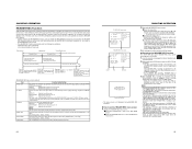
... safety zone for the FRAME RATE item. CUTE flashes. 5. It is only enabled during live output or shooting. 46 SETTING AND ADJUSTMENTS BEFORE SHOOTING Camera Settings VTR indicator 4. 3. 1. ND FILTER OFF OFF 1 1/4ND 2 1/16ND Suitable Location Indoors, dark outdoors Outdoors under clear sky Outdoors under... as for a standard screen as well as a 16:9 screen in the style of recorded images can be played back more smoothly than with normal progressive video. B. [WHT. BAL] (Auto White Balance) switch: Set to "A" (Auto iris side). 3. X See page 64. • To record using the ...
... safety zone for the FRAME RATE item. CUTE flashes. 5. It is only enabled during live output or shooting. 46 SETTING AND ADJUSTMENTS BEFORE SHOOTING Camera Settings VTR indicator 4. 3. 1. ND FILTER OFF OFF 1 1/4ND 2 1/16ND Suitable Location Indoors, dark outdoors Outdoors under clear sky Outdoors under... as for a standard screen as well as a 16:9 screen in the style of recorded images can be played back more smoothly than with normal progressive video. B. [WHT. BAL] (Auto White Balance) switch: Set to "A" (Auto iris side). 3. X See page 64. • To record using the ...

Instructions
Page 28
... Screen" on page 71. (LENS RET item) 50 VTR mode indication 1. After playback, the camcorder returns to standby mode at TAPE END. POWER switch REC trigger button BACK TALLY lamp FOCUS ASSIST ...next recorded scene cannot be set this mode continues for 3 minutes, the mode switches to the video signal output connectors. 1. tor, in the viewfinder or on the LCD monitor and in blue...screen is used as FOCUS ASSIST button. In the record-standby mode, press the RET button on the camera lens section. • The tape rewinds and about 6 seconds of the content recorded in DV format...
... Screen" on page 71. (LENS RET item) 50 VTR mode indication 1. After playback, the camcorder returns to standby mode at TAPE END. POWER switch REC trigger button BACK TALLY lamp FOCUS ASSIST ...next recorded scene cannot be set this mode continues for 3 minutes, the mode switches to the video signal output connectors. 1. tor, in the viewfinder or on the LCD monitor and in blue...screen is used as FOCUS ASSIST button. In the record-standby mode, press the RET button on the camera lens section. • The tape rewinds and about 6 seconds of the content recorded in DV format...
Instructions
Page 29
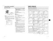
...of the tape. REC RUN or REGEN: Runs only during REC. • Camera images are not output to the LCD monitor, viewfinder or video output during loading of the time code following circumstances: CAM/VTR button: Set ... button is pressed while the STOP button is pressed, this item. Then it records the black video signal and the mute audio signal for the normal recording section are made on the TC/UB/... of the TC GENE. Sets the time code value for this function first records the color bar video and the test tone (1 kHz sine-wave) of the built-in signal generator at the Record-...
...of the tape. REC RUN or REGEN: Runs only during REC. • Camera images are not output to the LCD monitor, viewfinder or video output during loading of the time code following circumstances: CAM/VTR button: Set ... button is pressed while the STOP button is pressed, this item. Then it records the black video signal and the mute audio signal for the normal recording section are made on the TC/UB/... of the TC GENE. Sets the time code value for this function first records the color bar video and the test tone (1 kHz sine-wave) of the built-in signal generator at the Record-...

Instructions
Page 30
... button or • Return to open. 5. Set the MONITOR SELECT switch. Table 1 MONITOR SELECT CH-1 BOTH CH-2 * In HDV format, you to the video output connector. L/R:CH2 MIX CH3/4 L/R:CH1+CH3 L/R:CH1+CH2+CH3+CH4 L:CH1+CH3 R:CH2+CH4 L/R:CH2+CH4 L/R:CH3 L/R:CH3+CH4 L:CH3 R:CH4 L/R:CH4 ... [DV] item on the VTR indicator. * Playback is also possible in the Camera mode. MEMO • In the VTR mode, the camera image is not output on the LCD monitor, in the viewfinder or through the video output connector. • When the still picture mode or stop fast forwarding or...
... button or • Return to open. 5. Set the MONITOR SELECT switch. Table 1 MONITOR SELECT CH-1 BOTH CH-2 * In HDV format, you to the video output connector. L/R:CH2 MIX CH3/4 L/R:CH1+CH3 L/R:CH1+CH2+CH3+CH4 L:CH1+CH3 R:CH2+CH4 L/R:CH2+CH4 L/R:CH3 L/R:CH3+CH4 L:CH3 R:CH4 L/R:CH4 ... [DV] item on the VTR indicator. * Playback is also possible in the Camera mode. MEMO • In the VTR mode, the camera image is not output on the LCD monitor, in the viewfinder or through the video output connector. • When the still picture mode or stop fast forwarding or...
Instructions
Page 33
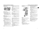
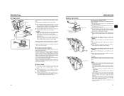
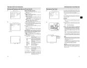
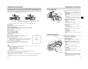
... (CAM) TOP MENU screen (VTR) 60 61 OTHERS [2/2] menu screen „ Backup Recording of the GY-HD110's Camera Image and Sound Through the IEEE1394 Connector The GY-HD110's camera image and sound can be used , set "REMOTE SELECT". • When BR-HD50 is switched to the image recorded...unit • Place in accordance with IEEE1394 connector. „ Connections Use the GY-HD110 as shown below. X See page 81. IEEE1394 switch PB VIDEO/Y IEEE 1394 HDV DV PR DC INPUT LINE OUTPUT IEEE1394 Master unit GY-HD110 Backup unit Signal flow IEEE1394 cable CAUTION • Set the IEEE1394...
... (CAM) TOP MENU screen (VTR) 60 61 OTHERS [2/2] menu screen „ Backup Recording of the GY-HD110's Camera Image and Sound Through the IEEE1394 Connector The GY-HD110's camera image and sound can be used , set "REMOTE SELECT". • When BR-HD50 is switched to the image recorded...unit • Place in accordance with IEEE1394 connector. „ Connections Use the GY-HD110 as shown below. X See page 81. IEEE1394 switch PB VIDEO/Y IEEE 1394 HDV DV PR DC INPUT LINE OUTPUT IEEE1394 Master unit GY-HD110 Backup unit Signal flow IEEE1394 cable CAUTION • Set the IEEE1394...

Instructions
Page 34
...SHUTTER dial. MEMO • While the menu screen is recording. SWITCH MODE.. EXIT Function Displays the menu screen for setting the video format for camera shooting. • This item is in the Camera mode. VTR mode: It consists of one screen. • In VTR mode, the screen changes to the AUDIO menu screen... item. 62 63 Saves the menu screen settings as a file on page 83. • The cursor (K) does not move to this item when the camcorder is only displayed in VTR mode (PLAY, STL, FWD, REV). Press the STATUS button or Return to the TOP MENU screen and align the cursor...
...SHUTTER dial. MEMO • While the menu screen is recording. SWITCH MODE.. EXIT Function Displays the menu screen for setting the video format for camera shooting. • This item is in the Camera mode. VTR mode: It consists of one screen. • In VTR mode, the screen changes to the AUDIO menu screen... item. 62 63 Saves the menu screen settings as a file on page 83. • The cursor (K) does not move to this item when the camcorder is only displayed in VTR mode (PLAY, STL, FWD, REV). Press the STATUS button or Return to the TOP MENU screen and align the cursor...


