Instruction Manual
Page 1
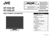
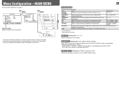
... cover (or back). Refer servicing to constitute a risk of important operating and maintenance (servicing) instructions in the literature accompanying the appliance. DT-V24L3D DT-V20L3D MULTI FORMAT LCD MONITOR The illustration of the monitor is of Contents Safety Precautions 2 IMPORTANT SAFEGUARDS 2 Installation 4 Daily Operations / Connections 6 Front panel 6 Rear panel 8 Available signals 9 Menu Configuration-MAIN MENU...
... cover (or back). Refer servicing to constitute a risk of important operating and maintenance (servicing) instructions in the literature accompanying the appliance. DT-V24L3D DT-V20L3D MULTI FORMAT LCD MONITOR The illustration of the monitor is of Contents Safety Precautions 2 IMPORTANT SAFEGUARDS 2 Installation 4 Daily Operations / Connections 6 Front panel 6 Rear panel 8 Available signals 9 Menu Configuration-MAIN MENU...
Instruction Manual
Page 4
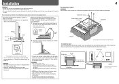
...176;), the guidelines align as illustrated below . CAUTION • Be careful not to about 148°. The illustrations of the monitor are of DT-V24L3D. • To place the monitor as illustrated below. 1 Remove the screws on the left and right sides of lifting the stand up until it on a cloth... with the LCD panel facing down to the lower position of DT-V24L3D. CAUTION • When lifting up by about 6° downward. • When the monitor is of the stand body, you can tilt the monitor from about 6° upward to pinch your fingers ...
...176;), the guidelines align as illustrated below . CAUTION • Be careful not to about 148°. The illustrations of the monitor are of DT-V24L3D. • To place the monitor as illustrated below. 1 Remove the screws on the left and right sides of lifting the stand up until it on a cloth... with the LCD panel facing down to the lower position of DT-V24L3D. CAUTION • When lifting up by about 6° downward. • When the monitor is of the stand body, you can tilt the monitor from about 6° upward to pinch your fingers ...
Instruction Manual
Page 5
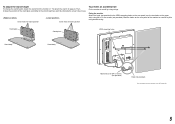
...mounting holes Stand body Stand body Hook and screw (M4 x 10 mm) (not provided) Hook (not provided) The illustration of the monitor is of DT-V24L3D. 5 Fixing the monitor Attach the hook (not provided) to the VESA mounting holes on the rear panel (use . Then, change the stand height, detach the... stand from the monitor (☞ "To detach the stand" on the upper side) using durable string. Screw holes for higher position Screw ...
...mounting holes Stand body Stand body Hook and screw (M4 x 10 mm) (not provided) Hook (not provided) The illustration of the monitor is of DT-V24L3D. 5 Fixing the monitor Attach the hook (not provided) to the VESA mounting holes on the rear panel (use . Then, change the stand height, detach the... stand from the monitor (☞ "To detach the stand" on the upper side) using durable string. Screw holes for higher position Screw ...
Instruction Manual
Page 6
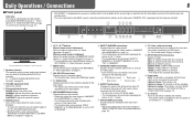
...r T.C. (time code) button/lamp Activates/deactivates the display of the time data (time code) contained in "WAVE FORM SETTING" of the wave form monitor in the SDI signal. (☞ "On the Information Display" on page 7) t INPUT SELECT buttons/lamps Selects an input. u button Turns on and ... 2) terminal DVI: DVI-D (HDCP) terminal COMPO./RGB: COMPO./RGB. Lights in Green: The monitor is turned off (on standby). Lights in orange: The monitor is in the P. The illustration of the monitor is of DT-V24L3D. 1 Speakers (stereo) The speakers emit the same audio signal emitted from 4:3 to 16...
...r T.C. (time code) button/lamp Activates/deactivates the display of the time data (time code) contained in "WAVE FORM SETTING" of the wave form monitor in the SDI signal. (☞ "On the Information Display" on page 7) t INPUT SELECT buttons/lamps Selects an input. u button Turns on and ... 2) terminal DVI: DVI-D (HDCP) terminal COMPO./RGB: COMPO./RGB. Lights in Green: The monitor is turned off (on standby). Lights in orange: The monitor is in the P. The illustration of the monitor is of DT-V24L3D. 1 Speakers (stereo) The speakers emit the same audio signal emitted from 4:3 to 16...
Instruction Manual
Page 7
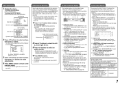
...• For the contents displayed, see "On the signal format" below is also displayed in from the speakers (L/R) and the AUDIO ASSIGN (MONITOR OUT) (OUT1(L)/OUT2(R)) terminals, when EMBEDDED AUDIO signals come in the following messages appear depending on the type of the current input changes -...page 14). Ex.: When "MARKER" in "AUDIO SETTING" on page 6 On the signal format The following cases: - On the Information Display The monitor displays the information below. • Make the setting to display/hide each input (SDI 1 and SDI 2). On the Status Display If you change the...
...• For the contents displayed, see "On the signal format" below is also displayed in from the speakers (L/R) and the AUDIO ASSIGN (MONITOR OUT) (OUT1(L)/OUT2(R)) terminals, when EMBEDDED AUDIO signals come in the following messages appear depending on the type of the current input changes -...page 14). Ex.: When "MARKER" in "AUDIO SETTING" on page 6 On the signal format The following cases: - On the Information Display The monitor displays the information below. • Make the setting to display/hide each input (SDI 1 and SDI 2). On the Status Display If you change the...
Instruction Manual
Page 8
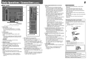
...IN 1/IN 2) terminals (pin jack) Input terminals for the analog audio signals. • Use this terminal only when the monitor is not displayed correctly, change the setting of DT-V24L3D. 1 Power switch Turns the power on or off all other than SDI 1 and SDI 2 is selected, the ... input (SDI 1 or SDI 2) are re-clocked, then emitted. • When an input other connections are completed. 3 REMOTE terminal Terminal for controlling the monitor by an external control. (☞ "External Control" on the right). Daily Operations / Connections (cont.) 8 7 Rear panel 1 2 Security slot Attach a ...
...IN 1/IN 2) terminals (pin jack) Input terminals for the analog audio signals. • Use this terminal only when the monitor is not displayed correctly, change the setting of DT-V24L3D. 1 Power switch Turns the power on or off all other than SDI 1 and SDI 2 is selected, the ... input (SDI 1 or SDI 2) are re-clocked, then emitted. • When an input other connections are completed. 3 REMOTE terminal Terminal for controlling the monitor by an external control. (☞ "External Control" on the right). Daily Operations / Connections (cont.) 8 7 Rear panel 1 2 Security slot Attach a ...
Instruction Manual
Page 9
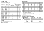
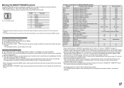
...√ √ DVI-D (HDCP) (Digital component/ digital RGB) 3 √: Acceptable -: Not acceptable *1 Analog component/analog RGB signals are available for this monitor. Video signals No. Signal name Resolution Horizontal Vertical 1 VGA60 640 480 2 WVGA60 852 480 3 SVGA60 800 600 4 XGA60 1024 768 5 WXGA (1280) 1280 ...-interlace Non-interlace Non-interlace Non-interlace Non-interlace Non-interlace Non-interlace Non-interlace Non-interlace Non-interlace *4 For DT-V20L3D: When No. 9, 10, 12 or 14 signals come in, thin lines will become obscured because their signal ...
...√ √ DVI-D (HDCP) (Digital component/ digital RGB) 3 √: Acceptable -: Not acceptable *1 Analog component/analog RGB signals are available for this monitor. Video signals No. Signal name Resolution Horizontal Vertical 1 VGA60 640 480 2 WVGA60 852 480 3 SVGA60 800 600 4 XGA60 1024 768 5 WXGA (1280) 1280 ...-interlace Non-interlace Non-interlace Non-interlace Non-interlace Non-interlace Non-interlace Non-interlace Non-interlace Non-interlace *4 For DT-V20L3D: When No. 9, 10, 12 or 14 signals come in, thin lines will become obscured because their signal ...
Instruction Manual
Page 10
...the input picture. reset Restore the default settings for all the items in "PICTURE FUNCTION." *1 DT-V24L3D only *2 Memorized for COMPO./RGB terminals. COMPO./RGB SEL. OFF, ON APERTURE FREQ.*2... for each input. OFF, NORMAL, HARD LTI Adjust the clearness of the outlines of the monitor is not displayed correctly with "AUTO." • DVI-D input of the luminance signal. DVI... picture quality Item To do Setting value MOVING PICTURE*1 Reduce the lag of signals come in to LCD. NORMAL, CINEMA, FIELD sub menu Display the sub menu which is peculiar to the DVI-D (...
...the input picture. reset Restore the default settings for all the items in "PICTURE FUNCTION." *1 DT-V24L3D only *2 Memorized for COMPO./RGB terminals. COMPO./RGB SEL. OFF, ON APERTURE FREQ.*2... for each input. OFF, NORMAL, HARD LTI Adjust the clearness of the outlines of the monitor is not displayed correctly with "AUTO." • DVI-D input of the luminance signal. DVI... picture quality Item To do Setting value MOVING PICTURE*1 Reduce the lag of signals come in to LCD. NORMAL, CINEMA, FIELD sub menu Display the sub menu which is peculiar to the DVI-D (...

Instruction Manual
Page 13
... sync) ON, OFF • When setting "NO SYNC ACTION" to "GRAY B.," the screen color changes to make the ON, OFF wave form monitor indication go off the back light. *2 Memorized for the incoming luminance ☞ "NOTE" signals. LEVEL Adjust the lower limit for the luminance signal ...070 -109 AUTO OFF Activates/deactivates the function to gray and the power consumption of the wave form monitor. 1 (lower right), 2 (lower left), 3 (upper left), 4 (upper right) FILTER Activates/deactivates the low-pass filter for the synchronization with...
... sync) ON, OFF • When setting "NO SYNC ACTION" to "GRAY B.," the screen color changes to make the ON, OFF wave form monitor indication go off the back light. *2 Memorized for the incoming luminance ☞ "NOTE" signals. LEVEL Adjust the lower limit for the luminance signal ...070 -109 AUTO OFF Activates/deactivates the function to gray and the power consumption of the wave form monitor. 1 (lower right), 2 (lower left), 3 (upper left), 4 (upper right) FILTER Activates/deactivates the low-pass filter for the synchronization with...
Instruction Manual
Page 14
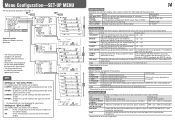
...6500K, USER MIN - 000 - while viewing the actual picture. UPPER1: Displays the current setting and adjustment bar at the lower part of the monitor display. OFF: Fit the vertical picture size into that of the tally lamp and the picture size. SIZE/POSI. Restore the default settings for ...on the front panel. MIN - 000 - MAX (in "PICTURE SUB ADJ." *1 Memorized for the sub menu display, color system, color of the monitor display. 14 FUNCTION SETTING Setting for each signal format. Adjusts the standard level for the input video signal. Select the set-up level of the...
...6500K, USER MIN - 000 - while viewing the actual picture. UPPER1: Displays the current setting and adjustment bar at the lower part of the monitor display. OFF: Fit the vertical picture size into that of the tally lamp and the picture size. SIZE/POSI. Restore the default settings for ...on the front panel. MIN - 000 - MAX (in "PICTURE SUB ADJ." *1 Memorized for the sub menu display, color system, color of the monitor display. 14 FUNCTION SETTING Setting for each signal format. Adjusts the standard level for the input video signal. Select the set-up level of the...
Instruction Manual
Page 15
...the name assigned in "PARALLEL TYPE." (The functions are memorized. 5 Repeat steps 3 and 4 (10 characters at maximum). Display the hours of the monitor to the default. • "HOUR METER" and the settings done by selecting "SET" in "CHARACTER SET." appears on page 7). Space 4 Press button... on pages 16 to show the information display (☞ "On the Information Display" on page 17 INFORMATION Settings for maintenance of the monitor Item POSITION SOURCE ID CHARACTER SET.*1 STATUS DISPLAY CRC ERROR SUB HOUR METER MODEL VERSION HOUR METER To do not appear on automatically. ...
...the name assigned in "PARALLEL TYPE." (The functions are memorized. 5 Repeat steps 3 and 4 (10 characters at maximum). Display the hours of the monitor to the default. • "HOUR METER" and the settings done by selecting "SET" in "CHARACTER SET." appears on page 7). Space 4 Press button... on pages 16 to show the information display (☞ "On the Information Display" on page 17 INFORMATION Settings for maintenance of the monitor Item POSITION SOURCE ID CHARACTER SET.*1 STATUS DISPLAY CRC ERROR SUB HOUR METER MODEL VERSION HOUR METER To do not appear on automatically. ...

Instruction Manual
Page 16
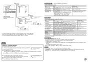
... TYPE" setting "PARALLEL TYPE" setting - PC, etc. RS-485 OUT RS-485 RS-485 IN OUT RS232C*1 - *1 For a monitor connected to a personal computer etc, select the terminal the equipment is actually connected to the external control terminal and control system (☞ "...SERIAL TYPE", "PARALLEL TYPE" on standby), external control is not available. External Control 16 7 About the external control This monitor has three external control terminals. • MAKE/TRIGGER terminal (RJ-45): The following external control systems are available through the serial communication...
... TYPE" setting "PARALLEL TYPE" setting - PC, etc. RS-485 OUT RS-485 RS-485 IN OUT RS232C*1 - *1 For a monitor connected to a personal computer etc, select the terminal the equipment is actually connected to the external control terminal and control system (☞ "...SERIAL TYPE", "PARALLEL TYPE" on standby), external control is not available. External Control 16 7 About the external control This monitor has three external control terminals. • MAKE/TRIGGER terminal (RJ-45): The following external control systems are available through the serial communication...
Instruction Manual
Page 17
... second and opening ) and blue screen (short-circuiting). When the "TRIGGER" system is selected: Operate each function by pulse control, that the monitor can be controlled by one function at the moment of short-circuiting. *5 While controlling with the TRIGGER system, the pattern of "REMOTE SETTING" ... ratio C.MARKER The center marker indication MARK.SEL Selects the items of the tally lamp. Controls whether displaying/hiding the wave form monitor (This function cannot be controlled with the MAKE system.). *7 While controlling with the MAKE system, the screen is short-circuiting the...
... second and opening ) and blue screen (short-circuiting). When the "TRIGGER" system is selected: Operate each function by pulse control, that the monitor can be controlled by one function at the moment of short-circuiting. *5 While controlling with the TRIGGER system, the pattern of "REMOTE SETTING" ... ratio C.MARKER The center marker indication MARK.SEL Selects the items of the tally lamp. Controls whether displaying/hiding the wave form monitor (This function cannot be controlled with the MAKE system.). *7 While controlling with the MAKE system, the screen is short-circuiting the...

Instruction Manual
Page 18
... communication: connection command (!00BCN1Cr) 2Monitor's status (@00BOKCr) PC, etc. 3Selecting "SDI 1" input (!00BINACr) 4Monitor's status (@00BOKCr) 5Terminating the communication: termination command (!00BCN0Cr) 6Monitor's status (@00BOKCr) Monitor No. Commands Functions 1 ! * **1 B C N 1 Cr Starts communication (connection) 2 ! * **1 B C N 0 Cr Terminates communication (termination) 3 ! * **1 B I D S E T x x*2 Cr...Code This is a female terminal. TXD - "@": Status returns from the monitor • To start communication, send the connection command from the personal computer ...
... communication: connection command (!00BCN1Cr) 2Monitor's status (@00BOKCr) PC, etc. 3Selecting "SDI 1" input (!00BINACr) 4Monitor's status (@00BOKCr) 5Terminating the communication: termination command (!00BCN0Cr) 6Monitor's status (@00BOKCr) Monitor No. Commands Functions 1 ! * **1 B C N 1 Cr Starts communication (connection) 2 ! * **1 B C N 0 Cr Terminates communication (termination) 3 ! * **1 B I D S E T x x*2 Cr...Code This is a female terminal. TXD - "@": Status returns from the monitor • To start communication, send the connection command from the personal computer ...
Instruction Manual
Page 19
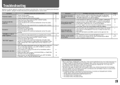
..." or "BRIGHT" of "WHITE BALANCE SET." ADJ." There is acceptable on the monitor. • Select the correct input using the adjustment knobs on the menu. The LCD display is acceptable on the front panel or adjust the items of "SIZE/POSI. If... items controlled by the MAKE system. Though the remaining picture will disappear after the picture has changed. The monitor emits a mechanical noise. 19 Troubleshooting Solutions to common problems related to the characteristics of LCD displays, and not a problem. Or, perform "reset" in the SET-UP MENU. Page 6 8 8 6 8 - 9 6 6 8 - ...
..." or "BRIGHT" of "WHITE BALANCE SET." ADJ." There is acceptable on the monitor. • Select the correct input using the adjustment knobs on the menu. The LCD display is acceptable on the front panel or adjust the items of "SIZE/POSI. If... items controlled by the MAKE system. Though the remaining picture will disappear after the picture has changed. The monitor emits a mechanical noise. 19 Troubleshooting Solutions to common problems related to the characteristics of LCD displays, and not a problem. Or, perform "reset" in the SET-UP MENU. Page 6 8 8 6 8 - 9 6 6 8 - ...
Instruction Manual
Page 20
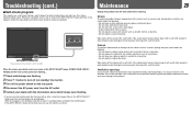
..., be careful about which lamps are flashing. 2 Press button to turn on the monitor soon after turning it with a soft cloth soaked in appearance of DT-V24L3D. Troubleshooting (cont.) 7 Self-check program This monitor has a self-check function, which allows it to detect malfunctions and alert you can..., VIDEO1, VIDEO2) on the front control panel start flashing... 1 Check which lamps were flashing. • If you turn off (on the monitor again. Ventilation openings Use a vacuum cleaner to get rid of the cabinet such as its paint's peeling away, be displayed. When this happens...
..., be careful about which lamps are flashing. 2 Press button to turn on the monitor soon after turning it with a soft cloth soaked in appearance of DT-V24L3D. Troubleshooting (cont.) 7 Self-check program This monitor has a self-check function, which allows it to detect malfunctions and alert you can..., VIDEO1, VIDEO2) on the front control panel start flashing... 1 Check which lamps were flashing. • If you turn off (on the monitor again. Ventilation openings Use a vacuum cleaner to get rid of the cabinet such as its paint's peeling away, be displayed. When this happens...
Instruction Manual
Page 21
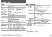
... and illustrations are shown by being emphasized, omitted or composed, and may be slightly different from sources other than JVC or JVC-authorized dealers. 7 Input/output terminals Model name DT-V24L3D DT-V20L3D VIDEO (INPUT 1) Input/output of composite sync signal: 1 line, BNC connector x 2, 0.3 V(p-p) -... format Format Audio output Operating conditions Power requirements Rated current External dimensions (excluding protruding parts) Weight Accessories DT-V24L3D DT-V20L3D Multi format LCD monitor Type 24 wide format Type 20 wide format 16:10 24˝ wide, active matrix TFT 20...
... and illustrations are shown by being emphasized, omitted or composed, and may be slightly different from sources other than JVC or JVC-authorized dealers. 7 Input/output terminals Model name DT-V24L3D DT-V20L3D VIDEO (INPUT 1) Input/output of composite sync signal: 1 line, BNC connector x 2, 0.3 V(p-p) -... format Format Audio output Operating conditions Power requirements Rated current External dimensions (excluding protruding parts) Weight Accessories DT-V24L3D DT-V20L3D Multi format LCD monitor Type 24 wide format Type 20 wide format 16:10 24˝ wide, active matrix TFT 20...
Instruction Manual
Page 24
DT-V24L3D/DT-V20L3D MULTI FORMAT LCD MONITOR © 2008 Victor Company of Japan, Limited 0908TKH-MW-MT
DT-V24L3D/DT-V20L3D MULTI FORMAT LCD MONITOR © 2008 Victor Company of Japan, Limited 0908TKH-MW-MT

