Owners Manual 3
Page 4
...) From Radio Wave Sources ...24 Powered Wheelchair Electromagnetic Interference (EMI) ...25 4 TECHNICAL DATA 26 Typical Product Parameters...26 Seat ...26 Weight ...28 5 USAGE 29 Preparing the Joystick for Use...29 A Note About Drive Lock-Out ...30 Operating Powered Seating Systems ...31 Using the Powered Seating Switch...32 Using the MK6i SPJ+... ...38 Installing/Removing Footrests...38 PH904A, PHAL4A, 70° and PW93...38 70° Taper ...39 Raising/Lowering Elevating Front Riggings ...39 Invacare® Adjustable ASBA Seats 4 Part No 1143192 Reaching, Leaning and Bending -
...) From Radio Wave Sources ...24 Powered Wheelchair Electromagnetic Interference (EMI) ...25 4 TECHNICAL DATA 26 Typical Product Parameters...26 Seat ...26 Weight ...28 5 USAGE 29 Preparing the Joystick for Use...29 A Note About Drive Lock-Out ...30 Operating Powered Seating Systems ...31 Using the Powered Seating Switch...32 Using the MK6i SPJ+... ...38 Installing/Removing Footrests...38 PH904A, PHAL4A, 70° and PW93...38 70° Taper ...39 Raising/Lowering Elevating Front Riggings ...39 Invacare® Adjustable ASBA Seats 4 Part No 1143192 Reaching, Leaning and Bending -
Owners Manual 3
Page 31
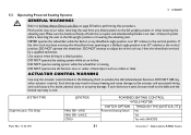
... w/ACC CMPJ+ POWERED SEATING CONTROL 4 POLE MOTOR SWITCH OPTION THROUGH THE JOYSTICK (TTJ) Powered Seating Switch No Yes Yes with SANODE Part No 1143192 31 Invacare® Adjustable ASBA Seats NEVER operate the wheelchair while the back is...elevating seat. 5 USAGE 5.3 Operating Powered Seating Systems ƽ GENERAL WARNINGS Refer to A Note About Drive Lock-Out on an incline. DO NOT attempt to the vertical position. ACTUATOR CONTROL WARNING Use only the actuator controls listed in a tilted position. Pinch points may result in any other actuator controls. Have the wheelchair...
... w/ACC CMPJ+ POWERED SEATING CONTROL 4 POLE MOTOR SWITCH OPTION THROUGH THE JOYSTICK (TTJ) Powered Seating Switch No Yes Yes with SANODE Part No 1143192 31 Invacare® Adjustable ASBA Seats NEVER operate the wheelchair while the back is...elevating seat. 5 USAGE 5.3 Operating Powered Seating Systems ƽ GENERAL WARNINGS Refer to A Note About Drive Lock-Out on an incline. DO NOT attempt to the vertical position. ACTUATOR CONTROL WARNING Use only the actuator controls listed in a tilted position. Pinch points may result in any other actuator controls. Have the wheelchair...
Owners Manual 3
Page 43
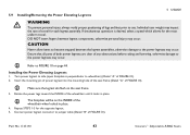
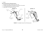
...to the power legrests may occur. Refer to wheelchair) (Detail "A" of FIGURE 10). 2. Insert the mounting pin of power legrest into the mounting hole of the seat frame (Detail "A" of FIGURE 10). Part No 1143192 43 Invacare® Adjustable ASBA Seats Turn power legrest ... otherwise personal injury may occur. Installing the Power Elevating Legrests 1. 5.9 Installing/Removing the Power Elevating Legrests 5 USAGE ƽ WARNING To prevent personal injury, always verify proper positioning of legs and feet prior to the power legrests may occur. If simultaneous operation is ...
...to the power legrests may occur. Refer to wheelchair) (Detail "A" of FIGURE 10). 2. Insert the mounting pin of power legrest into the mounting hole of the seat frame (Detail "A" of FIGURE 10). Part No 1143192 43 Invacare® Adjustable ASBA Seats Turn power legrest ... otherwise personal injury may occur. Installing the Power Elevating Legrests 1. 5.9 Installing/Removing the Power Elevating Legrests 5 USAGE ƽ WARNING To prevent personal injury, always verify proper positioning of legs and feet prior to the power legrests may occur. If simultaneous operation is ...
Owners Manual 3
Page 44
Repeat STEPS 1-3 for opposite power legrest. Mounting Hole DETAIL "A" Mounting Pin Calf Pad DETAIL "B" Legrest Release Handle Footplate Jumper Cable Power Legrest Connector FIGURE 10 Installing/Removing the Power Elevating Legrests Invacare® Adjustable ASBA Seats 44 Part No 1143192 Push legrest release handle and swing legrest to the outside of the wheelchair. 3. Lift up on powered legrest and remove from jumper cable. 2. Disconnect power legrest connector from wheelchair. 4. 5 USAGE Removing the Power Elevating Legrests 1.
Repeat STEPS 1-3 for opposite power legrest. Mounting Hole DETAIL "A" Mounting Pin Calf Pad DETAIL "B" Legrest Release Handle Footplate Jumper Cable Power Legrest Connector FIGURE 10 Installing/Removing the Power Elevating Legrests Invacare® Adjustable ASBA Seats 44 Part No 1143192 Push legrest release handle and swing legrest to the outside of the wheelchair. 3. Lift up on powered legrest and remove from jumper cable. 2. Disconnect power legrest connector from wheelchair. 4. 5 USAGE Removing the Power Elevating Legrests 1.

Owners Manual 4
Page 11
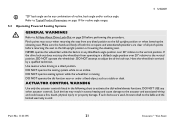
...be replaced immediately. Doing so may cause your wheelchair. Before adjusting, repairing or servicing the wheelchair, ALWAYS turn over curbs or obstacles. DO NOT leave the power button On when entering or exiting your wheelchair to turn the wheelchair power Off, otherwise, injury or damage may require ...wheelchair unattended on an incline. DO NOT leave elevating legrests in the fully extended position when proceeding down ramps or slopes at half speed or slower and to drive over and cause bodily harm or damage to the wheelchair. Part No 1143195 11 Invacare® Van Seat...
...be replaced immediately. Doing so may cause your wheelchair. Before adjusting, repairing or servicing the wheelchair, ALWAYS turn over curbs or obstacles. DO NOT leave the power button On when entering or exiting your wheelchair to turn the wheelchair power Off, otherwise, injury or damage may require ...wheelchair unattended on an incline. DO NOT leave elevating legrests in the fully extended position when proceeding down ramps or slopes at half speed or slower and to drive over and cause bodily harm or damage to the wheelchair. Part No 1143195 11 Invacare® Van Seat...
Owners Manual 4
Page 21
... elevating seat. ACTUATOR CONTROL WARNING Use only the actuator controls listed in a tilted position. Refer to Typical Product Parameters on page 19 for recline angle ranges. 5.2 Operating Powered Seating Systems ƽ GENERAL WARNINGS Refer to the vertical position, DO NOT operate the wheelchair.... full upright position or when lowering the elevating seat. DO NOT operate seating system while the wheelchair is in excess heating and cause damage to the vertical position. Part No 1143195 21 Invacare® Van Seat Have the wheelchair serviced by a qualified technician. DO NOT...
... elevating seat. ACTUATOR CONTROL WARNING Use only the actuator controls listed in a tilted position. Refer to Typical Product Parameters on page 19 for recline angle ranges. 5.2 Operating Powered Seating Systems ƽ GENERAL WARNINGS Refer to the vertical position, DO NOT operate the wheelchair.... full upright position or when lowering the elevating seat. DO NOT operate seating system while the wheelchair is in excess heating and cause damage to the vertical position. Part No 1143195 21 Invacare® Van Seat Have the wheelchair serviced by a qualified technician. DO NOT...

Owners Manual 4
Page 22
5 USAGE SYSTEM TYPE Single Actuator (Elevate Only) JOYSTICK MK6i SPJ+ w/PSS MK6i SPJ+ w/ACC CMPJ+ POWERED SEATING CONTROL 4 POLE MOTOR SWITCH OPTION THROUGH THE JOYSTICK (TTJ) Powered Seating Switch No Yes Yes with SANODE This procedure only applies to tilt mode. Invacare® Van Seat 22 Part No 1143195 Make sure the wheelchair is on a level surface. 2. Make...
5 USAGE SYSTEM TYPE Single Actuator (Elevate Only) JOYSTICK MK6i SPJ+ w/PSS MK6i SPJ+ w/ACC CMPJ+ POWERED SEATING CONTROL 4 POLE MOTOR SWITCH OPTION THROUGH THE JOYSTICK (TTJ) Powered Seating Switch No Yes Yes with SANODE This procedure only applies to tilt mode. Invacare® Van Seat 22 Part No 1143195 Make sure the wheelchair is on a level surface. 2. Make...
Owners Manual 4
Page 24
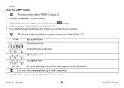
...icons indicate up/down, up or down, respectively. 5. ICON DESCRIPTION Elevate Operations Combined Power Leg Operations Right Leg Operations Left Leg Operations No Icons No powered seating operation has been programmed for this procedure, refer to FIGURE 2 on a level surface. 2. Make sure the wheelchair is selected: The location of the icons indicates the .... Four of the following icons will display when Actuator Control Switch Mode is on page 25. 1. Select the Actuator Control Switch Mode icon (Detail "A"). 4. Invacare® Van Seat 24 Part No 1143195
...icons indicate up/down, up or down, respectively. 5. ICON DESCRIPTION Elevate Operations Combined Power Leg Operations Right Leg Operations Left Leg Operations No Icons No powered seating operation has been programmed for this procedure, refer to FIGURE 2 on a level surface. 2. Make sure the wheelchair is selected: The location of the icons indicates the .... Four of the following icons will display when Actuator Control Switch Mode is on page 25. 1. Select the Actuator Control Switch Mode icon (Detail "A"). 4. Invacare® Van Seat 24 Part No 1143195

Owners Manual
Page 38
...two 22NF Batteries: Without GP24 Batteries: With Two GP24 Batteries: With Transport Ready Option: *Maximum Weight Limitations With ASBA Seat: With ASBA Jr. Seat: With Van Seat: With Formula CG Powered Seating: With Elevating ASBA Seat: TDX SP TDX SR TDX SR HD Telescoping Front Rigging Supports, 2 in and 4 in long Pivot Slide Tube...Up to 400 lbs Up to 400 lbs N/A *Weight limitation is 275 lbs. Invacare® TDX®SP, TDX SR 38 Part No 1143190 Example: If weight limitation of the wheelchair is 300 lbs and additional items equal 25 lbs, subtract 25 lbs from 300 lbs this means...
...two 22NF Batteries: Without GP24 Batteries: With Two GP24 Batteries: With Transport Ready Option: *Maximum Weight Limitations With ASBA Seat: With ASBA Jr. Seat: With Van Seat: With Formula CG Powered Seating: With Elevating ASBA Seat: TDX SP TDX SR TDX SR HD Telescoping Front Rigging Supports, 2 in and 4 in long Pivot Slide Tube...Up to 400 lbs Up to 400 lbs N/A *Weight limitation is 275 lbs. Invacare® TDX®SP, TDX SR 38 Part No 1143190 Example: If weight limitation of the wheelchair is 300 lbs and additional items equal 25 lbs, subtract 25 lbs from 300 lbs this means...


