
Product Guide
Page 5
......24 8. Connect the Processor Fan 25 10. Installing a VRM ...28 13. Configuration Utilities 31 5. Processor Clock Speed Jumper 26 11. Hot Keys ...31 6. Power Usage Worksheet 1 74 9. Server Board Connector and Component Locations 9 3. Problems with Application Software 64... Bootable CD-ROM Is Not Detected 64 5 Technical Reference Server Board Jumpers...65 6 Regulatory and Integration Information Product Regulatory Compliance 67...
......24 8. Connect the Processor Fan 25 10. Installing a VRM ...28 13. Configuration Utilities 31 5. Processor Clock Speed Jumper 26 11. Hot Keys ...31 6. Power Usage Worksheet 1 74 9. Server Board Connector and Component Locations 9 3. Problems with Application Software 64... Bootable CD-ROM Is Not Detected 64 5 Technical Reference Server Board Jumpers...65 6 Regulatory and Integration Information Product Regulatory Compliance 67...

Product Guide
Page 9
... FAN1 (P11) Z. Main power connector (P33) N. System fan connector FAN2A (P27) B. VRM socket (P32) O. Primary processor (P13) E. IDE connector (P19) J. Primary processor heatsink fan connector (P12) Figure 2. Server Board Connector and Component Locations Description 9 Floppy drive connector (P20) K. Chassis intrusion connector (pins 1-2...bit PCI connectors W. 66 MHz/64-bit PCI connectors X. Ultra160 LVD SCSI connector (P8) S. Battery T. Server Board Connector and Component Locations A B C D EF G H AA I Z J K L Y M NO X P Q W V R U TS OM10670 A.
... FAN1 (P11) Z. Main power connector (P33) N. System fan connector FAN2A (P27) B. VRM socket (P32) O. Primary processor (P13) E. IDE connector (P19) J. Primary processor heatsink fan connector (P12) Figure 2. Server Board Connector and Component Locations Description 9 Floppy drive connector (P20) K. Chassis intrusion connector (pins 1-2...bit PCI connectors W. 66 MHz/64-bit PCI connectors X. Ultra160 LVD SCSI connector (P8) S. Battery T. Server Board Connector and Component Locations A B C D EF G H AA I Z J K L Y M NO X P Q W V R U TS OM10670 A.

Product Guide
Page 28
.... Eksplosionsfare ved fejlagtig håndtering. Brukt batteri returneres apparatleverandøren. 28 Intel Server Board STL2 Product Guide Replace only with the same or equivalent type recommended by the equipment manufacturer. Orient the VRM as shown and press it loses voltage, and the server settings stored in CMOS RAM in the RTC (for up to manufacturer...
.... Eksplosionsfare ved fejlagtig håndtering. Brukt batteri returneres apparatleverandøren. 28 Intel Server Board STL2 Product Guide Replace only with the same or equivalent type recommended by the equipment manufacturer. Orient the VRM as shown and press it loses voltage, and the server settings stored in CMOS RAM in the RTC (for up to manufacturer...
Quick Start Guide
Page 4
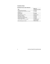
... terminator (or second processor) Install the VRM Install memory Remove the access cover Install the I/O shield Rearrange the standoffs Install the server board bumpers Install the server board Connect cables to the server board Finish setting up your chassis Where the ...information is located This guide This guide This guide This guide Chassis manual This guide This guide This guide This guide This guide and the chassis manual Chassis manual 4 Intel Server Board STL2...
... terminator (or second processor) Install the VRM Install memory Remove the access cover Install the I/O shield Rearrange the standoffs Install the server board bumpers Install the server board Connect cables to the server board Finish setting up your chassis Where the ...information is located This guide This guide This guide This guide Chassis manual This guide This guide This guide This guide This guide and the chassis manual Chassis manual 4 Intel Server Board STL2...

Quick Start Guide
Page 16
C B A OM10677 16 STL2 Server Board Quick Start Guide Install the Voltage Regulator Module If you are installing two processors, you must install a voltage regulator module (VRM). Make sure the plastic latches engage the VRM. Orient the VRM as shown and press it into the connector.
C B A OM10677 16 STL2 Server Board Quick Start Guide Install the Voltage Regulator Module If you are installing two processors, you must install a voltage regulator module (VRM). Make sure the plastic latches engage the VRM. Orient the VRM as shown and press it into the connector.