
Product Guide
Page 5
...Heatsink...24 8. Replacing the Back up Battery 70 7 Equipment Log and Power Consumption Worksheets Equipment Log ...71 Current Usage ...73 Calculating Power Consumption 73 Index...77 Figures 1. CPU Clock Speed (5E1 26 4. Power Usage Worksheet 2 75 Contents v Lower the Locking Bar 23 7. Server Board...Declaration of Conformity 68 BSMI (Taiwan) ...69 Replacing the Back up Battery 29 14. Server Board Connector and Component Locations 9 3. Connect the Processor Fan 25 10. Processor Clock Speed Jumper 26 11. Jumper Locations ...65 Tables 1. Software Security Features 17 ...
...Heatsink...24 8. Replacing the Back up Battery 70 7 Equipment Log and Power Consumption Worksheets Equipment Log ...71 Current Usage ...73 Calculating Power Consumption 73 Index...77 Figures 1. CPU Clock Speed (5E1 26 4. Power Usage Worksheet 2 75 Contents v Lower the Locking Bar 23 7. Server Board...Declaration of Conformity 68 BSMI (Taiwan) ...69 Replacing the Back up Battery 29 14. Server Board Connector and Component Locations 9 3. Connect the Processor Fan 25 10. Processor Clock Speed Jumper 26 11. Jumper Locations ...65 Tables 1. Software Security Features 17 ...

Product Guide
Page 9
... . Primary processor heatsink fan connector (P12) Figure 2. Secondary processor (P14) F. Ultra160 LVD SCSI connector (P8) S. Configuration jumper block (1L4) G. System fan connector FAN3A (P29) M. System fan connector FAN1 (P11) Z. Server Board Connector and Component... (P33) N. Power supply signal connector (P37) H. IDE connector (P19) J. Secondary processor heatsink fan connector (P36) Q. Configuration jumper block (1J15) U. Two pin speaker connector (P31) L. Server Board Connector and Component Locations A B C D EF G H AA I Z J K L Y M NO X P Q ...
... . Primary processor heatsink fan connector (P12) Figure 2. Secondary processor (P14) F. Ultra160 LVD SCSI connector (P8) S. Configuration jumper block (1L4) G. System fan connector FAN3A (P29) M. System fan connector FAN1 (P11) Z. Server Board Connector and Component... (P33) N. Power supply signal connector (P37) H. IDE connector (P19) J. Secondary processor heatsink fan connector (P36) Q. Configuration jumper block (1J15) U. Two pin speaker connector (P31) L. Server Board Connector and Component Locations A B C D EF G H AA I Z J K L Y M NO X P Q ...
Product Guide
Page 24
OM10680 Figure 7. PGA370 A B Figure 8. Then use a screw driver or other tool to the processor socket. Place the fan heatsink on top of the processor. We recommend attaching the side away from the fan cable first. Attach the Heatsink OM10681 24 Intel Server Board STL2 Product Guide Attach the fan heatsink clip to attach the remaining side. 6. Place the Heatsink 7.
OM10680 Figure 7. PGA370 A B Figure 8. Then use a screw driver or other tool to the processor socket. Place the fan heatsink on top of the processor. We recommend attaching the side away from the fan cable first. Attach the Heatsink OM10681 24 Intel Server Board STL2 Product Guide Attach the fan heatsink clip to attach the remaining side. 6. Place the Heatsink 7.

Product Guide
Page 27
... chapter and the additional cautions given here. 2. Observe the safety and ESD precautions at the beginning of the processor terminator with your processor for more detail. 4. Installing a Terminator OM10679 Upgrading 27 Removing a Processor 1. Unplug the heatsink fan. 3. Aligning the pins of this chapter and the additional cautions given here. 2. Raise the locking bar on...
... chapter and the additional cautions given here. 2. Observe the safety and ESD precautions at the beginning of the processor terminator with your processor for more detail. 4. Installing a Terminator OM10679 Upgrading 27 Removing a Processor 1. Unplug the heatsink fan. 3. Aligning the pins of this chapter and the additional cautions given here. 2. Raise the locking bar on...

Quick Start Guide
Page 12
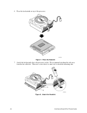
5 Place the fan heatsink on top of the processor. OM10680 12 STL2 Server Board Quick Start Guide
5 Place the fan heatsink on top of the processor. OM10680 12 STL2 Server Board Quick Start Guide
Quick Start Guide
Page 13
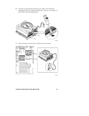
OM10681 P36 P12 PGA370 Intel Server Board STL2 Quick Start Guide OM10671 13 6 Attach the fan heatsink clip to attach the remaining side. Then use a screw driver or other tool to the processor socket. PGA370 A B 7 Connect the processor fan cable to the processor fan connector. We recommend attaching the side away from the fan cable first.
OM10681 P36 P12 PGA370 Intel Server Board STL2 Quick Start Guide OM10671 13 6 Attach the fan heatsink clip to attach the remaining side. Then use a screw driver or other tool to the processor socket. PGA370 A B 7 Connect the processor fan cable to the processor fan connector. We recommend attaching the side away from the fan cable first.


