
User Guide
Page 3
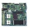
... Intel® Server Board SE7520JR2. Intel® Server Board SE7520JR2 User Guide iii Use this chapter, you will find a list of the server board features, photos of the Server Board SE7520JR2. This includes how to navigate through the BIOS Setup screens, how to perform a BIOS update, and how to the Technical Product Specification. See "Additional Information and Software" for Intel products, see http://support.intel.com/support/motherboards/server/SE7520JR2...
... Intel® Server Board SE7520JR2. Intel® Server Board SE7520JR2 User Guide iii Use this chapter, you will find a list of the server board features, photos of the Server Board SE7520JR2. This includes how to navigate through the BIOS Setup screens, how to perform a BIOS update, and how to the Technical Product Specification. See "Additional Information and Software" for Intel products, see http://support.intel.com/support/motherboards/server/SE7520JR2...

User Guide
Page 4
... software name in the search field at http://support.intel.com/support/motherboards/server/SE7520JR2 Accessories or other Intel server products Spares and Configuration Guide Hardware (peripheral boards, adapter cards) and operating systems that have been tested with this product Tested HardwareOperating Systems List Chassis that have been tested with this product Processors that have been tested with this product...
... software name in the search field at http://support.intel.com/support/motherboards/server/SE7520JR2 Accessories or other Intel server products Spares and Configuration Guide Hardware (peripheral boards, adapter cards) and operating systems that have been tested with this product Tested HardwareOperating Systems List Chassis that have been tested with this product Processors that have been tested with this product...
User Guide
Page 13
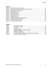
... Jumper Location 19 Figure 4. Table 3. Server Board Features 16 Configuration Jumper 19 NIC LEDs...20 Processor Support 21 DIMM Module Memory Capacity Support 22 Keyboard Commands 35 POST Error Beep Codes 49 Error Beep Codes Provided by Intel® Management Modules 49 Product Certification Markings 52 Intel® Server Board SE7520JR2 User Guide xiii Server Board Connector and Component Locations 18 Figure...
... Jumper Location 19 Figure 4. Table 3. Server Board Features 16 Configuration Jumper 19 NIC LEDs...20 Processor Support 21 DIMM Module Memory Capacity Support 22 Keyboard Commands 35 POST Error Beep Codes 49 Error Beep Codes Provided by Intel® Management Modules 49 Product Certification Markings 52 Intel® Server Board SE7520JR2 User Guide xiii Server Board Connector and Component Locations 18 Figure...

User Guide
Page 16
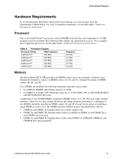
... modules One low-profile riser slot that follow either PCI-X or PCI-Express* specifications. One full-height riser slot, utilizing Intel® Adaptive Slot technology. Server Board Features Feature Description Processors Memory Chipset Support for 10/100/1000 Mb connections Two USB 2.0 ports U320 high-density 80-pin SCSI connector (channel B) (SC7520JR2SCSID1 and SC7520SCSID2 only...
... modules One low-profile riser slot that follow either PCI-X or PCI-Express* specifications. One full-height riser slot, utilizing Intel® Adaptive Slot technology. Server Board Features Feature Description Processors Memory Chipset Support for 10/100/1000 Mb connections Two USB 2.0 ports U320 high-density 80-pin SCSI connector (channel B) (SC7520JR2SCSID1 and SC7520SCSID2 only...

User Guide
Page 17
... single speed processor fan connectors One 3-pin system fan connector with either of supporting up to an optional backplane providing Optical Drive support when using the National Semiconductor* PC87431M mini-Baseboard Management Controller (mBMC) (Default). Support for Intel® Server Management 8.x Intel® Light-Guided Diagnostics on all field replaceable units (FRUs) Intel® Server Board SE7520JR2 User Guide 17 Server Board Features...
... single speed processor fan connectors One 3-pin system fan connector with either of supporting up to an optional backplane providing Optical Drive support when using the National Semiconductor* PC87431M mini-Baseboard Management Controller (mBMC) (Default). Support for Intel® Server Management 8.x Intel® Light-Guided Diagnostics on all field replaceable units (FRUs) Intel® Server Board SE7520JR2 User Guide 17 Server Board Features...
User Guide
Page 21
... of DIMM sockets 1B, 2B, and 3B. Processor Support Processor Family FSB Frequency Intel® Xeon™ 800 MHz Intel® Xeon™ 800 MHz Intel® Xeon™ 800 MHz Intel® Xeon™ 800 MHz Intel® Xeon™ 800 MHz Frequency 2.8 GHz 3.0 GHz 3.2 GHz 3.4 GHz 3.6 GHz Memory The Server Board SE7520JR2 provides six DIMM sockets across two channels...
... of DIMM sockets 1B, 2B, and 3B. Processor Support Processor Family FSB Frequency Intel® Xeon™ 800 MHz Intel® Xeon™ 800 MHz Intel® Xeon™ 800 MHz Intel® Xeon™ 800 MHz Intel® Xeon™ 800 MHz Frequency 2.8 GHz 3.0 GHz 3.2 GHz 3.4 GHz 3.6 GHz Memory The Server Board SE7520JR2 provides six DIMM sockets across two channels...
User Guide
Page 25
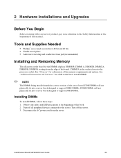
..., DIMM1A, DIMM2B, DIMM2A, DIMM3B, DIMM3A starting from the server. Turn off all peripheral devices connected to the server. Intel® Server Board SE7520JR2 User Guide 25 DDR DIMMs will not physically fit into a server board designed to support DDR2 DIMMs. DDR2 DIMMs will not physically fit into a server board designed to the processor socket. 2 Hardware Installations and Upgrades Before You Begin Before...
..., DIMM1A, DIMM2B, DIMM2A, DIMM3B, DIMM3A starting from the server. Turn off all peripheral devices connected to the server. Intel® Server Board SE7520JR2 User Guide 25 DDR DIMMs will not physically fit into a server board designed to support DDR2 DIMMs. DDR2 DIMMs will not physically fit into a server board designed to the processor socket. 2 Hardware Installations and Upgrades Before You Begin Before...

User Guide
Page 31
... and Upgrades 10. As the server board is shipped, it is configured to support DCD signals. 1. See Figure10 6. Changing the Serial Port Configuration Intel® Server Board SE7520JR2 User Guide 31 Use the following instructions to configure your server chassis for the serial port. Turn off all peripheral devices connected to the server. Disconnect the AC power cord from...
... and Upgrades 10. As the server board is shipped, it is configured to support DCD signals. 1. See Figure10 6. Changing the Serial Port Configuration Intel® Server Board SE7520JR2 User Guide 31 Use the following instructions to configure your server chassis for the serial port. Turn off all peripheral devices connected to the server. Disconnect the AC power cord from...

User Guide
Page 40
... ? ‰ Are all integrated components from the tested components lists? Check the tested memory, and chassis lists, as well as the supported hardware and operating system list. Refer to the operating system documentation. ‰ Did you are usually caused by an incorrect installation or configuration...Is AC power available at the AC source. ‰ Are all cables correctly connected and secured? ‰ Are the processors fully seated in their sockets on the server board? ‰ Are all standoffs in the proper location and not touching any components, causing a potential short? ‰ Are...
... ? ‰ Are all integrated components from the tested components lists? Check the tested memory, and chassis lists, as well as the supported hardware and operating system list. Refer to the operating system documentation. ‰ Did you are usually caused by an incorrect installation or configuration...Is AC power available at the AC source. ‰ Are all cables correctly connected and secured? ‰ Are the processors fully seated in their sockets on the server board? ‰ Are all standoffs in the proper location and not touching any components, causing a potential short? ‰ Are...

User Guide
Page 49
...addition to take 1 Control panel CMOS clear has been initiated. 1-5-1-1 Processor failure. Table 7. Intel® Server Board SE7520JR2 User Guide 49 If on-board video is empty. Reseat or replace the failed processor. 1-5-2-3 Processor configuration error or CPU 1 socket is installed. Please note that not ...Error Beep Codes Provided by Intel® Management Modules Beep Code Reason for the beeps and action to the beep codes above, additional beep codes are supported by BIOS beep codes. In a two-processor system, make sure the processors are removed, insert the ...
...addition to take 1 Control panel CMOS clear has been initiated. 1-5-1-1 Processor failure. Table 7. Intel® Server Board SE7520JR2 User Guide 49 If on-board video is empty. Reseat or replace the failed processor. 1-5-2-3 Processor configuration error or CPU 1 socket is installed. Please note that not ...Error Beep Codes Provided by Intel® Management Modules Beep Code Reason for the beeps and action to the beep codes above, additional beep codes are supported by BIOS beep codes. In a two-processor system, make sure the processors are removed, insert the ...


