
Product Guide
Page 1
Intel® Server Board SE7501BR2 Product Guide A Guide for Technically Qualified Assemblers of Intel® Identified Subassemblies/Products Order Number: A97020-002
Intel® Server Board SE7501BR2 Product Guide A Guide for Technically Qualified Assemblers of Intel® Identified Subassemblies/Products Order Number: A97020-002

Product Guide
Page 3
...Field Replaceable Units and Sensor Data Records 22 System Event Log ...22 Platform Event Management 22 Emergency Management Port 23 Intel® Server Management 24 Security ...25 Secure Mode ...26 Password Protection 27 Intrusion Switch Monitoring 28 Floppy Write Protection 28 Fixed ......32 Installing the I/O Gasket and Shield 32 Installing Chassis Standoffs 34 Installing the Rubber Bumper 35 Installing the Server Board 36 Making Connections to the Server Board 37 Cable Routing...38 Installing or Replacing Processor(s 39 Installing Memory ...52 Finishing Up ...53 Replacing the Back...
...Field Replaceable Units and Sensor Data Records 22 System Event Log ...22 Platform Event Management 22 Emergency Management Port 23 Intel® Server Management 24 Security ...25 Secure Mode ...26 Password Protection 27 Intrusion Switch Monitoring 28 Floppy Write Protection 28 Fixed ......32 Installing the I/O Gasket and Shield 32 Installing Chassis Standoffs 34 Installing the Rubber Bumper 35 Installing the Server Board 36 Making Connections to the Server Board 37 Cable Routing...38 Installing or Replacing Processor(s 39 Installing Memory ...52 Finishing Up ...53 Replacing the Back...

Product Guide
Page 4
... BIOS Upgrade 74 Changing the BIOS Language 75 Hot Keys ...75 4 Configuration Software and Utilities 77 System Software Update Sequence 77 Server Configuration Wizard 78 Direct Platform Control (DPC) Console 79 DPC Console Modes of Operation 80 Running the DPC Console 80 Using the... Setting a System Asset Tag 98 Creating Diskettes...98 Installing a Service Partition (Optional 99 Saving and Restoring Using the Intel Server tMheanSaygsetemmenCt oannfdigIunrtaetli®onS.M...a..R...T...T..o..o..l..(.O...p.t..io..n..a..l 110002 4 Intel Server Board SE7501BR2 Product Guide
... BIOS Upgrade 74 Changing the BIOS Language 75 Hot Keys ...75 4 Configuration Software and Utilities 77 System Software Update Sequence 77 Server Configuration Wizard 78 Direct Platform Control (DPC) Console 79 DPC Console Modes of Operation 80 Running the DPC Console 80 Using the... Setting a System Asset Tag 98 Creating Diskettes...98 Installing a Service Partition (Optional 99 Saving and Restoring Using the Intel Server tMheanSaygsetemmenCt oannfdigIunrtaetli®onS.M...a..R...T...T..o..o..l..(.O...p.t..io..n..a..l 110002 4 Intel Server Board SE7501BR2 Product Guide

Product Guide
Page 5
Installing Intel Server Management 103 Installing Intel SMaRT Tool 103 5 Solving Problems 105 Resetting the System ...105 Initial System Startup ...105 Checklist...105 Running New Application Software 106 Checklist...106 After the ... Does Not Light 110 Hard Disk Drive Activity Light Does Not Light 110 CD-ROM Drive Activity Light Does Not Light 110 Cannot Connect to a Server 110 Problems with Network 111 PCI Installation Tips 111 Problems with Application Software 111 Bootable CD-ROM Is Not Detected 111 Recovering the BIOS...112...
Installing Intel Server Management 103 Installing Intel SMaRT Tool 103 5 Solving Problems 105 Resetting the System ...105 Initial System Startup ...105 Checklist...105 Running New Application Software 106 Checklist...106 After the ... Does Not Light 110 Hard Disk Drive Activity Light Does Not Light 110 CD-ROM Drive Activity Light Does Not Light 110 Cannot Connect to a Server 110 Problems with Network 111 PCI Installation Tips 111 Problems with Application Software 111 Bootable CD-ROM Is Not Detected 111 Recovering the BIOS...112...

Product Guide
Page 6
...the Heat Sink Clip 51 Figure 26. Configuration Jumper Location 119 Figure 33. Front Panel Header Connection Location 120 6 Intel Server Board SE7501BR2 Product Guide Configuring Chassis Standoffs 34 Figure 7. Installing the Processor Retention Brackets 47 Figure 20. Installing the Heat Sink 50... Figure 25. BIOS Recovery Jumper 112 Figure 30. Attaching the Server Board 36 Figure 9. Making Connections to the Retention Mechanism 45 Figure 18. Attaching Retention Mechanism 41 Figure 13. Lower Locking...
...the Heat Sink Clip 51 Figure 26. Configuration Jumper Location 119 Figure 33. Front Panel Header Connection Location 120 6 Intel Server Board SE7501BR2 Product Guide Configuring Chassis Standoffs 34 Figure 7. Installing the Processor Retention Brackets 47 Figure 20. Installing the Heat Sink 50... Figure 25. BIOS Recovery Jumper 112 Figure 30. Attaching the Server Board 36 Figure 9. Making Connections to the Retention Mechanism 45 Figure 18. Attaching Retention Mechanism 41 Figure 13. Lower Locking...

Product Guide
Page 7
...26. Table 30. Table 3. Table 6. Table 28. Table 35. Table 2. Table 5. Table 22. Table 29. Table 8. Table 32. Server Board Features 9 64-bit PCI Segment Configuration 15 10/100 Megabit LEDs (NIC1 19 Gigabit LEDs (NIC2 19 Security Operation Summary 25 Keyboard Commands 59... Devices Submenu 63 Peripheral Configuration Submenu 64 Memory Configuration Submenu 65 Advanced Chipset Control Submenu 65 Security Menu 66 Server Menu 67 System Management Submenu 68 Console Redirection Submenu 69 Event Log Configuration Submenu 70 Fault Resilient Booting Submenu 70...
...26. Table 30. Table 3. Table 6. Table 28. Table 35. Table 2. Table 5. Table 22. Table 29. Table 8. Table 32. Server Board Features 9 64-bit PCI Segment Configuration 15 10/100 Megabit LEDs (NIC1 19 Gigabit LEDs (NIC2 19 Security Operation Summary 25 Keyboard Commands 59... Devices Submenu 63 Peripheral Configuration Submenu 64 Memory Configuration Submenu 65 Advanced Chipset Control Submenu 65 Security Menu 66 Server Menu 67 System Management Submenu 68 Console Redirection Submenu 69 Event Log Configuration Submenu 70 Fault Resilient Booting Submenu 70...
Product Guide
Page 9
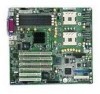
...Server Board Features The Intel® Server Board SE7501BR2 offers a "flat" design, with 512KB L2 Cache in the Flip-chipmicro Pin Grid Array2 (FC-mPGA2) or in the Interposer micro Pin Grid Array (INT-mPGA) package. Server Board Features Feature Processor Chipset Memory Video PCI bus Network Integrated SCSI Description Dual 533 or 400 FSB Intel... operation. Table 1. The server board supports dual-processor operation with the Intel® E7501 chipset and the Intel® Xeon™ processors with the processors and memory subsystems residing on motherboard (M-ROMB) support provided via...
...Server Board Features The Intel® Server Board SE7501BR2 offers a "flat" design, with 512KB L2 Cache in the Flip-chipmicro Pin Grid Array2 (FC-mPGA2) or in the Interposer micro Pin Grid Array (INT-mPGA) package. Server Board Features Feature Processor Chipset Memory Video PCI bus Network Integrated SCSI Description Dual 533 or 400 FSB Intel... operation. Table 1. The server board supports dual-processor operation with the Intel® E7501 chipset and the Intel® Xeon™ processors with the processors and memory subsystems residing on motherboard (M-ROMB) support provided via...

Product Guide
Page 10
...; Floppy write-protect Form Factor Server Management1 IPMI 1.5 compliant • SSI-EEB 3.0 compliant form factor Intel® Baseboard Management Controller (BMC) Intel® Server Management (ISM) software Version 5.5,...Server Configuration Wizard (SCW) • Intel® SMaRT Tool Integration • Online Rolling BIOS & Firmware Upgrade • Command Line Interface over LAN • ID LED Server Management Support 1 For additional information refer to the Intel® Server Management ver 5.5 Installation & User's Guide available on the ISM CD. 10 Intel Server Board SE7501BR2...
...; Floppy write-protect Form Factor Server Management1 IPMI 1.5 compliant • SSI-EEB 3.0 compliant form factor Intel® Baseboard Management Controller (BMC) Intel® Server Management (ISM) software Version 5.5,...Server Configuration Wizard (SCW) • Intel® SMaRT Tool Integration • Online Rolling BIOS & Firmware Upgrade • Command Line Interface over LAN • ID LED Server Management Support 1 For additional information refer to the Intel® Server Management ver 5.5 Installation & User's Guide available on the ISM CD. 10 Intel Server Board SE7501BR2...

Product Guide
Page 12
... Connect DIMM Memory Connect DIMM Memory Connect USB E AB C DF G A. Keyboard / Mouse C. Parallel F. NIC1 (10/100 Mb) OM14663 Figure 2. Back Panel Connectors Intel® Chipset The Intel® Server Board SE7501BR2 includes the Intel E7501 chipset (MCH, ICH3, P64H2), which provides an integrated I/O bridge and memory controller, and a flexible I /O Bridge) • An HI 1.5 bus that provides...
... Connect DIMM Memory Connect DIMM Memory Connect USB E AB C DF G A. Keyboard / Mouse C. Parallel F. NIC1 (10/100 Mb) OM14663 Figure 2. Back Panel Connectors Intel® Chipset The Intel® Server Board SE7501BR2 includes the Intel E7501 chipset (MCH, ICH3, P64H2), which provides an integrated I/O bridge and memory controller, and a flexible I /O Bridge) • An HI 1.5 bus that provides...

Product Guide
Page 13
...of the PCI-X segments of the P64H2 is to provide the gateway to generate edge- When enabled, each port can be used on the SE7501BR2 server board. BIOS programming of the ICH3 is to provide an integrated I/O bridge to add-in cards. A DH10 10-pin serial header is provided ...on the baseboard for add-in cards. Parallel Port The SE7501BR2 baseboard provides a 25-pin parallel port back panel connector. The Adaptec AIC-7901 embedded controller is enabled via one of four different COM ports...
...of the PCI-X segments of the P64H2 is to provide the gateway to generate edge- When enabled, each port can be used on the SE7501BR2 server board. BIOS programming of the ICH3 is to provide an integrated I/O bridge to add-in cards. A DH10 10-pin serial header is provided ...on the baseboard for add-in cards. Parallel Port The SE7501BR2 baseboard provides a 25-pin parallel port back panel connector. The Adaptec AIC-7901 embedded controller is enabled via one of four different COM ports...

Product Guide
Page 14
... Controllers (APICs) in the ICH3 and P64H2. Floppy Disk Connector The floppy disk connector on the server board provides the interface to the instructions provided in this chassis, see : http://support.intel.com/support/motherboards/server/SE7501BR2 Dual Processor Operation The Intel Xeon processor interface is dual-processor (DP)-ready. For proper processor cooling, the fan inlet...
... Controllers (APICs) in the ICH3 and P64H2. Floppy Disk Connector The floppy disk connector on the server board provides the interface to the instructions provided in this chassis, see : http://support.intel.com/support/motherboards/server/SE7501BR2 Dual Processor Operation The Intel Xeon processor interface is dual-processor (DP)-ready. For proper processor cooling, the fan inlet...

Product Guide
Page 15
... via two separate memory buses. In other words, the bus will operate at the speed of DDR266 memory. Although the SE7501BR2 server board architecture allows the user to 8 GB of the slowest installed card. the memory on that are supported, including: •...up to four ECC DDR DIMMs that bus determines the bus mode/speed. The server board supports up to mix various sizes of tested memory, see: http://support.intel.com/support/motherboards/server/SE7501BR2 PCI I/O Subsystem The SE7501BR2 server board provides three PCI bus segments: • Segment C with two PCI-X 64-...
... via two separate memory buses. In other words, the bus will operate at the speed of DDR266 memory. Although the SE7501BR2 server board architecture allows the user to 8 GB of the slowest installed card. the memory on that are supported, including: •...up to four ECC DDR DIMMs that bus determines the bus mode/speed. The server board supports up to mix various sizes of tested memory, see: http://support.intel.com/support/motherboards/server/SE7501BR2 PCI I/O Subsystem The SE7501BR2 server board provides three PCI bus segments: • Segment C with two PCI-X 64-...

Product Guide
Page 16
... is configured with two PCI-X 64/133 cards the bus will be programmed by the BIOS according to the speed of the slowest adapter. 16 Intel Server Board SE7501BR2 Product Guide If you install a slower card into one of the PCI-X 64/100 connectors, the bus speed for both connectors will be lowered to...
... is configured with two PCI-X 64/133 cards the bus will be programmed by the BIOS according to the speed of the slowest adapter. 16 Intel Server Board SE7501BR2 Product Guide If you install a slower card into one of the PCI-X 64/100 connectors, the bus speed for both connectors will be lowered to...

Product Guide
Page 17
... colors with some ROMB RAID controllers. The SE7501BR2 server board provides a standard 15-pin VGA connector, and external video blanking logic for TFT displays, and up to 100Hz. Description 17 Modular RAID on Motherboard The SE7501BR2 server board supports M-ROMB or Zero Channel RAID (ZCR...) that allows the on-board SCSI controller to a peak of 132 MB/s • 8-, 16-, or 32-bit data transfers • Plug-and-Play ready • Parity enabled Video Controller The Intel® Server Board SE7501BR2...
... colors with some ROMB RAID controllers. The SE7501BR2 server board provides a standard 15-pin VGA connector, and external video blanking logic for TFT displays, and up to 100Hz. Description 17 Modular RAID on Motherboard The SE7501BR2 server board supports M-ROMB or Zero Channel RAID (ZCR...) that allows the on-board SCSI controller to a peak of 132 MB/s • 8-, 16-, or 32-bit data transfers • Plug-and-Play ready • Parity enabled Video Controller The Intel® Server Board SE7501BR2...
Product Guide
Page 18
Network Interface Controllers (NICs) The Intel® Server Board SE7501BR2 includes one 10/100Base-TX network connection, based on the Intel 82550PM Fast Ethernet Controller (NIC1)5, and one 10/100/1000Base-TX network connection, based on the left, next to the operating system. &#...connector interface. A flash device stores the network ID • Support for concurrent processing of the system, the gigabit controller is the designated Intel Server Management NIC. 18 Intel Server Board SE7501BR2 Product Guide When disabled, the controller(s) are not visible to the video connector.
Network Interface Controllers (NICs) The Intel® Server Board SE7501BR2 includes one 10/100Base-TX network connection, based on the Intel 82550PM Fast Ethernet Controller (NIC1)5, and one 10/100/1000Base-TX network connection, based on the left, next to the operating system. &#...connector interface. A flash device stores the network ID • Support for concurrent processing of the system, the gigabit controller is the designated Intel Server Management NIC. 18 Intel Server Board SE7501BR2 Product Guide When disabled, the controller(s) are not visible to the video connector.

Product Guide
Page 19
...indicates 10-Mbps when it is off and100 Mbps operation when it is on its RJ45 connector; Table 4. NIC Connector and Status LEDs The Intel® Server Board SE7501BR2 supports two RJ45 connectors, one for the 10/100-Megabit Fast Ethernet controller (NIC1), and the other for an overview. Gigabit LEDs (NIC2)...) On Blinking NIC1 State 10-Mbps 100-Mbps On Transmit / Receive activity NIC2 drives two LEDs located on the LAN and the speed of the board. These LEDs indicate link/activity on its RJ45 connector. Table 3. 10/100 Megabit LEDs (NIC1) LED Color LED State Off Green (left )...
...indicates 10-Mbps when it is off and100 Mbps operation when it is on its RJ45 connector; Table 4. NIC Connector and Status LEDs The Intel® Server Board SE7501BR2 supports two RJ45 connectors, one for the 10/100-Megabit Fast Ethernet controller (NIC1), and the other for an overview. Gigabit LEDs (NIC2)...) On Blinking NIC1 State 10-Mbps 100-Mbps On Transmit / Receive activity NIC2 drives two LEDs located on the LAN and the speed of the board. These LEDs indicate link/activity on its RJ45 connector. Table 3. 10/100 Megabit LEDs (NIC1) LED Color LED State Off Green (left )...

Product Guide
Page 20
...the system into a state in which the hard drives spin-down the system. The server board supports sleep states S0, S1, S4, and S5. When the server board is running state. • S1: DC Power remains on -board NICs to use standard, but are saved to the system while it powered down ...or another wakeup event restores the system state from a wakeup event. • S4: Hibernate or Save to provide BIOS boot option. 20 Intel Server Board SE7501BR2 Product Guide Only the RTC section of the system and the OS policy determines the entry methods and wake-up , plus the ability to ...
...the system into a state in which the hard drives spin-down the system. The server board supports sleep states S0, S1, S4, and S5. When the server board is running state. • S1: DC Power remains on -board NICs to use standard, but are saved to the system while it powered down ...or another wakeup event restores the system state from a wakeup event. • S4: Hibernate or Save to provide BIOS boot option. 20 Intel Server Board SE7501BR2 Product Guide Only the RTC section of the system and the OS policy determines the entry methods and wake-up , plus the ability to ...

Product Guide
Page 21
...described, refer to the Configuration Software and Utilities chapter, beginning on by an RTC trigger event. Baseboard Management Controller Intel server boards incorporate a baseboard management controller (BMC), which is provided below. Description 21 A brief description of the features is ...sensors. • Manages nonvolatile storage for system management activities. System Management Intel integrates system management features into the hardware and provides additional features through Intel® Server Management (ISM) software version 5.5. Wake on RTC Alarm Wake on RTC ...
...described, refer to the Configuration Software and Utilities chapter, beginning on by an RTC trigger event. Baseboard Management Controller Intel server boards incorporate a baseboard management controller (BMC), which is provided below. Description 21 A brief description of the features is ...sensors. • Manages nonvolatile storage for system management activities. System Management Intel integrates system management features into the hardware and provides additional features through Intel® Server Management (ISM) software version 5.5. Wake on RTC Alarm Wake on RTC ...

Product Guide
Page 22
...panel switch • Watchdog timer reset, power down, or power cycle • System restart (reboot) 22 Intel Server Board SE7501BR2 Product Guide The BMC stores SDR information in the server. You can also log events by using the System Setup Utility. You should also run the FRU/SDR ...The BMC stores FRU information for monitoring. For these reasons, it records significant or critical system events. The SEL is configured. Intel® server boards are major modules in a nonvolatile storage component on the baseboard. You can be configured when the system is stored in the ...
...panel switch • Watchdog timer reset, power down, or power cycle • System restart (reboot) 22 Intel Server Board SE7501BR2 Product Guide The BMC stores SDR information in the server. You can also log events by using the System Setup Utility. You should also run the FRU/SDR ...The BMC stores FRU information for monitoring. For these reasons, it records significant or critical system events. The SEL is configured. Intel® server boards are major modules in a nonvolatile storage component on the baseboard. You can be configured when the system is stored in the ...

Product Guide
Page 23
... predefined paging string. You can configure the EMP by using either the operating system or the EMP will never be configured in Intel Server Management. If you have configured the Serial B port for use as the Direct Platform Control or the Client System Setup Utility ...from a remote console. Description 23 The operating system will control the port, depending on your configuration. Use the Server Configuration Wizard to a predefined destination on the board can configure these forms: • Platform Event Pages - The BMC controls the port and interfaces with either an...
... predefined paging string. You can configure the EMP by using either the operating system or the EMP will never be configured in Intel Server Management. If you have configured the Serial B port for use as the Direct Platform Control or the Client System Setup Utility ...from a remote console. Description 23 The operating system will control the port, depending on your configuration. Use the Server Configuration Wizard to a predefined destination on the board can configure these forms: • Platform Event Pages - The BMC controls the port and interfaces with either an...


