
Product Specification
Page 2
Revision History Intel® Entry Server Board SE7221BA1-E TPS Revision History Date September 30, 2004 Oct 20, 2004 Nov 11, 2004 Dec 31, 2004 Jan 4, 2004 Jan 25, 2005 Sep 16, 2005 Oct 5, 2005 Apr 10, 2006 Revision Number 0.8 0.9 0.99 1.00 1.1 1.2 1.3 1.4 1.5 Initial Draft Modifications Second Draft Final Draft Release Web links updated Updated Updated with supported video resolutions Update the memory information Updated release ii Revision 1.5
Revision History Intel® Entry Server Board SE7221BA1-E TPS Revision History Date September 30, 2004 Oct 20, 2004 Nov 11, 2004 Dec 31, 2004 Jan 4, 2004 Jan 25, 2005 Sep 16, 2005 Oct 5, 2005 Apr 10, 2006 Revision Number 0.8 0.9 0.99 1.00 1.1 1.2 1.3 1.4 1.5 Initial Draft Modifications Second Draft Final Draft Release Web links updated Updated Updated with supported video resolutions Update the memory information Updated release ii Revision 1.5

Product Specification
Page 4
...Reset Configuration Logic 6 3.1.3 Processor Module Presence Detection 6 3.1.4 Processor Support 6 3.1.5 Interrupts and APIC 7 3.2 Memory Subsystem 7 3.2.1 DIMM Socket Features 7 3.2.2 Supported DIMM Configurations 8 3.2.3 Memory Configurations 8 3.3 Intel 7221 Chipset 12 3.3.1 USB Interface ...12 3.3.2 IDE Support ...12 3.3.3 Real-Time Clock, CMOS SRAM, ...1.5 Server Board Overview ...3 2.1 Intel® Entry Server Board SE7221BA1-E SKU Availability 3 2.2 Intel® Entry Server Board SE7221BA1-E Feature Set 3 2.3 Block Diagram ...4 2.4 Board Layout ...5 3. Table ...
...Reset Configuration Logic 6 3.1.3 Processor Module Presence Detection 6 3.1.4 Processor Support 6 3.1.5 Interrupts and APIC 7 3.2 Memory Subsystem 7 3.2.1 DIMM Socket Features 7 3.2.2 Supported DIMM Configurations 8 3.2.3 Memory Configurations 8 3.3 Intel 7221 Chipset 12 3.3.1 USB Interface ...12 3.3.2 IDE Support ...12 3.3.3 Real-Time Clock, CMOS SRAM, ...1.5 Server Board Overview ...3 2.1 Intel® Entry Server Board SE7221BA1-E SKU Availability 3 2.2 Intel® Entry Server Board SE7221BA1-E Feature Set 3 2.3 Block Diagram ...4 2.4 Board Layout ...5 3. Table ...

Product Specification
Page 5
...Jumper Blocks ...37 7. System BIOS ...39 7.1 BIOS Identification String 39 7.2 Introduction ...39 Revision 1.5 v Intel® Entry Server Board SE7221BA1-E TPS Table of Contents 3.6.1 Advanced Configuration and Power Interface (ACPI 16 3.6.2 System States and Power States 17... 3.6.3 Hardware Support 18 4. Maps and Interrupts ...21 4.1 Memory Resources 21 4.1.1 Memory Map ...21 4.1.2 Addressable Memory 21 4.2 Fixed ...
...Jumper Blocks ...37 7. System BIOS ...39 7.1 BIOS Identification String 39 7.2 Introduction ...39 Revision 1.5 v Intel® Entry Server Board SE7221BA1-E TPS Table of Contents 3.6.1 Advanced Configuration and Power Interface (ACPI 16 3.6.2 System States and Power States 17... 3.6.3 Hardware Support 18 4. Maps and Interrupts ...21 4.1 Memory Resources 21 4.1.1 Memory Map ...21 4.1.2 Addressable Memory 21 4.2 Fixed ...

Product Specification
Page 6
... 12.2.1 FCC Compliance Statement (USA 56 12.2.2 Canadian Compliance Statement 56 12.3 European Union Declaration of Contents Intel® Entry Server Board SE7221BA1-E TPS 7.3 BIOS Flash Memory Organization 40 7.4 Resource Configuration 40 7.4.1 PCI Autoconfiguration 40 7.4.2 PCI IDE Support ...40 7.5 System Management BIOS... Checkpoints 49 7.12 Speaker ...50 7.13 BIOS Beep Codes 50 8. General Specification...51 8.1 Intel® Entry Server Board SE7221BA1-E Power Budget 51 8.1.1 DC Loading...51 9. Error Reporting...53 10.1 Fault Resilient Booting 53 11.
... 12.2.1 FCC Compliance Statement (USA 56 12.2.2 Canadian Compliance Statement 56 12.3 European Union Declaration of Contents Intel® Entry Server Board SE7221BA1-E TPS 7.3 BIOS Flash Memory Organization 40 7.4 Resource Configuration 40 7.4.1 PCI Autoconfiguration 40 7.4.2 PCI IDE Support ...40 7.5 System Management BIOS... Checkpoints 49 7.12 Speaker ...50 7.13 BIOS Beep Codes 50 8. General Specification...51 8.1 Intel® Entry Server Board SE7221BA1-E Power Budget 51 8.1.1 DC Loading...51 9. Error Reporting...53 10.1 Fault Resilient Booting 53 11.
Product Specification
Page 8
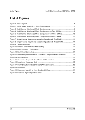
...20. Location of Figures Figure 1. I/O Shield ...60 Figure 19. Localized High Temperature Zones 62 viii Revision 1.5 Intel ® Server Board SE7221BA1-E Components 5 Figure 3. Back Panel Connectors 31 Figure 13. Dual Channel (Interleaved) Mode Configurations 9 Figure 4. ...Processor Heatsink for Front Panel USB Connectors 36 Figure 16. Thermal Monitoring...15 Figure 10. Detailed System Memory Address Map 22...
...20. Location of Figures Figure 1. I/O Shield ...60 Figure 19. Localized High Temperature Zones 62 viii Revision 1.5 Intel ® Server Board SE7221BA1-E Components 5 Figure 3. Back Panel Connectors 31 Figure 13. Dual Channel (Interleaved) Mode Configurations 9 Figure 4. ...Processor Heatsink for Front Panel USB Connectors 36 Figure 16. Thermal Monitoring...15 Figure 10. Detailed System Memory Address Map 22...
Product Specification
Page 9
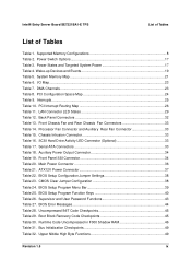
... Space Map 24 Table 9. BIOS Setup Program Menu Bar 39 Table 25. Boot Block Recovery Code Checkpoints 45 Table 30. System Memory Map 21 Table 6. Processor Fan Connector and Auxiliary Rear Fan Connector 33 Table 15. Serial ATA Connectors 33 Table 18. Power...States and Targeted System Power 17 Table 4. Runtime Code Uncompressed in F000 Shadow RAM 46 Table 31. Intel® Entry Server Board SE7221BA1-E TPS List of Tables List of Tables Table 1. Supported Memory Configurations 8 Table 2. Power Switch Options 17 Table 3. I/O Map ...23 Table 7. Interrupts...25 ...
... Space Map 24 Table 9. BIOS Setup Program Menu Bar 39 Table 25. Boot Block Recovery Code Checkpoints 45 Table 30. System Memory Map 21 Table 6. Processor Fan Connector and Auxiliary Rear Fan Connector 33 Table 15. Serial ATA Connectors 33 Table 18. Power...States and Targeted System Power 17 Table 4. Runtime Code Uncompressed in F000 Shadow RAM 46 Table 31. Intel® Entry Server Board SE7221BA1-E TPS List of Tables List of Tables Table 1. Supported Memory Configurations 8 Table 2. Power Switch Options 17 Table 3. I/O Map ...23 Table 7. Interrupts...25 ...

Product Specification
Page 13
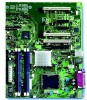
... • Intel® E7221MC Memory Controller Hub (GMCH) • Intel® 82801FR I/O Controller Hub (ICH6-R) • 8 Mbit Firmware Hub (FWH) • Support for 4 GB of Un-buffered ECC memory • Four 240-pin DDR2 SDRAM Dual Inline Memory Module (DIMM) sockets • Support for a total of range thermal values Revision 1.5 3 Intel® Entry Server Board SE7221BA1-E TPS...
... • Intel® E7221MC Memory Controller Hub (GMCH) • Intel® 82801FR I/O Controller Hub (ICH6-R) • 8 Mbit Firmware Hub (FWH) • Support for 4 GB of Un-buffered ECC memory • Four 240-pin DDR2 SDRAM Dual Inline Memory Module (DIMM) sockets • Support for a total of range thermal values Revision 1.5 3 Intel® Entry Server Board SE7221BA1-E TPS...
Product Specification
Page 16
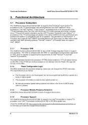
...supports Intel® EM64T (Extended Memory 64 Technology) for VTT) pin before turning on 90 nm process in the 775-land package are as the LGA775 socket. Check the Intel® web site http://support.intel.com/support/motherboards/server/se7221ba1-e/ for Intel® Pentium® 4 and Intel&#...LGA4) package technology, and plug into a 775-land LGA socket, referred to the Intel® NetBurst® microarchitecture. Functional Architecture Intel® Entry Server Board SE7221BA1-E TPS 3. The Intel® Pentium® 4 and Celeron® processors built on the VRD. The ...
...supports Intel® EM64T (Extended Memory 64 Technology) for VTT) pin before turning on 90 nm process in the 775-land package are as the LGA775 socket. Check the Intel® web site http://support.intel.com/support/motherboards/server/se7221ba1-e/ for Intel® Pentium® 4 and Intel&#...LGA4) package technology, and plug into a 775-land LGA socket, referred to the Intel® NetBurst® microarchitecture. Functional Architecture Intel® Entry Server Board SE7221BA1-E TPS 3. The Intel® Pentium® 4 and Celeron® processors built on the VRD. The ...
Product Specification
Page 17
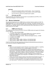
... single sided (one row) or double-sided (two row) DIMMs. 3.2.1 DIMM Socket Features: The Intel® Entry Server Board SE7221BA1-E has four DIMM sockets and supports the following memory features: • 1.8 V (only) DDR2 SDRAM DIMMs • Un-buffered, single-sided or...DIMM Check the Intel® web site http://support.intel.com/support/motherboards/server/se7221ba1-e/ for a maximum memory capacity of 4 GB. If non-SPD memory is fully seated and both latches are not supported. • 4 GB maximum total system memory. Intel® Entry Server Board SE7221BA1-E TPS Functional ...
... single sided (one row) or double-sided (two row) DIMMs. 3.2.1 DIMM Socket Features: The Intel® Entry Server Board SE7221BA1-E has four DIMM sockets and supports the following memory features: • 1.8 V (only) DDR2 SDRAM DIMMs • Un-buffered, single-sided or...DIMM Check the Intel® web site http://support.intel.com/support/motherboards/server/se7221ba1-e/ for a maximum memory capacity of 4 GB. If non-SPD memory is fully seated and both latches are not supported. • 4 GB maximum total system memory. Intel® Entry Server Board SE7221BA1-E TPS Functional ...

Product Specification
Page 18
...: • Dual channel (Interleaved) mode. If different speed DIMMs are unequal. Functional Architecture Intel® Entry Server Board SE7221BA1-E TPS • Regardless of the physical memory installed, there will always 64KB base memory and 8MB system memory occupied by system memory allocation, the left part will be used. Technology and device width can vary from one...
...: • Dual channel (Interleaved) mode. If different speed DIMMs are unequal. Functional Architecture Intel® Entry Server Board SE7221BA1-E TPS • Regardless of the physical memory installed, there will always 64KB base memory and 8MB system memory occupied by system memory allocation, the left part will be used. Technology and device width can vary from one...

Product Specification
Page 19
... shows a dual channel configuration using two DIMMs. In this example, the DIMM0 (blue) sockets of both channels are populated with Two DIMMs Revision 1.5 9 Intel® Entry Server Board SE7221BA1-E TPS 3.2.2.1 Memory channel and DIMM configuration. Dual Channel (Interleaved) Mode Configuration with identical DIMMs. 1 GB 1 GB Channel A, DIMM 0 Channel A, DIMM 1 Channel B, DIMM 0 Channel B, DIMM...
... shows a dual channel configuration using two DIMMs. In this example, the DIMM0 (blue) sockets of both channels are populated with Two DIMMs Revision 1.5 9 Intel® Entry Server Board SE7221BA1-E TPS 3.2.2.1 Memory channel and DIMM configuration. Dual Channel (Interleaved) Mode Configuration with identical DIMMs. 1 GB 1 GB Channel A, DIMM 0 Channel A, DIMM 1 Channel B, DIMM 0 Channel B, DIMM...

Product Specification
Page 21
Intel® Entry Server Board SE7221BA1-E TPS Functional Architecture 3.2.2.3 Single Channel (Asymmetric) Mode Configurations NOTE Dual channel (Interleaved) mode configurations provide the highest memory throughput. In this example, the combined capacity of the two DIMMs in Channel A does not equal the capacity of the single DIMM in the DIMM0 (...
Intel® Entry Server Board SE7221BA1-E TPS Functional Architecture 3.2.2.3 Single Channel (Asymmetric) Mode Configurations NOTE Dual channel (Interleaved) mode configurations provide the highest memory throughput. In this example, the combined capacity of the two DIMMs in Channel A does not equal the capacity of the single DIMM in the DIMM0 (...

Product Specification
Page 22
...such as follows: • Four ports are routed to two separate front panel USB connectors. 3.3.2 IDE Support The Intel® Entry Server Board SE7221BA1-E provides five IDE interface connectors: • One parallel ATA IDE connector, which supports two devices. • Four.... The ICH6-R is a centralized controller for the system bus, the memory bus, the PCI Express* Graphics bus, and the DMI interconnect. Functional Architecture Intel® Entry Server Board SE7221BA1-E TPS 3.3 Intel 7221 Chipset The Intel® 7221 chipset consists of the following modes: • Programmed I...
...such as follows: • Four ports are routed to two separate front panel USB connectors. 3.3.2 IDE Support The Intel® Entry Server Board SE7221BA1-E provides five IDE interface connectors: • One parallel ATA IDE connector, which supports two devices. • Four.... The ICH6-R is a centralized controller for the system bus, the memory bus, the PCI Express* Graphics bus, and the DMI interconnect. Functional Architecture Intel® Entry Server Board SE7221BA1-E TPS 3.3 Intel 7221 Chipset The Intel® 7221 chipset consists of the following modes: • Programmed I...

Product Specification
Page 23
...Serial ATA). 3.3.3 Real-Time Clock, CMOS SRAM, and Battery A coin-cell battery (CR2032) powers the real-time clock and CMOS memory. When the computer is being read from the logical drive, both legacy and native modes. Two physical drives, of identical size, maintain ... striping and mirroring to create one logical drive. Native mode is used for a maximum of four Serial ATA devices. Intel® Entry Server Board SE7221BA1-E TPS Functional Architecture 3.3.2.2 Serial ATA Interfaces The ICH6-R's Serial ATA controller offers four independent Serial ATA ports with a theoretical...
...Serial ATA). 3.3.3 Real-Time Clock, CMOS SRAM, and Battery A coin-cell battery (CR2032) powers the real-time clock and CMOS memory. When the computer is being read from the logical drive, both legacy and native modes. Two physical drives, of identical size, maintain ... striping and mirroring to create one logical drive. Native mode is used for a maximum of four Serial ATA devices. Intel® Entry Server Board SE7221BA1-E TPS Functional Architecture 3.3.2.2 Serial ATA Interfaces The ICH6-R's Serial ATA controller offers four independent Serial ATA ports with a theoretical...
Product Specification
Page 31
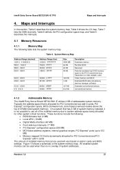
..., BIOS (firmware hub), and chipset overhead resides above the top of system addresses. Video memory and BIOS Extended BIOS data (movable by memory manager software) Extended conventional memory Conventional memory 4.1.2 Addressable Memory The Intel® Entry Server Board SE7221BA1-E utilizes 4 GB of the system memory map. EFFFF C8000 - Typically the address space that has 4 GB of the installed...
..., BIOS (firmware hub), and chipset overhead resides above the top of system addresses. Video memory and BIOS Extended BIOS data (movable by memory manager software) Extended conventional memory Conventional memory 4.1.2 Addressable Memory The Intel® Entry Server Board SE7221BA1-E utilizes 4 GB of the system memory map. EFFFF C8000 - Typically the address space that has 4 GB of the installed...

Product Specification
Page 32
Maps and Interrupts Intel® Entry Server Board SE7221BA1-E TPS 4 GB Top of System Address Space FLASH APIC Reserved ~20 MB PCI Memory Range contains PCI, chipsets, Direct Media Interface (DMI), and ICH ranges (approximately 750 MB) Top of usable DRAM (memory visible to the operating system) DRAM Range DOS Compatibility Memory 1 MB 640 KB 0 ... (64 KB) Lower BIOS area (64 KB; 16 KB x 4) Add-in Card BIOS and Buffer area (128 KB; 16 KB x 8) Standard PCI/ ISA Video Memory (SMM Memory) 128 KB DOS area (640 KB) 1 MB 960 KB 896 KB 768 KB 640 KB 0 KB OM17140 Figure 10. Detailed System...
Maps and Interrupts Intel® Entry Server Board SE7221BA1-E TPS 4 GB Top of System Address Space FLASH APIC Reserved ~20 MB PCI Memory Range contains PCI, chipsets, Direct Media Interface (DMI), and ICH ranges (approximately 750 MB) Top of usable DRAM (memory visible to the operating system) DRAM Range DOS Compatibility Memory 1 MB 640 KB 0 ... (64 KB) Lower BIOS area (64 KB; 16 KB x 4) Add-in Card BIOS and Buffer area (128 KB; 16 KB x 8) Standard PCI/ ISA Video Memory (SMM Memory) 128 KB DOS area (640 KB) 1 MB 960 KB 896 KB 768 KB 640 KB 0 KB OM17140 Figure 10. Detailed System...

Product Specification
Page 34
...Interrupts Intel® Entry Server Board SE7221BA1-E TPS DMA Channel Number 6 7 Data Width 16 bits 16 bits 4.4 PCI Configuration Space Map System Resource Open Open Table 8. PCI Configuration Space Map Bus Number (hex) Device Number (hex) Function Number (hex) Description 00 00 00 Memory ...The interrupts can be routed through either the Programmable Interrupt Controller (PIC) or the Advanced Programmable Interrupt Controller (APIC) portion of Intel® SE7221BA1-E component 00 01 00 PCI Express* x16 graphics port 00 1C 00 PCI Express* port 1 (PCI Express* x1 bus ...
...Interrupts Intel® Entry Server Board SE7221BA1-E TPS DMA Channel Number 6 7 Data Width 16 bits 16 bits 4.4 PCI Configuration Space Map System Resource Open Open Table 8. PCI Configuration Space Map Bus Number (hex) Device Number (hex) Function Number (hex) Description 00 00 00 Memory ...The interrupts can be routed through either the Programmable Interrupt Controller (PIC) or the Advanced Programmable Interrupt Controller (APIC) portion of Intel® SE7221BA1-E component 00 01 00 PCI Express* x16 graphics port 00 1C 00 PCI Express* port 1 (PCI Express* x1 bus ...

Product Specification
Page 39
... • User authentication • Starting operating system boot process • Monitoring of system firmware error events, including: • Memory missing • Memory failure • No video device • Keyboard failure • Hard-disk failure • No boot media • Boot ...options to boot from different types of boot devices • Reset, shutdown, power cycle, and power up options Revision 1.5 29 Intel® Entry Server Board SE7221BA1...
... • User authentication • Starting operating system boot process • Monitoring of system firmware error events, including: • Memory missing • Memory failure • No video device • Keyboard failure • Hard-disk failure • No boot media • Boot ...options to boot from different types of boot devices • Reset, shutdown, power cycle, and power up options Revision 1.5 29 Intel® Entry Server Board SE7221BA1...

Product Specification
Page 49
... code. BIOS Setup Program Menu Bar Maintenance Main Advanced Clears passwords and displays processor information Displays processor and memory configuration Configures advanced features available through the chipset Security Sets passwords and security features Power Configures power management features...Table 24 lists the BIOS Setup program menu features. System BIOS 7.1 BIOS Identification String 7.2 Introduction The Intel® Entry Server Board SE7221BA1-E uses an Intel / AMI BIOS that is stored in configuration mode. The initial production BIOS's are identified as BA72210A...
... code. BIOS Setup Program Menu Bar Maintenance Main Advanced Clears passwords and displays processor information Displays processor and memory configuration Configures advanced features available through the chipset Security Sets passwords and security features Power Configures power management features...Table 24 lists the BIOS Setup program menu features. System BIOS 7.1 BIOS Identification String 7.2 Introduction The Intel® Entry Server Board SE7221BA1-E uses an Intel / AMI BIOS that is stored in configuration mode. The initial production BIOS's are identified as BA72210A...
Product Specification
Page 50
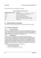
... (FWH) includes an 8 Mbit (1024 KB) symmetrical flash memory device. 7.4 Resource Configuration 7.4.1 PCI Autoconfiguration The BIOS can override the auto-configuration options by the add-in card. 7.4.2 PCI IDE Support If you select Auto in cards. System BIOS Intel® Entry Server Board SE7221BA1-E TPS Table 25 lists the function keys available for...
... (FWH) includes an 8 Mbit (1024 KB) symmetrical flash memory device. 7.4 Resource Configuration 7.4.1 PCI Autoconfiguration The BIOS can override the auto-configuration options by the add-in card. 7.4.2 PCI IDE Support If you select Auto in cards. System BIOS Intel® Entry Server Board SE7221BA1-E TPS Table 25 lists the function keys available for...


