
Product Guide
Page 1
Intel® Server Board SCB2 Product Guide A Guide for Technically Qualified Assemblers of Intel® Identified Subassemblies/Products Order Number: A55880-003
Intel® Server Board SCB2 Product Guide A Guide for Technically Qualified Assemblers of Intel® Identified Subassemblies/Products Order Number: A55880-003

Product Guide
Page 3
Contents 1 Description Server Board Features ...7 Server Board Connector and Component Locations 8 Back Panel Connectors 9 Processor ...10 Memory ...10 PCI Riser Slots ...10 Video ...11 SCSI Controller ...11 ATA-100 ... ACPI...16 Security ...17 Intrusion Switch Monitoring 17 Software Locks ...17 2 Installation Procedures Install the I/O Shield ...21 Rearrange the Standoffs ...22 Server Board Bumpers ...23 Install the Server Board ...24 Installing Processors ...25 Install the Processor Terminator 28 Memory ...29 Connect Cables...30 3 Upgrading Tools and Supplies Needed 31 Cautions ...31 ...
Contents 1 Description Server Board Features ...7 Server Board Connector and Component Locations 8 Back Panel Connectors 9 Processor ...10 Memory ...10 PCI Riser Slots ...10 Video ...11 SCSI Controller ...11 ATA-100 ... ACPI...16 Security ...17 Intrusion Switch Monitoring 17 Software Locks ...17 2 Installation Procedures Install the I/O Shield ...21 Rearrange the Standoffs ...22 Server Board Bumpers ...23 Install the Server Board ...24 Installing Processors ...25 Install the Processor Terminator 28 Memory ...29 Connect Cables...30 3 Upgrading Tools and Supplies Needed 31 Cautions ...31 ...
Product Guide
Page 4
... ...43 Record BIOS Setup Settings 44 If BIOS Setup Is Inaccessible 44 BIOS Setup Menus...44 Main Menu...45 Advanced Menu...46 Security Menu...49 Server Menu ...50 Boot Menu ...52 Exit Menu ...53 Temporarily Changing the Boot Device Priority 53 Permanently Changing the Boot Device Priority 54 Running the Adaptec... Preparation ...75 Extraction ...76 Updating ...76 Individual Updates...77 BIOS Upgrade Description 77 Firmware Update Utility Description 79 FRU/SDR Load Utility Description 79 iv Intel Server Board SCB2 Product Guide
... ...43 Record BIOS Setup Settings 44 If BIOS Setup Is Inaccessible 44 BIOS Setup Menus...44 Main Menu...45 Advanced Menu...46 Security Menu...49 Server Menu ...50 Boot Menu ...52 Exit Menu ...53 Temporarily Changing the Boot Device Priority 53 Permanently Changing the Boot Device Priority 54 Running the Adaptec... Preparation ...75 Extraction ...76 Updating ...76 Individual Updates...77 BIOS Upgrade Description 77 Firmware Update Utility Description 79 FRU/SDR Load Utility Description 79 iv Intel Server Board SCB2 Product Guide

Product Guide
Page 5
... Problems with Network 89 Problems with Application Software 90 Bootable CD-ROM Is Not Detected 90 6 Technical Reference Server Board Jumpers...91 Diagnostic LEDs...92 7 Regulatory and Integration Information Product Regulatory Compliance 97 Product Safety Compliance 97 Product EMC Compliance 97 Product Regulatory Compliance Markings ...
... Problems with Network 89 Problems with Application Software 90 Bootable CD-ROM Is Not Detected 90 6 Technical Reference Server Board Jumpers...91 Diagnostic LEDs...92 7 Regulatory and Integration Information Product Regulatory Compliance 97 Product Safety Compliance 97 Product EMC Compliance 97 Product Regulatory Compliance Markings ...

Product Guide
Page 6
... 9. Installing the Processor Terminator 28 15. Installing the Heat Sink 35 20. Jumper Locations ...91 Tables 1. Server Board Versions...7 2. Rear COM2 Port Adapter Pin-out 15 4. BIOS Setup Menu Navigation 44 8. Power Usage Worksheet 2 103 vi Intel Server Board SCB2 Product Guide Back Panel Connectors 9 3. Insert the Processor and Lower the Locking Bar 34 19. Replacing...
... 9. Installing the Processor Terminator 28 15. Installing the Heat Sink 35 20. Jumper Locations ...91 Tables 1. Server Board Versions...7 2. Rear COM2 Port Adapter Pin-out 15 4. BIOS Setup Menu Navigation 44 8. Power Usage Worksheet 2 103 vi Intel Server Board SCB2 Product Guide Back Panel Connectors 9 3. Insert the Processor and Lower the Locking Bar 34 19. Replacing...
Product Guide
Page 7
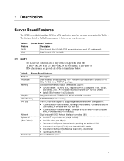
... chassis. Table 1. A 1U chassis requires low-profile (LP) 1.2-inch DIMMs. Graphics • Up to both server board versions. Table 2. 1 Description Server Board Features The SCB2 is available in either of the following configurations: • 1U configuration-one full-length, full-height 64-bit/66... package. The features listed in Table 2 are common to 6 GB of the features listed below. Server Board Features Feature Description Processors Dual processor slots supporting Intel® Pentium® III processors in Table 2 only reflects usage with either the 1U...
... chassis. Table 1. A 1U chassis requires low-profile (LP) 1.2-inch DIMMs. Graphics • Up to both server board versions. Table 2. 1 Description Server Board Features The SCB2 is available in either of the following configurations: • 1U configuration-one full-length, full-height 64-bit/66... package. The features listed in Table 2 are common to 6 GB of the features listed below. Server Board Features Feature Description Processors Dual processor slots supporting Intel® Pentium® III processors in Table 2 only reflects usage with either the 1U...

Product Guide
Page 8
...Figure 1. Figure 1 is a composite view of both SCSI and ATA versions. ID LED S. Fan module connector F. DIMM slots W. Alternate front panel connector J. Server Board Connector and Component Locations 8 Intel Server Board SCB2 Product Guide A BC D E F GH I /O ports X. Sys fan 1 connector C. ATA/IDE connector K. 66 MHz/64-bit PCI riser slot (...only) P. Primary processor socket GG. Battery T. Floppy drive connector E. 66 MHz/64-bit PCI riser slot (full height) V. Server Board Connector and Component Locations The SCB2 comes in both versions.
...Figure 1. Figure 1 is a composite view of both SCSI and ATA versions. ID LED S. Fan module connector F. DIMM slots W. Alternate front panel connector J. Server Board Connector and Component Locations 8 Intel Server Board SCB2 Product Guide A BC D E F GH I /O ports X. Sys fan 1 connector C. ATA/IDE connector K. 66 MHz/64-bit PCI riser slot (...only) P. Primary processor socket GG. Battery T. Floppy drive connector E. 66 MHz/64-bit PCI riser slot (full height) V. Server Board Connector and Component Locations The SCB2 comes in both versions.

Product Guide
Page 9
Back Panel Connectors A B C JK L D E F H I . SCSI connector (SCSI server board only) D. NIC 1 RJ-45 connector H. Green Status LED F. PS/2 keyboard/mouse connector K. USB 2 connector Figure 2. Video connector C. NIC 2 RJ-45 connector E. Yellow Status LED J. RJ-45 serial port L. Green Status LED I G OM11713 A. Back Panel Connectors Description 9 USB 1 connector B. Yellow Status LED G.
Back Panel Connectors A B C JK L D E F H I . SCSI connector (SCSI server board only) D. NIC 1 RJ-45 connector H. Green Status LED F. PS/2 keyboard/mouse connector K. USB 2 connector Figure 2. Video connector C. NIC 2 RJ-45 connector E. Yellow Status LED J. RJ-45 serial port L. Green Status LED I G OM11713 A. Back Panel Connectors Description 9 USB 1 connector B. Yellow Status LED G.
Product Guide
Page 10
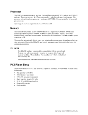
... PCI riser cards. This processor uses the .13 micron technology and offers advanced performance. Check the Intel Customer Support website for the latest tested memory list: http://support.intel.com/support/motherboards/server/scb2 PCI Riser Slots The server board has two PCI riser slots, each supporting 72-bit ECC (64-bit main memory plus ECC) registered...
... PCI riser cards. This processor uses the .13 micron technology and offers advanced performance. Check the Intel Customer Support website for the latest tested memory list: http://support.intel.com/support/motherboards/server/scb2 PCI Riser Slots The server board has two PCI riser slots, each supporting 72-bit ECC (64-bit main memory plus ECC) registered...

Product Guide
Page 11
... do not have a termination source provided. In a RAID configuration, multiple IDE hard drives are terminated through a jumper or resistor pack on the server board with active terminators that share a single 32-bit, 33-MHz PCI bus master interface as an independent disk, though the array may include one or...more arrays of video SDRAM that supports all standard IBM† VGA modes. Each array is terminated on the device itself. Video The SCB2 uses an ATI RAGE XL PCI graphics accelerator with PCI Local Bus Specification Revision 2.2 IDE RAID The ATA-100 controller supports IDE RAID ...
... do not have a termination source provided. In a RAID configuration, multiple IDE hard drives are terminated through a jumper or resistor pack on the server board with active terminators that share a single 32-bit, 33-MHz PCI bus master interface as an independent disk, though the array may include one or...more arrays of video SDRAM that supports all standard IBM† VGA modes. Each array is terminated on the device itself. Video The SCB2 uses an ATI RAGE XL PCI graphics accelerator with PCI Local Bus Specification Revision 2.2 IDE RAID The ATA-100 controller supports IDE RAID ...

Product Guide
Page 12
...EMC product regulation compliance, the system must be added and teamed to NIC 2. 12 Intel Server Board SCB2 Product Guide The yellow LED indicates 100-Mbps operation when lit. The server board uses two Intel® 82550PM Fast Ethernet† Controllers and supports two 10Base-T/100Base-TX network subsystems...of its drives. or 100-Mbps operation. With 4 drives attached to a secondary drive. To support both network teaming features and server management features, a third NIC must be used for storage capacity and data redundancy. RAID 1 configurations are used as it doubles ...
...EMC product regulation compliance, the system must be added and teamed to NIC 2. 12 Intel Server Board SCB2 Product Guide The yellow LED indicates 100-Mbps operation when lit. The server board uses two Intel® 82550PM Fast Ethernet† Controllers and supports two 10Base-T/100Base-TX network subsystems...of its drives. or 100-Mbps operation. With 4 drives attached to a secondary drive. To support both network teaming features and server management features, a third NIC must be used for storage capacity and data redundancy. RAID 1 configurations are used as it doubles ...

Product Guide
Page 13
... any hub or switch. • Adaptive Load Balancing (ALB) - creates a team of up an option, read the instructions in case of server connections. Adapter Fault Tolerance Adapter Fault Tolerance (AFT) is replaced, it will take over . AFT gives you can support teaming options and VLANs on...the backup will attempt to being the primary adapter in any 10Base-TX or 100Base-TX switch. • Fast EtherChannel† (FEC) or Intel® Link Aggregation - General Configuration Notes 1. NetWare can specify one as the secondary, you to increase the reliability of a cable, port,...
... any hub or switch. • Adaptive Load Balancing (ALB) - creates a team of up an option, read the instructions in case of server connections. Adapter Fault Tolerance Adapter Fault Tolerance (AFT) is replaced, it will take over . AFT gives you can support teaming options and VLANs on...the backup will attempt to being the primary adapter in any 10Base-TX or 100Base-TX switch. • Fast EtherChannel† (FEC) or Intel® Link Aggregation - General Configuration Notes 1. NetWare can specify one as the secondary, you to increase the reliability of a cable, port,...

Product Guide
Page 14
...continuously analyzes loading on each adapter and balances network traffic across the adapters as you add adapters to your server, you must have 2, 4, or 8 server adapters installed in teams to provide an increased transmit rate (up to which typically support RJ45 serial connectors.... efficient way to 8 Gbps) using a maximum of eight adapters. Adapter teams configured for serial concentrators, which standard is desired. 14 Intel Server Board SCB2 Product Guide The 8 pins of the RJ45 connector can be configured to the same network switch. To use a serial concentrator to the...
...continuously analyzes loading on each adapter and balances network traffic across the adapters as you add adapters to your server, you must have 2, 4, or 8 server adapters installed in teams to provide an increased transmit rate (up to which typically support RJ45 serial connectors.... efficient way to 8 Gbps) using a maximum of eight adapters. Adapter teams configured for serial concentrators, which standard is desired. 14 Intel Server Board SCB2 Product Guide The 8 pins of the RJ45 connector can be configured to the same network switch. To use a serial concentrator to the...

Product Guide
Page 15
...signal, the J6A2 jumper block must be configured as follows: The DCD jumper in position 2 and 3 and the DSR jumper in the factory, the SCB2 baseboard will have the rear RJ45 serial port configured to the jumper block. Table 3. For serial concentrators that require a DB9 type of this configuration. ...by an arrow directly next to -DB9 adapter must be configured as configured in position 2 and 3. J6A2 Jumper Block for DSR Signal For those server applications that require a DCD signal, the J6A2 jumper block must be used. Pin 1 on the jumper is denoted by an arrow directly next to...
...signal, the J6A2 jumper block must be configured as follows: The DCD jumper in position 2 and 3 and the DSR jumper in the factory, the SCB2 baseboard will have the rear RJ45 serial port configured to the jumper block. Table 3. For serial concentrators that require a DB9 type of this configuration. ...by an arrow directly next to -DB9 adapter must be configured as configured in position 2 and 3. J6A2 Jumper Block for DSR Signal For those server applications that require a DCD signal, the J6A2 jumper block must be used. Pin 1 on the jumper is denoted by an arrow directly next to...

Product Guide
Page 16
... as it was off. • s5: Soft off only when the AC power cord is disconnected. 16 Intel Server Board SCB2 Product Guide An ACPI aware operating system can also be used with both RJ45 ports are saved to disk. ...s4: Hibernate or Save to Disk: The memory and machine state are different. The SCB2 supports sleep states s0, s1, s4, and s5: • s0: Normal running in Figure 3. In this state. ...ACPI The SCB2 supports the Advanced Configuration and Power Interface (ACPI) as the pinout for the rear port cannot be...
... as it was off. • s5: Soft off only when the AC power cord is disconnected. 16 Intel Server Board SCB2 Product Guide An ACPI aware operating system can also be used with both RJ45 ports are saved to disk. ...s4: Hibernate or Save to Disk: The memory and machine state are different. The SCB2 supports sleep states s0, s1, s4, and s5: • s0: Normal running in Figure 3. In this state. ...ACPI The SCB2 supports the Advanced Configuration and Power Interface (ACPI) as the pinout for the rear port cannot be...

Product Guide
Page 17
...BIOS Setup or the SSU. • Must enter the supervisor password to boot the server if Password on Boot is set , you will transmit an alarm signal to the server board, where BMC firmware and server management software process the signal. Description 17 Once the security measures are set . ...; Set and enable a user password. • Set secure mode to prevent keyboard or mouse input and to prevent use of the server, Intel® Server Control server management software monitors the chassis intrusion switch if one is enabled in either the BIOS Setup or SSU. • Must enter the user...
...BIOS Setup or the SSU. • Must enter the supervisor password to boot the server if Password on Boot is set , you will transmit an alarm signal to the server board, where BMC firmware and server management software process the signal. Description 17 Once the security measures are set . ...; Set and enable a user password. • Set secure mode to prevent keyboard or mouse input and to prevent use of the server, Intel® Server Control server management software monitors the chassis intrusion switch if one is enabled in either the BIOS Setup or SSU. • Must enter the user...

Product Guide
Page 18
...have access to all of the options. • May enter either password to exit secure mode. continued 18 Intel Server Board SCB2 Product Guide To write protect access to diskette whether the server is in either the BIOS Setup or SSU. • May enter either password to boot the...Features Feature Description Secure mode How to enter secure mode: • Setting and enabling passwords automatically places the system in drive A, the server boots from drive C and automatically goes into effect at boot time. If there is no effect on Boot is entered. Disable writing to...
...have access to all of the options. • May enter either password to exit secure mode. continued 18 Intel Server Board SCB2 Product Guide To write protect access to diskette whether the server is in either the BIOS Setup or SSU. • May enter either password to boot the...Features Feature Description Secure mode How to enter secure mode: • Setting and enabling passwords automatically places the system in drive A, the server boots from drive C and automatically goes into effect at boot time. If there is no effect on Boot is entered. Disable writing to...

Product Guide
Page 19
... the system configuration, set ), then you specify in the Security Subsystem Group. If no keyboard or mouse action occurs for a password before the server fully boots. To disable a password, change the Clear Password jumper (see Chapter 5). Description 19 If secure mode is enabled (a user password is... minutes. The system can be accepted. If secure mode is enabled and the "Secure Boot Mode" option is also enabled, the server will fully boot but only the supervisor password will not be inhibited Specify and enable an inactivity time out period of the User Password...
... the system configuration, set ), then you specify in the Security Subsystem Group. If no keyboard or mouse action occurs for a password before the server fully boots. To disable a password, change the Clear Password jumper (see Chapter 5). Description 19 If secure mode is enabled (a user password is... minutes. The system can be accepted. If secure mode is enabled and the "Secure Boot Mode" option is also enabled, the server will fully boot but only the supervisor password will not be inhibited Specify and enable an inactivity time out period of the User Password...

Product Guide
Page 21
... the dotted groove is outside the chassis wall, and the lip of a chassis. Hold the shield in the back of the shield rests on the server board. 2 Installation Procedures Install the I/O Shield ✏ NOTE An ATX 2.03-compliant I/O shield is provided with the corresponding I/O connectors on the inner chassis wall. 3. The I /O ports... does not fit the chassis, obtain a properly sized shield from inside of the USB 2 connector. The shield has cutouts that the cutouts align with the server board.
... the dotted groove is outside the chassis wall, and the lip of a chassis. Hold the shield in the back of the shield rests on the server board. 2 Installation Procedures Install the I/O Shield ✏ NOTE An ATX 2.03-compliant I/O shield is provided with the corresponding I/O connectors on the inner chassis wall. 3. The I /O ports... does not fit the chassis, obtain a properly sized shield from inside of the USB 2 connector. The shield has cutouts that the cutouts align with the server board.

Product Guide
Page 22
Failure to properly rearrange the metal standoffs may cause the server board to malfunction and may be different from the illustration. = Figure 6. Rearrange the Standoffs If your chassis does not have board mount standoffs placed as shown, you must rearrange them so they match the holes in the server board. Rearrange the Standoffs OM11716B 22 Intel Server Board SCB2 Product Guide Your chassis may permanently damage it.
Failure to properly rearrange the metal standoffs may cause the server board to malfunction and may be different from the illustration. = Figure 6. Rearrange the Standoffs If your chassis does not have board mount standoffs placed as shown, you must rearrange them so they match the holes in the server board. Rearrange the Standoffs OM11716B 22 Intel Server Board SCB2 Product Guide Your chassis may permanently damage it.


