
Product Guide
Page 1
Intel® Server Board S845WD1-E (S845WD1H) Product Guide A Guide for Technically Qualified Assemblers of Intel® Identified Subassemblies/Products Order Number: C22229-001
Intel® Server Board S845WD1-E (S845WD1H) Product Guide A Guide for Technically Qualified Assemblers of Intel® Identified Subassemblies/Products Order Number: C22229-001

Product Guide
Page 3
... ...9 Back Panel Connectors 10 Front Panel Connectors 11 Server Board Connector and Component Locations 12 Processors...13 Memory 13 Intel 845E Chipset ...14 Intel 82845E Memory Controller Hub (MCH 14 Intel 82801BA I/O Controller Hub (ICH2 15 Intel 82802AB Firmware Hub (FWH 15 I/O Controller ...15 Serial Ports 16... Boot Options...22 CD-ROM and Network Boot 22 Booting Without Attached Devices 23 Fast Booting Systems with Intel® Rapid BIOS Boot 23 Intel Rapid BIOS Boot 23 BIOS Security Passwords 24 System Management BIOS (SMBIOS 25 Power Management Features 25 Wake...
... ...9 Back Panel Connectors 10 Front Panel Connectors 11 Server Board Connector and Component Locations 12 Processors...13 Memory 13 Intel 845E Chipset ...14 Intel 82845E Memory Controller Hub (MCH 14 Intel 82801BA I/O Controller Hub (ICH2 15 Intel 82802AB Firmware Hub (FWH 15 I/O Controller ...15 Serial Ports 16... Boot Options...22 CD-ROM and Network Boot 22 Booting Without Attached Devices 23 Fast Booting Systems with Intel® Rapid BIOS Boot 23 Intel Rapid BIOS Boot 23 BIOS Security Passwords 24 System Management BIOS (SMBIOS 25 Power Management Features 25 Wake...

Product Guide
Page 4
...Cautions ...37 Memory ...38 DIMM Installation Guidelines 38 Installing DIMMs ...39 Removing DIMMs ...40 Installing the I/O Shield...41 Installing the Server Board 42 Installing a Processor ...43 Removing the Processor ...45 Replacing the Battery ...46 Connecting the IDE Cable 49 Setting the BIOS Configuration... the Intel® Express BIOS Update Utility 51 Updating the BIOS with the Intel® Flash Memory Update Utility 51 Preparing for the Update 51 Obtaining the BIOS Update File 52 Recording the Current BIOS Settings 52 Creating Bootable Media 52 iv Intel Server Board S845WD1-E (...
...Cautions ...37 Memory ...38 DIMM Installation Guidelines 38 Installing DIMMs ...39 Removing DIMMs ...40 Installing the I/O Shield...41 Installing the Server Board 42 Installing a Processor ...43 Removing the Processor ...45 Replacing the Battery ...46 Connecting the IDE Cable 49 Setting the BIOS Configuration... the Intel® Express BIOS Update Utility 51 Updating the BIOS with the Intel® Flash Memory Update Utility 51 Preparing for the Update 51 Obtaining the BIOS Update File 52 Recording the Current BIOS Settings 52 Creating Bootable Media 52 iv Intel Server Board S845WD1-E (...
Product Guide
Page 5
... BIOS Error Messages...78 5 Getting Help 81 World Wide Web ...81 Telephone ...81 6 Technical Reference 83 Server Board Connectors 83 Baseboard Connectors 84 Power and Hardware Control Connectors 84 Add-In Board and Peripheral Interface Connectors 85 Server Board Resources ...86 Memory Map...86 DMA Channels...86 I/O Map 87 Interrupts ...88 7 Regulatory and Integration Information...
... BIOS Error Messages...78 5 Getting Help 81 World Wide Web ...81 Telephone ...81 6 Technical Reference 83 Server Board Connectors 83 Baseboard Connectors 84 Power and Hardware Control Connectors 84 Add-In Board and Peripheral Interface Connectors 85 Server Board Resources ...86 Memory Map...86 DMA Channels...86 I/O Map 87 Interrupts ...88 7 Regulatory and Integration Information...

Product Guide
Page 6
...45 Figure 12. Table 5. Table 11. Back Panel Connectors 10 Figure 2. DIMM Socket Locations 39 Figure 6. Removing the Battery 48 Figure 13. Server Board Features 9 Supported Processors 13 Supported Memory Configurations 13 Supervisor and User Password Functions 24 Effects of the Mounting Screw Holes 42 Figure 8. Connecting the ...Overload 95 Place Battery Marking 95 Use Only for the BIOS Setup Program Modes 50 BIOS Setup Program Menu Bar 56 vi Intel Server Board S845WD1-E (S845WD1H) Product Guide Attaching the Heat Sink to the Processor 43 Figure 10. Table 10.
...45 Figure 12. Table 5. Table 11. Back Panel Connectors 10 Figure 2. DIMM Socket Locations 39 Figure 6. Removing the Battery 48 Figure 13. Server Board Features 9 Supported Processors 13 Supported Memory Configurations 13 Supervisor and User Password Functions 24 Effects of the Mounting Screw Holes 42 Figure 8. Connecting the ...Overload 95 Place Battery Marking 95 Use Only for the BIOS Setup Program Modes 50 BIOS Setup Program Menu Bar 56 vi Intel Server Board S845WD1-E (S845WD1H) Product Guide Attaching the Heat Sink to the Processor 43 Figure 10. Table 10.
Product Guide
Page 9
... BIOS with three PCI connectors and four embedded devices: • 2D/3D graphics controller - Server Board Features Feature Processors Description Support for an Intel® Pentium® 4 processor in a µPGA478 socket Support for an Intel® Celeron® processor in a µPGA478 socket 400/533 MHz Supported Memory • Two 184-pin DDR...
... BIOS with three PCI connectors and four embedded devices: • 2D/3D graphics controller - Server Board Features Feature Processors Description Support for an Intel® Pentium® 4 processor in a µPGA478 socket Support for an Intel® Celeron® processor in a µPGA478 socket 400/533 MHz Supported Memory • Two 184-pin DDR...

Product Guide
Page 10
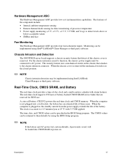
PS/2 keyboard C. USB port 1 H. USB port 2 I A. Parallel port D. Serial port A E. PS/2 mouse B. A C F B D E GH I . Back Panel Connectors OM14342 10 Intel Server Board S845WD1-E (S845WD1H) Product Guide NIC 1 G. Video port F. Back Panel Connectors The back panel connectors are color-coded in compliance with PC 99 recommendations. NIC 2 Figure 1.
PS/2 keyboard C. USB port 1 H. USB port 2 I A. Parallel port D. Serial port A E. PS/2 mouse B. A C F B D E GH I . Back Panel Connectors OM14342 10 Intel Server Board S845WD1-E (S845WD1H) Product Guide NIC 1 G. Video port F. Back Panel Connectors The back panel connectors are color-coded in compliance with PC 99 recommendations. NIC 2 Figure 1.

Product Guide
Page 13
... Support website for DDR SDRAM density and DDR SDRAM organization. Description 13 Processors The S845WD1H board supports a single Intel Pentium 4 processor with the server board and must be supported in a 1U server chassis. DIMM Capacity 64 MB 64 MB 128 MB 128 MB 128 MB 256 MB 256 MB 256 MB 512 MB 512 MB... devices is a 2 GB stacked un-buffered DDR200/266 ECC DIMM. Front side population/back side population indicated for the latest tested memory list: http://support.intel.com/support/motherboards/server/S845WD1-E Table 3.
... Support website for DDR SDRAM density and DDR SDRAM organization. Description 13 Processors The S845WD1H board supports a single Intel Pentium 4 processor with the server board and must be supported in a 1U server chassis. DIMM Capacity 64 MB 64 MB 128 MB 128 MB 128 MB 256 MB 256 MB 256 MB 512 MB 512 MB... devices is a 2 GB stacked un-buffered DDR200/266 ECC DIMM. Front side population/back side population indicated for the latest tested memory list: http://support.intel.com/support/motherboards/server/S845WD1-E Table 3.

Product Guide
Page 14
...Firmware Hub (FWH) The MCH is driving the processor data bus, although the data bus ECC can be supported on the S845WD1H server board. Intel 82845E Memory Controller Hub (MCH) The MCH supports the data integrity features supported by BIOS. The MCH provides the following: &#...; 2.5 V (only) 184-pin DDR SDRAM DIMMs with auto detection of SDRAM. • Support for ACPI Rev 1.0b compliant power management. 14 Intel Server Board S845WD1-E (S845WD1H) Product Guide The FWH provides the nonvolatile storage of the BIOS. DIMM and memory configurations must adhere to RAM • Non-ECC and...
...Firmware Hub (FWH) The MCH is driving the processor data bus, although the data bus ECC can be supported on the S845WD1H server board. Intel 82845E Memory Controller Hub (MCH) The MCH supports the data integrity features supported by BIOS. The MCH provides the following: &#...; 2.5 V (only) 184-pin DDR SDRAM DIMMs with auto detection of SDRAM. • Support for ACPI Rev 1.0b compliant power management. 14 Intel Server Board S845WD1-E (S845WD1H) Product Guide The FWH provides the nonvolatile storage of the BIOS. DIMM and memory configurations must adhere to RAM • Non-ECC and...

Product Guide
Page 16
Serial Ports The S845WD1H server board has one serial port connector and one serial port header. The +5 V lines to 115.2 kb/s with a PolySwitch† circuit that are compatible with the Wired... The serial port A connector is connected or disconnected. Hardware Management Subsystem The Hardware Management features enable the board to the following : • Fan monitoring • Thermal and voltage monitoring • Chassis intrusion detection 16 Intel Server Board S845WD1-E (S845WD1H) Product Guide In the BIOS Setup program, the parallel port can be compatible with the 82077...
Serial Ports The S845WD1H server board has one serial port connector and one serial port header. The +5 V lines to 115.2 kb/s with a PolySwitch† circuit that are compatible with the Wired... The serial port A connector is connected or disconnected. Hardware Management Subsystem The Hardware Management features enable the board to the following : • Fan monitoring • Thermal and voltage monitoring • Chassis intrusion detection 16 Intel Server Board S845WD1-E (S845WD1H) Product Guide In the BIOS Setup program, the parallel port can be compatible with the 82077...
Product Guide
Page 17
...supply extends the life of processor temperature • Power supply monitoring (+5 V, +3.3 V, +1.5 V, 3.3 VSB, and Vccp) to their defaults by using Intel LANDesk Client Manager or third-party software. The security feature uses a mechanical switch on . A coin-cell battery (CR2032) powers the real-time clock ...minutes/year at power-on the chassis that are reserved for direct monitoring of the battery. Chassis Intrusion and Detection The S845WD1H server board supports a chassis security feature that detects if the chassis cover is accurate to AC power. When the chassis cover is ...
...supply extends the life of processor temperature • Power supply monitoring (+5 V, +3.3 V, +1.5 V, 3.3 VSB, and Vccp) to their defaults by using Intel LANDesk Client Manager or third-party software. The security feature uses a mechanical switch on . A coin-cell battery (CR2032) powers the real-time clock ...minutes/year at power-on the chassis that are reserved for direct monitoring of the battery. Chassis Intrusion and Detection The S845WD1H server board supports a chassis security feature that detects if the chassis cover is accurate to AC power. When the chassis cover is ...

Product Guide
Page 18
... supports UHCI and uses UHCI-compatible software drivers. ✏ NOTE Computer systems that Legacy USB support in legacy mode. 18 Intel Server Board S845WD1-E (S845WD1H) Product Guide When the user applies power to the computer, legacy support is attached to each port. POST completes. 5. To ... loads the USB drivers, all legacy and non-legacy USB devices are accessible via the front panel USB header. POST begins. 3. The S845WD1H server board has four USB 1.1 ports; Legacy USB Support Legacy USB support enables USB devices such as follows: 1. Legacy USB support is enabled by the...
... supports UHCI and uses UHCI-compatible software drivers. ✏ NOTE Computer systems that Legacy USB support in legacy mode. 18 Intel Server Board S845WD1-E (S845WD1H) Product Guide When the user applies power to the computer, legacy support is attached to each port. POST completes. 5. To ... loads the USB drivers, all legacy and non-legacy USB devices are accessible via the front panel USB header. POST begins. 3. The S845WD1H server board has four USB 1.1 ports; Legacy USB Support Legacy USB support enables USB devices such as follows: 1. Legacy USB support is enabled by the...
Product Guide
Page 19
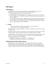
The BIOS supports Logical Block Addressing (LBA) and Extended Cylinder Head Sector (ECHS) translation modes. The S845WD1H server board supports Laser Servo (LS-120) diskette technology through the IDE interfaces. Description 19 The IDE interfaces also support ATAPI devices (such as the onboard IDE ...
The BIOS supports Logical Block Addressing (LBA) and Extended Cylinder Head Sector (ECHS) translation modes. The S845WD1H server board supports Laser Servo (LS-120) diskette technology through the IDE interfaces. Description 19 The IDE interfaces also support ATAPI devices (such as the onboard IDE ...

Product Guide
Page 20
...The BIOS determines the capabilities of each drive and configures them to configure the system. BIOS The S845WD1H server board uses an Intel/AMI BIOS that of the slowest device. 20 Intel Server Board S845WD1-E (S845WD1H) Product Guide The FWH contains the BIOS Setup program, POST, the PCI auto-configuration utility...✏ NOTE ATA-66/100 compatible cables are automatically configured for use by specifying manual configuration in cards. The S845WD1H server board supports system BIOS shadowing, allowing the BIOS to be onboard or add-in the BIOS Setup program. The IDE interface ...
...The BIOS determines the capabilities of each drive and configures them to configure the system. BIOS The S845WD1H server board uses an Intel/AMI BIOS that of the slowest device. 20 Intel Server Board S845WD1-E (S845WD1H) Product Guide The FWH contains the BIOS Setup program, POST, the PCI auto-configuration utility...✏ NOTE ATA-66/100 compatible cables are automatically configured for use by specifying manual configuration in cards. The S845WD1H server board supports system BIOS shadowing, allowing the BIOS to be onboard or add-in the BIOS Setup program. The IDE interface ...

Product Guide
Page 22
... must be a standard 1.44 MB diskette not a 120 MB diskette. The fourth device is configured to it. This selection allows booting from the on-board NIC or a network add-in the Setup program's Removable Devices submenu), the BIOS recovery diskette must be selected as a boot device. The BIOS can... continuous beeps indicates a failed BIOS recovery. Boot devices are available from an LS-120 diskette (in card with a remote boot ROM installed. 22 Intel Server Board S845WD1-E (S845WD1H) Product Guide For example, the data can be created and the BIOS update files copied to boot from...
... must be a standard 1.44 MB diskette not a 120 MB diskette. The fourth device is configured to it. This selection allows booting from the on-board NIC or a network add-in the Setup program's Removable Devices submenu), the BIOS recovery diskette must be selected as a boot device. The BIOS can... continuous beeps indicates a failed BIOS recovery. Boot devices are available from an LS-120 diskette (in card with a remote boot ROM installed. 22 Intel Server Board S845WD1-E (S845WD1H) Product Guide For example, the data can be created and the BIOS update files copied to boot from...

Product Guide
Page 24
...; The supervisor password gives unrestricted access to Enter Setup None Supervisor User Supervisor or user Password During Boot None None User Supervisor or user 24 Intel Server Board S845WD1-E (S845WD1H) Product Guide The password prompt is displayed before the server is set, the server boots without asking for a password. If only the supervisor password is booted.
...; The supervisor password gives unrestricted access to Enter Setup None Supervisor User Supervisor or user Password During Boot None None User Supervisor or user 24 Intel Server Board S845WD1-E (S845WD1H) Product Guide The password prompt is displayed before the server is set, the server boots without asking for a password. If only the supervisor password is booted.
Product Guide
Page 26
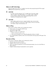
... to support multiple wake events from the ACPI S1. • Requires only one call to access the server: The first call powers up the server The second call similarly for correct operation. 26 Intel Server Board S845WD1-E (S845WD1H) Product Guide Wake on LAN Technology Network adapters that are PCI 2.2 compliant assert the wake-up...
... to support multiple wake events from the ACPI S1. • Requires only one call to access the server: The first call powers up the server The second call similarly for correct operation. 26 Intel Server Board S845WD1-E (S845WD1H) Product Guide Wake on LAN Technology Network adapters that are PCI 2.2 compliant assert the wake-up...
Product Guide
Page 27
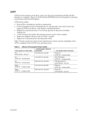
Soft off) Less than four seconds ...the system enters this state... Effects of individual devices, add-in boards (some add-in boards may require an ACPI-aware driver), video displays, and hard disk drives • Methods for achieving less than four seconds Sleep (ACPI...device enumeration) • Power management control of Pressing the Power Switch ...and the power switch is If the system is configured with the S845WD1H server board requires an operating system that enables the operating system to power-off ) Wake-up events (see Table 7, page29) • Support for Off...
Soft off) Less than four seconds ...the system enters this state... Effects of individual devices, add-in boards (some add-in boards may require an ACPI-aware driver), video displays, and hard disk drives • Methods for achieving less than four seconds Sleep (ACPI...device enumeration) • Power management control of Pressing the Power Switch ...and the power switch is If the system is configured with the S845WD1H server board requires an operating system that enables the operating system to power-off ) Wake-up events (see Table 7, page29) • Support for Off...
Product Guide
Page 28
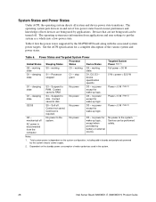
... or external source. See the ACPI specification for a complete description of how devices are not being used in the system. 28 Intel Server Board S845WD1-E (S845WD1H) Product Guide Power States and Targeted System Power Global States Sleeping States Processor States Device States Targeted System Power (Note ...working D0 - sleeping state G2/S5 S3 - S5 - no power except for wake-up logic, except when provided by the S845WD1H board along with the associated system power targets. Table 6. Cold boot is disconnected from applications and user settings to put the system as ...
... or external source. See the ACPI specification for a complete description of how devices are not being used in the system. 28 Intel Server Board S845WD1-E (S845WD1H) Product Guide Power States and Targeted System Power Global States Sleeping States Processor States Device States Targeted System Power (Note ...working D0 - sleeping state G2/S5 S3 - S5 - no power except for wake-up logic, except when provided by the S845WD1H board along with the associated system power targets. Table 6. Cold boot is disconnected from applications and user settings to put the system as ...
Product Guide
Page 29
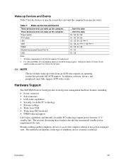
...; NOTE The use of telephony device (external or internal). In addition, software, drivers, and peripherals must fully support ACPI wake events. Hardware Support The S845WD1H server board provides several power management hardware features, including: • Power connector • Fan connectors • LAN wake capabilities • Instantly Available PC technology • Resume on...
...; NOTE The use of telephony device (external or internal). In addition, software, drivers, and peripherals must fully support ACPI wake events. Hardware Support The S845WD1H server board provides several power management hardware features, including: • Power connector • Fan connectors • LAN wake capabilities • Instantly Available PC technology • Resume on...


