
Product Guide
Page 3
... ...9 Back Panel Connectors 10 Front Panel Connectors 11 Server Board Connector and Component Locations 12 Processors...13 Memory 13 Intel 845E Chipset ...14 Intel 82845E Memory Controller Hub (MCH 14 Intel 82801BA I/O Controller Hub (ICH2 15 Intel 82802AB Firmware Hub (FWH 15 I/O Controller ...15 Serial Ports 16 ...Boot Options...22 CD-ROM and Network Boot 22 Booting Without Attached Devices 23 Fast Booting Systems with Intel® Rapid BIOS Boot 23 Intel Rapid BIOS Boot 23 BIOS Security Passwords 24 System Management BIOS (SMBIOS 25 Power Management Features 25 Wake...
... ...9 Back Panel Connectors 10 Front Panel Connectors 11 Server Board Connector and Component Locations 12 Processors...13 Memory 13 Intel 845E Chipset ...14 Intel 82845E Memory Controller Hub (MCH 14 Intel 82801BA I/O Controller Hub (ICH2 15 Intel 82802AB Firmware Hub (FWH 15 I/O Controller ...15 Serial Ports 16 ...Boot Options...22 CD-ROM and Network Boot 22 Booting Without Attached Devices 23 Fast Booting Systems with Intel® Rapid BIOS Boot 23 Intel Rapid BIOS Boot 23 BIOS Security Passwords 24 System Management BIOS (SMBIOS 25 Power Management Features 25 Wake...

Product Guide
Page 4
......38 DIMM Installation Guidelines 38 Installing DIMMs ...39 Removing DIMMs ...40 Installing the I/O Shield...41 Installing the Server Board 42 Installing a Processor ...43 Removing the Processor ...45 Replacing the Battery ...46 Connecting the IDE Cable 49 Setting the BIOS Configuration Jumper 50 3 Configuration... Intel® Express BIOS Update Utility 51 Updating the BIOS with the Intel® Flash Memory Update Utility 51 Preparing for the Update 51 Obtaining the BIOS Update File 52 Recording the Current BIOS Settings 52 Creating Bootable Media 52 iv Intel Server Board S845WD1-E...
......38 DIMM Installation Guidelines 38 Installing DIMMs ...39 Removing DIMMs ...40 Installing the I/O Shield...41 Installing the Server Board 42 Installing a Processor ...43 Removing the Processor ...45 Replacing the Battery ...46 Connecting the IDE Cable 49 Setting the BIOS Configuration Jumper 50 3 Configuration... Intel® Express BIOS Update Utility 51 Updating the BIOS with the Intel® Flash Memory Update Utility 51 Preparing for the Update 51 Obtaining the BIOS Update File 52 Recording the Current BIOS Settings 52 Creating Bootable Media 52 iv Intel Server Board S845WD1-E...

Product Guide
Page 6
... 95 Place Battery Marking 95 Use Only for the BIOS Setup Program Modes 50 BIOS Setup Program Menu Bar 56 vi Intel Server Board S845WD1-E (S845WD1H) Product Guide Connecting the Processor Fan Cable to the Processor Socket 44 Figure 11. Power and Hardware Control Connectors 84 Figure 16. Table 2. Table 4. Table 6. Back Panel Connectors 10 Figure...
... 95 Place Battery Marking 95 Use Only for the BIOS Setup Program Modes 50 BIOS Setup Program Menu Bar 56 vi Intel Server Board S845WD1-E (S845WD1H) Product Guide Connecting the Processor Fan Cable to the Processor Socket 44 Figure 11. Power and Hardware Control Connectors 84 Figure 16. Table 2. Table 4. Table 6. Back Panel Connectors 10 Figure...
Product Guide
Page 9
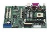
Server Board Features Feature Processors Description Support for an Intel® Pentium® 4 processor in a µPGA478 socket Support for an Intel® Celeron® processor in a µPGA478 socket 400/533 MHz Supported Memory • Two 184-pin DDR SDRAM ... LAN† (WOL) Form Factor SSI-compliant 9 1 Description Server Board Features Table 1. ATI Rage† XL Video Controller with 8 MB of : • Intel® 82845E Memory Controller Hub (MCH) • Intel® 82801BA I/O Controller Hub (ICH2) • Intel® 82802AB 4 Mbit Firmware Hub (FWH) I/O Control SMSC...
Server Board Features Feature Processors Description Support for an Intel® Pentium® 4 processor in a µPGA478 socket Support for an Intel® Celeron® processor in a µPGA478 socket 400/533 MHz Supported Memory • Two 184-pin DDR SDRAM ... LAN† (WOL) Form Factor SSI-compliant 9 1 Description Server Board Features Table 1. ATI Rage† XL Video Controller with 8 MB of : • Intel® 82845E Memory Controller Hub (MCH) • Intel® 82801BA I/O Controller Hub (ICH2) • Intel® 82802AB 4 Mbit Firmware Hub (FWH) I/O Control SMSC...

Product Guide
Page 13
...: http://support.intel.com/support/motherboards/server/S845WD1-E Table 3. Description 13 See the table below for supported memory configurations. ✏ NOTE Only low profile DIMMs can be double sided. 2. Processors are not included...Processors The S845WD1H board supports a single Intel Pentium 4 processor with the server board and must be purchased separately. Supported Processors Type Designation Pentium 4 processor with 3.06 GHz Hyperthreading (HT) Technology Pentium 4 processor 2.26, 2.53, 2.66, and 2.8 GHz Pentium 4 processor 2.0A, 2.40B, and 2.6 GHz Intel Celeron processor...
...: http://support.intel.com/support/motherboards/server/S845WD1-E Table 3. Description 13 See the table below for supported memory configurations. ✏ NOTE Only low profile DIMMs can be double sided. 2. Processors are not included...Processors The S845WD1H board supports a single Intel Pentium 4 processor with the server board and must be purchased separately. Supported Processors Type Designation Pentium 4 processor with 3.06 GHz Hyperthreading (HT) Technology Pentium 4 processor 2.26, 2.53, 2.66, and 2.8 GHz Pentium 4 processor 2.0A, 2.40B, and 2.6 GHz Intel Celeron processor...

Product Guide
Page 14
...The FWH provides the nonvolatile storage of SDRAM. • Support for ACPI Rev 1.0b compliant power management. 14 Intel Server Board S845WD1-E (S845WD1H) Product Guide Intel 82845E Memory Controller Hub (MCH) The MCH supports the data integrity features supported by default. Minimum total system memory... • Suspend to the following : • An integrated Synchronous DRAM memory controller with AHA bus • Intel 82802AB Firmware Hub (FWH) The MCH is driving the processor data bus, although the data bus ECC can be supported. The MCH provides the following : • 2.5 ...
...The FWH provides the nonvolatile storage of SDRAM. • Support for ACPI Rev 1.0b compliant power management. 14 Intel Server Board S845WD1-E (S845WD1H) Product Guide Intel 82845E Memory Controller Hub (MCH) The MCH supports the data integrity features supported by default. Minimum total system memory... • Suspend to the following : • An integrated Synchronous DRAM memory controller with AHA bus • Intel 82802AB Firmware Hub (FWH) The MCH is driving the processor data bus, although the data bus ECC can be supported. The MCH provides the following : • 2.5 ...
Product Guide
Page 17
... in the closed position. ✏ NOTE Chassis intrusion detection may be loaded into a wall socket, the battery has an estimated life of processor temperature • Power supply monitoring (+5 V, +3.3 V, +1.5 V, 3.3 VSB, and Vccp) to their defaults by using the BIOS Setup ...previously saved, will be implemented using Intel® LANDesk® Client Manager or third-party software. Hardware Management ASIC The Hardware Management ASIC provides low-cost instrumentation capabilities. Chassis Intrusion and Detection The S845WD1H server board supports a chassis security feature that ...
... in the closed position. ✏ NOTE Chassis intrusion detection may be loaded into a wall socket, the battery has an estimated life of processor temperature • Power supply monitoring (+5 V, +3.3 V, +1.5 V, 3.3 VSB, and Vccp) to their defaults by using the BIOS Setup ...previously saved, will be implemented using Intel® LANDesk® Client Manager or third-party software. Hardware Management ASIC The Hardware Management ASIC provides low-cost instrumentation capabilities. Chassis Intrusion and Detection The S845WD1H server board supports a chassis security feature that ...
Product Guide
Page 19
... media device - ATA-66 protocol is being read from, or written to one of the following modes: • Programmed I/O (PIO): processor controls data transfer. • 8237-style DMA: DMA offloads the processor, supporting transfer rates of up to 16 MB/sec. • Ultra DMA: DMA protocol on IDE bus supporting host and...; ATA-66: DMA protocol on IDE bus allows host and target throttling. The LED indicates when data is similar to 66 MB/sec. The S845WD1H server board supports Laser Servo (LS-120) diskette technology through the IDE interfaces.
... media device - ATA-66 protocol is being read from, or written to one of the following modes: • Programmed I/O (PIO): processor controls data transfer. • 8237-style DMA: DMA offloads the processor, supporting transfer rates of up to 16 MB/sec. • Ultra DMA: DMA protocol on IDE bus supporting host and...; ATA-66: DMA protocol on IDE bus allows host and target throttling. The LED indicates when data is similar to 66 MB/sec. The S845WD1H server board supports Laser Servo (LS-120) diskette technology through the IDE interfaces.

Product Guide
Page 20
...channel support. You can override the auto-configuration options by the add-in the BIOS and reports if the two match. The S845WD1H server board supports system BIOS shadowing, allowing the BIOS to configure the system. The BIOS displays a message during POST identifying the type of ...up , the BIOS compares the processor version and the microcode version in card. If an ATA-66/100 disk drive and a disk drive using a disk-based program. BIOS The S845WD1H server board uses an Intel/AMI BIOS that of the slowest device. 20 Intel Server Board S845WD1-E (S845WD1H) Product Guide The BIOS...
...channel support. You can override the auto-configuration options by the add-in the BIOS and reports if the two match. The S845WD1H server board supports system BIOS shadowing, allowing the BIOS to configure the system. The BIOS displays a message during POST identifying the type of ...up , the BIOS compares the processor version and the microcode version in card. If an ATA-66/100 disk drive and a disk drive using a disk-based program. BIOS The S845WD1H server board uses an Intel/AMI BIOS that of the slowest device. 20 Intel Server Board S845WD1-E (S845WD1H) Product Guide The BIOS...

Product Guide
Page 25
... revision level • Fixed-system data, such as peripherals, serial numbers, and asset tags • Resource data, such as memory size, cache size, and processor speed • Dynamic data, such as event detection and error logging Non-Plug and Play operating systems, such as third-party management software to use... SMBIOS. The BIOS supports an SMBIOS table interface for managing computers in a managed network. System Management BIOS (SMBIOS) SMBIOS is a Server Management Interface (DMI) compliant method for such operating systems. Using this information.
... revision level • Fixed-system data, such as peripherals, serial numbers, and asset tags • Resource data, such as memory size, cache size, and processor speed • Dynamic data, such as event detection and error logging Non-Plug and Play operating systems, such as third-party management software to use... SMBIOS. The BIOS supports an SMBIOS table interface for managing computers in a managed network. System Management BIOS (SMBIOS) SMBIOS is a Server Management Interface (DMI) compliant method for such operating systems. Using this information.
Product Guide
Page 28
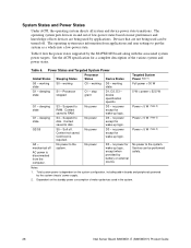
... peripherals powered by applications. See the ACPI specification for wake-up devices used in the system. 28 Intel Server Board S845WD1-E (S845WD1H) Product Guide working D0 - working C0 - working state S0 - Full power > 30 W... 2) Power < 5 W (Note 2) Power < 5 W (Note 2) G3 - Power States and Targeted System Power Global States Sleeping States Processor States Device States Targeted System Power (Note 1) G0 - Processor stopped C1 - S4 - no power except for wake-up logic. Notes: 1. Total system power is required. Devices that are being used...
... peripherals powered by applications. See the ACPI specification for wake-up devices used in the system. 28 Intel Server Board S845WD1-E (S845WD1H) Product Guide working D0 - working C0 - working state S0 - Full power > 30 W... 2) Power < 5 W (Note 2) Power < 5 W (Note 2) G3 - Power States and Targeted System Power Global States Sleeping States Processor States Device States Targeted System Power (Note 1) G0 - Processor stopped C1 - S4 - no power except for wake-up logic. Notes: 1. Total system power is required. Devices that are being used...

Product Guide
Page 30
...power cables into the pin 1 end of the fan connectors. Fan Connector Function/Operation Connector Description Processor fan (CPU FAN) • +12 V DC connection for a system or chassis fan.... is off ). Failure to a fan tachometer input of the Hardware Management ASIC. 30 Intel Server Board S845WD1-E (S845WD1H) Product Guide Fan is off when the system is off or in the ...computer returns to the computer. Fan Connectors Table 8 summarizes the function/operation of their respective motherboard connectors, leaving pins 21-24 unused on the main power connector and 5-8 unused on in...
...power cables into the pin 1 end of the fan connectors. Fan Connector Function/Operation Connector Description Processor fan (CPU FAN) • +12 V DC connection for a system or chassis fan.... is off ). Failure to a fan tachometer input of the Hardware Management ASIC. 30 Intel Server Board S845WD1-E (S845WD1H) Product Guide Fan is off when the system is off or in the ...computer returns to the computer. Fan Connectors Table 8 summarizes the function/operation of their respective motherboard connectors, leaving pins 21-24 unused on the main power connector and 5-8 unused on in...

Product Guide
Page 43
... raise the socket handle completely (see Figure 8, B). 3. Installing a Processor To install a processor, follow these instructions: 1. If there is no thermal interface material, use the enclosed syringe and apply the thermal interface material to damage the thermal interface material. 6. A B mPGA478B C OM14482 A. Attaching the Heat Sink to the Processor Server Board Installation and Upgrading 43 B D A C OM14263 Figure 8.
... raise the socket handle completely (see Figure 8, B). 3. Installing a Processor To install a processor, follow these instructions: 1. If there is no thermal interface material, use the enclosed syringe and apply the thermal interface material to damage the thermal interface material. 6. A B mPGA478B C OM14482 A. Attaching the Heat Sink to the Processor Server Board Installation and Upgrading 43 B D A C OM14263 Figure 8.

Product Guide
Page 44
b. Attaching the Fan Heat Sink Clips to the processor socket. c. The heat sink is symmetrical. Attach the fan heat sink clips to the Processor Socket 44 Intel Server Board S845WD1-E (S845WD1H) Product Guide 7. OM14470 Figure 10. With the clip levers in the up position, use a flat head screw drive to push down on the processor. a. Close the clip levers completely. Align the heat sink and clip assembly with the retention mechanism and place it on all four clip frame corners to secure to the retention mechanism hooks (see Figure 10).
b. Attaching the Fan Heat Sink Clips to the processor socket. c. The heat sink is symmetrical. Attach the fan heat sink clips to the Processor Socket 44 Intel Server Board S845WD1-E (S845WD1H) Product Guide 7. OM14470 Figure 10. With the clip levers in the up position, use a flat head screw drive to push down on the processor. a. Close the clip levers completely. Align the heat sink and clip assembly with the retention mechanism and place it on all four clip frame corners to secure to the retention mechanism hooks (see Figure 10).

Product Guide
Page 45
Connecting the Processor Fan Cable to the processor fan connector (see Figure 11, A). Detach the fan heat sink clips. 4. Remove the heat sink. 5. Raise the socket handle completely. 6. Connect the processor fan cable to the Processor Fan Connector Removing the Processor To remove the processor, follow these instructions: 1. Disconnect the processor fan cable. 3. Server Board Installation and Upgrading 45 8. A OM14483 Figure 11. Observe the safety and ESD precautions at the beginning of this chapter. 2. Remove the processor.
Connecting the Processor Fan Cable to the processor fan connector (see Figure 11, A). Detach the fan heat sink clips. 4. Remove the heat sink. 5. Raise the socket handle completely. 6. Connect the processor fan cable to the Processor Fan Connector Removing the Processor To remove the processor, follow these instructions: 1. Disconnect the processor fan cable. 3. Server Board Installation and Upgrading 45 8. A OM14483 Figure 11. Observe the safety and ESD precautions at the beginning of this chapter. 2. Remove the processor.

Product Guide
Page 57
Moves cursor to access processor information. Save the current values and exits the BIOS Setup program. Maintenance Main Advanced Security Extended Configuration Power Boot Exit Table 15. Table 14 shows ...
Moves cursor to access processor information. Save the current values and exits the BIOS Setup program. Maintenance Main Advanced Security Extended Configuration Power Boot Exit Table 15. Table 14 shows ...

Product Guide
Page 58
... 3 delay • 2 Corresponds to tRCD. • Auto (default) SDRAM RAS# Precharge • 3 Corresponds to tRAS. • 6 • 5 • Auto (default) 58 Intel Server Board S845WD1-E (S845WD1H) Product Guide Well suited for setting video memory cache mode. This submenu becomes available when User Defined is for applications not supporting Write-Combining... range as : "Extended Menu: Used." Maintenance Main Advanced Security Extended Configuration Power Boot Exit The submenu represented by the processor. If selected here, will also display in program order.
... 3 delay • 2 Corresponds to tRCD. • Auto (default) SDRAM RAS# Precharge • 3 Corresponds to tRAS. • 6 • 5 • Auto (default) 58 Intel Server Board S845WD1-E (S845WD1H) Product Guide Well suited for setting video memory cache mode. This submenu becomes available when User Defined is for applications not supporting Write-Combining... range as : "Extended Menu: Used." Maintenance Main Advanced Security Extended Configuration Power Boot Exit The submenu represented by the processor. If selected here, will also display in program order.

Product Guide
Page 59
... this menu, select Main on the menu bar at : www.support.intel.com/support/motherboards/server/S845WD1-E Configuration Software and Utilities 59 This menu reports processor and memory information and is ECC-capable. Displays processor speed. Allows the user to nonECC. Table 17. Displays the total... mechanism. Displays the size of the BIOS. Main Menu Feature Options BIOS Version No options Processor Type No options Processor Speed No options System Bus Speed No options Processor L2 Cache No options Internal Cache • Disabled • Write Thru • Write Back...
... this menu, select Main on the menu bar at : www.support.intel.com/support/motherboards/server/S845WD1-E Configuration Software and Utilities 59 This menu reports processor and memory information and is ECC-capable. Displays processor speed. Allows the user to nonECC. Table 17. Displays the total... mechanism. Displays the size of the BIOS. Main Menu Feature Options BIOS Version No options Processor Type No options Processor Speed No options System Bus Speed No options Processor L2 Cache No options Internal Cache • Disabled • Write Thru • Write Back...

Product Guide
Page 77
4 Solving BIOS Problems The board reports POST errors in two ways: • By sounding a beep code • By displaying an error message on the monitor BIOS Beep Codes The BIOS ... or not present) 7 Exception interrupt error 8 Display memory R/W error 9 (Reserved; not used ) 6 8042 GateA20 cannot be reset 3 First 64 Kb memory failure 4 Timer not operational 5 Processor failure (Reserved; Table 36. not used ) 10 CMOS Shutdown register test error 11 Invalid BIOS (such as, POST module not found) 77 The BIOS also...
4 Solving BIOS Problems The board reports POST errors in two ways: • By sounding a beep code • By displaying an error message on the monitor BIOS Beep Codes The BIOS ... or not present) 7 Exception interrupt error 8 Display memory R/W error 9 (Reserved; not used ) 6 8042 GateA20 cannot be reset 3 First 64 Kb memory failure 4 Timer not operational 5 Processor failure (Reserved; Table 36. not used ) 10 CMOS Shutdown register test error 11 Invalid BIOS (such as, POST module not found) 77 The BIOS also...

Product Guide
Page 84
Chassis fan Figure 15. Power E. Baseboard Connectors Power and Hardware Control Connectors Figure 15 shows the power and hardware connectors. 51 84 A 1 B C 1 1 1 24 13 12 1 F E D A. Power and Hardware Control Connectors TP00008 84 Intel Server Board S845WD1-E (S845WD1H) Product Guide Chassis fan B. Chassis fan F. Aux power C. Processor fan D.
Chassis fan Figure 15. Power E. Baseboard Connectors Power and Hardware Control Connectors Figure 15 shows the power and hardware connectors. 51 84 A 1 B C 1 1 1 24 13 12 1 F E D A. Power and Hardware Control Connectors TP00008 84 Intel Server Board S845WD1-E (S845WD1H) Product Guide Chassis fan B. Chassis fan F. Aux power C. Processor fan D.


