
Product Guide
Page 3
Contents 1 Description ...9 Server Board Features ...9 Back Panel Connectors 10 Front Panel Connectors 11 Server Board Connector and Component Locations 12 Processors...13 Memory 13 Intel 845E Chipset ...14 Intel 82845E Memory Controller Hub (MCH 14 Intel 82801BA I/O Controller Hub (ICH2 15 Intel 82802AB Firmware Hub (FWH 15 I/O Controller ...15 ... 17 Legacy USB Support 18 IDE Support ...19 BIOS 20 IDE Interfaces 19 SCSI Hard Drive Activity LED Connector 19 PCI Auto Configuration 20 PCI IDE Support ...20 BIOS Updates...21 Language Support 21 Custom Splash Screen ...
Contents 1 Description ...9 Server Board Features ...9 Back Panel Connectors 10 Front Panel Connectors 11 Server Board Connector and Component Locations 12 Processors...13 Memory 13 Intel 845E Chipset ...14 Intel 82845E Memory Controller Hub (MCH 14 Intel 82801BA I/O Controller Hub (ICH2 15 Intel 82802AB Firmware Hub (FWH 15 I/O Controller ...15 ... 17 Legacy USB Support 18 IDE Support ...19 BIOS 20 IDE Interfaces 19 SCSI Hard Drive Activity LED Connector 19 PCI Auto Configuration 20 PCI IDE Support ...20 BIOS Updates...21 Language Support 21 Custom Splash Screen ...

Product Guide
Page 6
...003 93 Europe (CE Declaration of Conformity 93 Taiwan Declaration of the Mounting Screw Holes 42 Figure 8. Back Panel Connectors 10 Figure 2. Front Panel Connectors 11 Figure 3. Server Board Components 12 Figure 4. I/O Shield Dimensions 41 Figure 7. Location of Conformity 93 Korean RRL Compliance 94 Australia... the BIOS Setup Program Modes 50 BIOS Setup Program Menu Bar 56 vi Intel Server Board S845WD1-E (S845WD1H) Product Guide Installing the Processor in Board and Peripheral Interface Connectors 85 Tables Table 1. Attaching the Fan Heat Sink Clips to the Processor ...
...003 93 Europe (CE Declaration of Conformity 93 Taiwan Declaration of the Mounting Screw Holes 42 Figure 8. Back Panel Connectors 10 Figure 2. Front Panel Connectors 11 Figure 3. Server Board Components 12 Figure 4. I/O Shield Dimensions 41 Figure 7. Location of Conformity 93 Korean RRL Compliance 94 Australia... the BIOS Setup Program Modes 50 BIOS Setup Program Menu Bar 56 vi Intel Server Board S845WD1-E (S845WD1H) Product Guide Installing the Processor in Board and Peripheral Interface Connectors 85 Tables Table 1. Attaching the Fan Heat Sink Clips to the Processor ...
Product Guide
Page 9
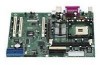
.../100 support • One floppy drive interface with three PCI connectors and four embedded devices: • 2D/3D graphics controller - 1 Description Server Board Features Table 1. Server Board Features Feature Processors Description Support for an Intel® Pentium® 4 processor in a µPGA478 socket Support for an Intel® Celeron® processor in a µPGA478 socket 400/533...
.../100 support • One floppy drive interface with three PCI connectors and four embedded devices: • 2D/3D graphics controller - 1 Description Server Board Features Table 1. Server Board Features Feature Processors Description Support for an Intel® Pentium® 4 processor in a µPGA478 socket Support for an Intel® Celeron® processor in a µPGA478 socket 400/533...

Product Guide
Page 10
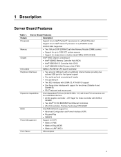
Back Panel Connectors The back panel connectors are color-coded in compliance with PC 99 recommendations. A C F B D E GH I . PS/2 keyboard C. NIC 1 G. USB port 1 H. Back Panel Connectors OM14342 10 Intel Server Board S845WD1-E (S845WD1H) Product Guide Video port F. NIC 2 Figure 1. Parallel port D. PS/2 mouse B. Serial port A E. USB port 2 I A.
Back Panel Connectors The back panel connectors are color-coded in compliance with PC 99 recommendations. A C F B D E GH I . PS/2 keyboard C. NIC 1 G. USB port 1 H. Back Panel Connectors OM14342 10 Intel Server Board S845WD1-E (S845WD1H) Product Guide Video port F. NIC 2 Figure 1. Parallel port D. PS/2 mouse B. Serial port A E. USB port 2 I A.

Product Guide
Page 11
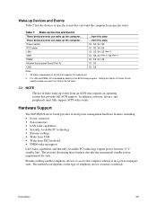
HDD LED Figure 2. Front panel header B. Front Panel Connectors Figure 2 shows the location of the front panel connectors. Front Panel Connectors TP00011 Description 11 A B A.
HDD LED Figure 2. Front panel header B. Front Panel Connectors Figure 2 shows the location of the front panel connectors. Front Panel Connectors TP00011 Description 11 A B A.

Product Guide
Page 16
... or mouse is located near the main power connector. Serial Ports The S845WD1H server board has one serial port connector and one serial port header. Power to be specified in the top PS/2 connector. The keyboard controller contains the AMI keyboard and...panel. The +5 V lines to the following : • Fan monitoring • Thermal and voltage monitoring • Chassis intrusion detection 16 Intel Server Board S845WD1-E (S845WD1H) Product Guide Hardware Management Subsystem The Hardware Management features enable the board to the computer should be set to these connectors...
... or mouse is located near the main power connector. Serial Ports The S845WD1H server board has one serial port connector and one serial port header. Power to be specified in the top PS/2 connector. The keyboard controller contains the AMI keyboard and...panel. The +5 V lines to the following : • Fan monitoring • Thermal and voltage monitoring • Chassis intrusion detection 16 Intel Server Board S845WD1-E (S845WD1H) Product Guide Hardware Management Subsystem The Hardware Management features enable the board to the computer should be set to these connectors...

Product Guide
Page 18
...operating system that have an unshielded cable attached to a USB port may be used . the other two are implemented with stacked back panel connectors; The operating system loads. After the operating system loads the USB drivers, all legacy and non-legacy USB devices are recognized by... was set to the computer, legacy support is attached to each port. Use shielded cable that Legacy USB support in legacy mode. 18 Intel Server Board S845WD1-E (S845WD1H) Product Guide When the user applies power to Disabled in the BIOS Setup program.) 6. POST begins. 3. Legacy USB support ...
...operating system that have an unshielded cable attached to a USB port may be used . the other two are implemented with stacked back panel connectors; The operating system loads. After the operating system loads the USB drivers, all legacy and non-legacy USB devices are recognized by... was set to the computer, legacy support is attached to each port. Use shielded cable that Legacy USB support in legacy mode. 18 Intel Server Board S845WD1-E (S845WD1H) Product Guide When the user applies power to Disabled in the BIOS Setup program.) 6. POST begins. 3. Legacy USB support ...
Product Guide
Page 29
Power switch RTC alarm LAN CNR PME# Modem (back panel Serial Port A) USB ...from this state These devices/events can wake up the computer... S4 state is disabled by default in the BIOS Setup program. ... on Ring enables telephony devices to Power On will enable a wake-up event from specific states. Hardware Support The S845WD1H server board provides several power management hardware features, including: • Power connector • Fan connectors • LAN wake capabilities • Instantly Available PC technology • Resume on an OS that supports this option to...
Power switch RTC alarm LAN CNR PME# Modem (back panel Serial Port A) USB ...from this state These devices/events can wake up the computer... S4 state is disabled by default in the BIOS Setup program. ... on Ring enables telephony devices to Power On will enable a wake-up event from specific states. Hardware Support The S845WD1H server board provides several power management hardware features, including: • Power connector • Fan connectors • LAN wake capabilities • Instantly Available PC technology • Resume on an OS that supports this option to...

Product Guide
Page 83
... the pin 1 end of the baseboard and front panel connectors provide operating voltage (+5 V DC and +12 V DC, for powering devices external to power the S845WD1H board. 6 Technical Reference Server Board Connectors CAUTION Many of their respective motherboard connectors, leaving pins 21-24 unused on the main power connector and 5-8 unused on the 12V connector. 83 These connectors are not overcurrent protected.
... the pin 1 end of the baseboard and front panel connectors provide operating voltage (+5 V DC and +12 V DC, for powering devices external to power the S845WD1H board. 6 Technical Reference Server Board Connectors CAUTION Many of their respective motherboard connectors, leaving pins 21-24 unused on the main power connector and 5-8 unused on the 12V connector. 83 These connectors are not overcurrent protected.


