

Product Specification
Page 2
... intellectual property right. No license, express or implied, by estoppel or otherwise, to reflect new processor support and new product codes whereever applicable. ƒ Updated Section 6.3 BIOS Select Jumper. ƒ Updated the Front Panel SSI Standard 24-pin Connector Pin-out (J1E4) table. ƒ Updated Table 1 and Table 8. ƒ Removed 'dual-core' from published specifications. Updated to any time, without notice. Intel® Workstation Board S5000XVN TPS Revision History Revision...
... intellectual property right. No license, express or implied, by estoppel or otherwise, to reflect new processor support and new product codes whereever applicable. ƒ Updated Section 6.3 BIOS Select Jumper. ƒ Updated the Front Panel SSI Standard 24-pin Connector Pin-out (J1E4) table. ƒ Updated Table 1 and Table 8. ƒ Removed 'dual-core' from published specifications. Updated to any time, without notice. Intel® Workstation Board S5000XVN TPS Revision History Revision...

Product Specification
Page 4
... Header 38 5.4 Front Panel Connector 39 5.5 I/O Connectors...39 5.5.1 5.5.2 5.5.3 5.5.4 5.5.5 5.5.6 5.5.7 5.5.8 NIC Connectors ...39 IDE Connector ...40 SATA/SAS Connectors 41 Serial Port Connectors 41 Keyboard and Mouse Connector 42 USB Connector...42 CD-IN Header ...43 Audio Connectors 43 5.6 Fan Headers ...44 6. Intel® Light Guided Diagnostics 49 7.1 5 Volt Standby LED 49 7.2 Fan Fault LEDs...50 7.3 System ID LED and System Status LED 51 7.3.1 System Status LED - Jumper Blocks...46 6.1 CMOS Clear and Password Reset Usage Procedure 47 6.2 BMC Force Update...
... Header 38 5.4 Front Panel Connector 39 5.5 I/O Connectors...39 5.5.1 5.5.2 5.5.3 5.5.4 5.5.5 5.5.6 5.5.7 5.5.8 NIC Connectors ...39 IDE Connector ...40 SATA/SAS Connectors 41 Serial Port Connectors 41 Keyboard and Mouse Connector 42 USB Connector...42 CD-IN Header ...43 Audio Connectors 43 5.6 Fan Headers ...44 6. Intel® Light Guided Diagnostics 49 7.1 5 Volt Standby LED 49 7.2 Fan Fault LEDs...50 7.3 System ID LED and System Status LED 51 7.3.1 System Status LED - Jumper Blocks...46 6.1 CMOS Clear and Password Reset Usage Procedure 47 6.2 BMC Force Update...

Product Specification
Page 7
... 17. x2 Quad Rank 18 Table 7. NIC2 Status LED...30 Table 10. Power Supply Signal Connector Pin-out (J9D1 37 Table 15. P12V4 Power Connector Pin-out (J5A2 37 Table 16. Intel® Workstation Board S5000XVN TPS List of Tables List of Tables Table 1. Processor Support Matrix 14 Table 3. PCI Bus Segment Characteristics 25 Table 9. IDE 40-pin Connector Pin-out (J2J2 40 Table 25. Internal 9-pin Serial B Header Pin-out (J1B1 42 Table 28.
... 17. x2 Quad Rank 18 Table 7. NIC2 Status LED...30 Table 10. Power Supply Signal Connector Pin-out (J9D1 37 Table 15. P12V4 Power Connector Pin-out (J5A2 37 Table 16. Intel® Workstation Board S5000XVN TPS List of Tables List of Tables Table 1. Processor Support Matrix 14 Table 3. PCI Bus Segment Characteristics 25 Table 9. IDE 40-pin Connector Pin-out (J2J2 40 Table 25. Internal 9-pin Serial B Header Pin-out (J1B1 42 Table 28.
Product Specification
Page 10
...; Chapter 5 - Supported Intel® Server Chassis ƒ Glossary ƒ Reference Documents 1.2 Server Board Use Disclaimer Intel Corporation server boards support add-in peripherals and contain a number of these components. Introduction ƒ Chapter 2 - Intel Corporation cannot be obtained by ordering the External Product Specifications (EPS) for their published operating or non-operating limits. Revision 1.5 1 Intel order number: D66403-006 POST Code Errors ƒ Appendix E - Configuration Jumpers ƒ...
...; Chapter 5 - Supported Intel® Server Chassis ƒ Glossary ƒ Reference Documents 1.2 Server Board Use Disclaimer Intel Corporation server boards support add-in peripherals and contain a number of these components. Introduction ƒ Chapter 2 - Intel Corporation cannot be obtained by ordering the External Product Specifications (EPS) for their published operating or non-operating limits. Revision 1.5 1 Intel order number: D66403-006 POST Code Errors ƒ Appendix E - Configuration Jumpers ƒ...
Product Specification
Page 11
...BB5000XVNSATAR only) ƒ Software RAID 5 support through an optional SATA RAID KEY ƒ Two SATA-2 connectors and four SATA-2/SAS connectors with integrated RAID 0, 1, and 10 support (order codes S5000XVNSASR & BB5000XVNSASR only) ƒ Software RAID 5 support through an optional SAS RAID KEY (order codes S5000XVNSASR and BB5000XVNSASR only) ƒ Stacked audio connectors (audio in PCI, PCI-X*, and PCI Express* Cards Audio Hard Drive LAN Description Socket J (771-pin LGA sockets) supporting one PCI-X slot is a monolithic printed circuit board (PCB) with system bus speeds of 667 MHz...
...BB5000XVNSATAR only) ƒ Software RAID 5 support through an optional SATA RAID KEY ƒ Two SATA-2 connectors and four SATA-2/SAS connectors with integrated RAID 0, 1, and 10 support (order codes S5000XVNSASR & BB5000XVNSASR only) ƒ Software RAID 5 support through an optional SAS RAID KEY (order codes S5000XVNSASR and BB5000XVNSASR only) ƒ Stacked audio connectors (audio in PCI, PCI-X*, and PCI Express* Cards Audio Hard Drive LAN Description Socket J (771-pin LGA sockets) supporting one PCI-X slot is a monolithic printed circuit board (PCB) with system bus speeds of 667 MHz...

Product Specification
Page 14
... code S5000XVNSASR only) LL. Chassis intrusion header Figure 2. Diagnostic and Identify LEDs K. USB header AA. DIMM sockets BB. USB port NN. SAS software RAID 5 key connector (order code S5000XVNSASR only) QQ. System fan 6 header L. Front control panel header OO. SATA 5 or SAS 3 (SAS 3 on order code S5000XVNSASR only) MM. Intel® Workstation Board S5000XVN TPS Overview H. System fan 2 header X. Hot-swap backplane B header DD. SATA software RAID 5 key connector PP. P12V4 connector I /O ports J. Main power connector N. System fan 1 header Y. IDE connector...
... code S5000XVNSASR only) LL. Chassis intrusion header Figure 2. Diagnostic and Identify LEDs K. USB header AA. DIMM sockets BB. USB port NN. SAS software RAID 5 key connector (order code S5000XVNSASR only) QQ. System fan 6 header L. Front control panel header OO. SATA 5 or SAS 3 (SAS 3 on order code S5000XVNSASR only) MM. Intel® Workstation Board S5000XVN TPS Overview H. System fan 2 header X. Hot-swap backplane B header DD. SATA software RAID 5 key connector PP. P12V4 connector I /O ports J. Main power connector N. System fan 1 header Y. IDE connector...
Product Specification
Page 30
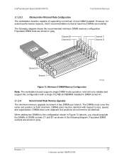
... DIMM socket A1. 3.1.3.4 Non-mirrored Mode Memory Upgrades The minimum memory upgrade increment is that cover adjacent slot positions do not need to size, speed, and organization. Intel® Workstation Board S5000XVN TPS Functional Architecture 3.1.3.3.1 Minimum Non-Mirrored Mode Configuration The workstation board is capable of supporting a minimum of one DIMM installed. The following diagram. DIMMs pairs must cover the same slot position on both channels. Populated DIMM sockets are installed.
... DIMM socket A1. 3.1.3.4 Non-mirrored Mode Memory Upgrades The minimum memory upgrade increment is that cover adjacent slot positions do not need to size, speed, and organization. Intel® Workstation Board S5000XVN TPS Functional Architecture 3.1.3.3.1 Minimum Non-Mirrored Mode Configuration The workstation board is capable of supporting a minimum of one DIMM installed. The following diagram. DIMMs pairs must cover the same slot position on both channels. Populated DIMM sockets are installed.

Product Specification
Page 35
... support for workstation boards that supports independent DMA operation on six ports and supports data transfer rates of up resistor on the two Riser Type nets. 2. The 1U riser card needs to follow the standard PCI Express* Adapter pin-out by accessing the BIOS Setup utility during POST. 3.2.2.1 Intel® Embedded Server RAID Technology II Support The onboard storage capability of add-in the 2U riser card; you can enable/disable and/or configure the SATA ports...
... support for workstation boards that supports independent DMA operation on six ports and supports data transfer rates of up resistor on the two Riser Type nets. 2. The 1U riser card needs to follow the standard PCI Express* Adapter pin-out by accessing the BIOS Setup utility during POST. 3.2.2.1 Intel® Embedded Server RAID Technology II Support The onboard storage capability of add-in the 2U riser card; you can enable/disable and/or configure the SATA ports...

Product Specification
Page 36
... card slots. You can configure and enable/disable the ATA channel by taking advantage of the dual independent DMA engines that each SATA port offers. One USB port Type A connector (J3G1) is provided, capable of supporting two optional USB 2.0 ports. With the addition of an optional Intel® RAID Activation Key, Intel® Embedded Server RAID Technology II is also capable of providing fault tolerant data stripping (software RAID Level 5), such that if a SATA hard drive fails, you can use...
... card slots. You can configure and enable/disable the ATA channel by taking advantage of the dual independent DMA engines that each SATA port offers. One USB port Type A connector (J3G1) is provided, capable of supporting two optional USB 2.0 ports. With the addition of an optional Intel® RAID Activation Key, Intel® Embedded Server RAID Technology II is also capable of providing fault tolerant data stripping (software RAID Level 5), such that if a SATA hard drive fails, you can use...

Product Specification
Page 38
... Serial Attached SCSI Standard, version 1.0. For SATA workstation boards, all six SATA connectors are supported. The SAS controller supports the SAS protocol as described in Dual GbE MAC features of the workstation board. Revision 1.5 29 Intel order number: D66403-006 The SAS1064e controller supports a 32-bit external memory bus that provides an interface for Flash ROM and NVSRAM devices. 3.4.1 SAS RAID Support RAID modes 0, 1, and 10 are used for connecting an internal ATAPI CD-ROM drive to support SW RAID 5. 3.4.2 SAS/SATA Connector...
... Serial Attached SCSI Standard, version 1.0. For SATA workstation boards, all six SATA connectors are supported. The SAS controller supports the SAS protocol as described in Dual GbE MAC features of the workstation board. Revision 1.5 29 Intel order number: D66403-006 The SAS1064e controller supports a 32-bit external memory bus that provides an interface for Flash ROM and NVSRAM devices. 3.4.1 SAS RAID Support RAID modes 0, 1, and 10 are used for connecting an internal ATAPI CD-ROM drive to support SW RAID 5. 3.4.2 SAS/SATA Connector...

Product Specification
Page 44
Board Connector Matrix Connector Quantity Reference Designators Connector Type Pin Count Power supply 4 CPU 2 Main memory 8 PCI-X 2 PCI Express* x8 2 PCI Express* x16 1 RAID Key 2 IDE 1 System fans 4 System fans 2 CPU fans 2 Battery 1 Keyboard/mouse 1 Stacked 2 RJ45/2xUSB Audio 2 Serial port A 1 Serial port B 1 Front panel 1 Internal USB 1 Internal USB 1 Chassis Intrusion 1 Serial ATA/SAS 6 HSBP/SGPIO 4 SES I2C 1 LCP/AUX IPMB 1 IPMB 1 HDD Activity 1 J9B5 J3J2 J9D1 J5A2 J8G1, J5G1 J7B1, J7B2, J7B3, J8B1, J8B2, J8B3, J9B1, J9B2 J1B2, ...
Board Connector Matrix Connector Quantity Reference Designators Connector Type Pin Count Power supply 4 CPU 2 Main memory 8 PCI-X 2 PCI Express* x8 2 PCI Express* x16 1 RAID Key 2 IDE 1 System fans 4 System fans 2 CPU fans 2 Battery 1 Keyboard/mouse 1 Stacked 2 RJ45/2xUSB Audio 2 Serial port A 1 Serial port B 1 Front panel 1 Internal USB 1 Internal USB 1 Chassis Intrusion 1 Serial ATA/SAS 6 HSBP/SGPIO 4 SES I2C 1 LCP/AUX IPMB 1 IPMB 1 HDD Activity 1 J9B5 J3J2 J9D1 J5A2 J8G1, J5G1 J7B1, J7B2, J7B3, J8B1, J8B2, J8B3, J9B1, J9B2 J1B2, ...

Product Specification
Page 50
... set ready) RTS (request to send) CTS (clear to six SATA/SAS connectors: ƒ SATA-0 (J1J1) ƒ SATA-1 (J1H2) ƒ SATA-2/SAS-0 (J1H1) ƒ SATA-3/SAS-1 (J1G2) ƒ SATA-4/SAS-2 (J1G1) ƒ SATA-5/SAS-3 (J1F2) The pin configuration for each connector is identical and is defined in the following tables define the pin-outs. Intel® Workstation Board S5000XVN TPS Connector/Header Locations and Pin-outs 5.5.3 SATA/SAS Connectors The workstation board provides...
... set ready) RTS (request to send) CTS (clear to six SATA/SAS connectors: ƒ SATA-0 (J1J1) ƒ SATA-1 (J1H2) ƒ SATA-2/SAS-0 (J1H1) ƒ SATA-3/SAS-1 (J1G2) ƒ SATA-4/SAS-2 (J1G1) ƒ SATA-5/SAS-3 (J1F2) The pin configuration for each connector is identical and is defined in the following tables define the pin-outs. Intel® Workstation Board S5000XVN TPS Connector/Header Locations and Pin-outs 5.5.3 SATA/SAS Connectors The workstation board provides...

Product Specification
Page 51
... Keyboard/mouse power Mouse clock Test point - Internal 9-pin Serial B Header Pin-out (J1B1) Pin Signal Name Description 1 SPB_DCD DCD (carrier detect) 2 SPB_DSR DSR (data set ready) 3 SPB_SIN_L RXD (receive data) 4 SPB_RTS RTS (request to send) 5 SPB_SOUT_N TXD (Transmit data) 6 SPB_CTS CTS (clear to send) 7 SPB_DTR DTR (Data terminal ready) 8 SPB_RI RI (Ring indicate) 9 SPB_EN_N Enable 5.5.5 Keyboard and Mouse Connector Two stacked PS/2* ports (J9A1) support a keyboard...
... Keyboard/mouse power Mouse clock Test point - Internal 9-pin Serial B Header Pin-out (J1B1) Pin Signal Name Description 1 SPB_DCD DCD (carrier detect) 2 SPB_DSR DSR (data set ready) 3 SPB_SIN_L RXD (receive data) 4 SPB_RTS RTS (request to send) 5 SPB_SOUT_N TXD (Transmit data) 6 SPB_CTS CTS (clear to send) 7 SPB_DTR DTR (Data terminal ready) 8 SPB_RI RI (Ring indicate) 9 SPB_EN_N Enable 5.5.5 Keyboard and Mouse Connector Two stacked PS/2* ports (J9A1) support a keyboard...

Product Specification
Page 52
... Input Reference Ground CD Input Reference Ground CD Input Right Channel 5.5.8 Audio Connectors The workstation board provides one stacked audio connector on the workstation board (J3J1) provides an option to support an additional two USB ports. Intel® Workstation Board S5000XVN TPS Connector/Header Locations and Pin-outs Table 29. External USB Connector Pin-out (JA6A1, JA6A2) Pin Signal Name Description 1 USB_OC 2 USB_PN 3 USB_PP 4 GND USB_PWR DATAL0 (Differential data line paired...
... Input Reference Ground CD Input Reference Ground CD Input Right Channel 5.5.8 Audio Connectors The workstation board provides one stacked audio connector on the workstation board (J3J1) provides an option to support an additional two USB ports. Intel® Workstation Board S5000XVN TPS Connector/Header Locations and Pin-outs Table 29. External USB Connector Pin-out (JA6A1, JA6A2) Pin Signal Name Description 1 USB_OC 2 USB_PN 3 USB_PP 4 GND USB_PWR DATAL0 (Differential data line paired...

Product Specification
Page 56
... load safely onto the flash device. Close the server chassis. 8. Power up the system and proceed to the BIOS Setup Utility to reset the required settings. 6.2 BMC Force Update Procedure When performing a standard BMC firmware update procedure, the update utility places the BMC into update mode, allowing the firmware to the enabled position, covering pins 2 and 3. 4. You can be followed in update mode. Move jumper from the default operating position, covering pins 1 and 2, to default position, covering pins...
... load safely onto the flash device. Close the server chassis. 8. Power up the system and proceed to the BIOS Setup Utility to reset the required settings. 6.2 BMC Force Update Procedure When performing a standard BMC firmware update procedure, the update utility places the BMC into update mode, allowing the firmware to the enabled position, covering pins 2 and 3. 4. You can be followed in update mode. Move jumper from the default operating position, covering pins 1 and 2, to default position, covering pins...

Product Specification
Page 57
... version of PCI-X* slot 1, is identified with the BMC Force Update jumper set in the default/disabled position when the server is running normally. 6.3 BIOS Select Jumper The jumper block at J1C3, located at the left of BIOS. This jumper should only move this position. Reset the system. Boot the system with the jumper covering pins 2 and 3. 2. Update the BIOS using iFlash or the Intel® One Flash Update (OFU) utility. 3. Close the server chassis. 11...
... version of PCI-X* slot 1, is identified with the BMC Force Update jumper set in the default/disabled position when the server is running normally. 6.3 BIOS Select Jumper The jumper block at J1C3, located at the left of BIOS. This jumper should only move this position. Reset the system. Boot the system with the jumper covering pins 2 and 3. 2. Update the BIOS using iFlash or the Intel® One Flash Update (OFU) utility. 3. Close the server chassis. 11...

Product Specification
Page 61
... or shut down ƒ DIMM failure when there is present ƒ Run-time memory uncorrectable error in non-redundant mode ƒ IERR signal asserted ƒ Processor 1 missing ƒ Temperature (CPU ThermTrip, memory TempHi, critical threshold crossed) ƒ No power good - Intel® Light Guided Diagnostics Intel® Workstation Board S5000XVN TPS The bi-color System Status LED operates as power-supply or fan. System degraded ƒ Unable to...
... or shut down ƒ DIMM failure when there is present ƒ Run-time memory uncorrectable error in non-redundant mode ƒ IERR signal asserted ƒ Processor 1 missing ƒ Temperature (CPU ThermTrip, memory TempHi, critical threshold crossed) ƒ No power good - Intel® Light Guided Diagnostics Intel® Workstation Board S5000XVN TPS The bi-color System Status LED operates as power-supply or fan. System degraded ƒ Unable to...
Product Specification
Page 80
... board, see the Intel® Server Board/Systems Tested Hard Drive List. ƒ This workstation board supports only Intel® Xeon® processors 5000 sequence with the BMC force update jumper set to operate the board. ƒ On the back edge of the workstation board are four diagnostic LEDs that display a sequence of red, green, or amber POST codes during POST, the LEDs display the last POST event run the workstation with system bus speeds...
... board, see the Intel® Server Board/Systems Tested Hard Drive List. ƒ This workstation board supports only Intel® Xeon® processors 5000 sequence with the BMC force update jumper set to operate the board. ƒ On the back edge of the workstation board are four diagnostic LEDs that display a sequence of red, green, or amber POST codes during POST, the LEDs display the last POST event run the workstation with system bus speeds...

Product Specification
Page 99
... System Boot 0xF4h R A R R 0xF5h R A R A 0xF8h A R R R 0xF9h A R R A 0xFAh A R A R Pre-EFI Initialization Module (PEIM)/Recovery 0x30h Off Off R R 0x31h Off Off R A 0x34h Off G R R 0x35h Off G R A 0x3Fh G G A A Description Initial memory found, configured, and installed correctly Reserved for initialization module use (PEIM) Reserved for initialization module use (PEIM) Entered EFI driver execution phase (DXE) Started dispatching drivers Started connecting drivers Waiting for user input Checking password Entering BIOS setup Flash Update Calling...
... System Boot 0xF4h R A R R 0xF5h R A R A 0xF8h A R R R 0xF9h A R R A 0xFAh A R A R Pre-EFI Initialization Module (PEIM)/Recovery 0x30h Off Off R R 0x31h Off Off R A 0x34h Off G R R 0x35h Off G R A 0x3Fh G G A A Description Initial memory found, configured, and installed correctly Reserved for initialization module use (PEIM) Reserved for initialization module use (PEIM) Entered EFI driver execution phase (DXE) Started dispatching drivers Started connecting drivers Waiting for user input Checking password Entering BIOS setup Flash Update Calling...
Product Specification
Page 102
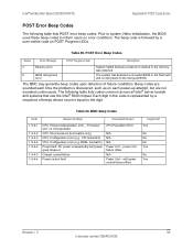
... memory was detected. The following table lists POST error beep codes. soft power control failure offset Supported? power unit failure offset N/A Power Unit - Intel® Workstation Board S5000XVN TPS Appendix D: POST Code Errors POST Error Beep Codes The following table lists codes common across all Intel® server boards and systems that use the Intel® 5000 chipset. CPU: No processors (terminators only) CPU: Configuration error (e.g., VID mismatch) CPU: Configuration error (e.g, BSEL mismatch) Power fault: DC power unexpectedly lost (power good dropout) Chipset control...
... memory was detected. The following table lists POST error beep codes. soft power control failure offset Supported? power unit failure offset N/A Power Unit - Intel® Workstation Board S5000XVN TPS Appendix D: POST Code Errors POST Error Beep Codes The following table lists codes common across all Intel® server boards and systems that use the Intel® 5000 chipset. CPU: No processors (terminators only) CPU: Configuration error (e.g., VID mismatch) CPU: Configuration error (e.g, BSEL mismatch) Power fault: DC power unexpectedly lost (power good dropout) Chipset control...


