Product Specification
Page 4
... Intel® Server Boards S3200SH/S3210SH TPS 4.3 BIOS Setup Utility 44 4.3.1 Operation ...44 4.3.2 Server Platform Setup Screens 47 4.4 Loading BIOS Defaults 75 4.5 Multiple Boot Blocks 75 4.6 Recovery Mode...75 4.7 Intel® Matrix Storage Manager 76 4.8 Intel® Embedded Server RAID...6. Connectors and Jumper Blocks 86 6.1 Power Connectors 86 6.1.1 6.2 Main Power Connector 86 Intel® Riser Card for L SKU 87 6.3 SMBus Connector 87 6.4 Front Panel Connector 87 6.5 I/O Connectors...88 6.5.1 VGA Connector...88 6.5.2 NIC Connectors ...88 6.5.3 ...
... Intel® Server Boards S3200SH/S3210SH TPS 4.3 BIOS Setup Utility 44 4.3.1 Operation ...44 4.3.2 Server Platform Setup Screens 47 4.4 Loading BIOS Defaults 75 4.5 Multiple Boot Blocks 75 4.6 Recovery Mode...75 4.7 Intel® Matrix Storage Manager 76 4.8 Intel® Embedded Server RAID...6. Connectors and Jumper Blocks 86 6.1 Power Connectors 86 6.1.1 6.2 Main Power Connector 86 Intel® Riser Card for L SKU 87 6.3 SMBus Connector 87 6.4 Front Panel Connector 87 6.5 I/O Connectors...88 6.5.1 VGA Connector...88 6.5.2 NIC Connectors ...88 6.5.3 ...
Product Specification
Page 5
... Contents 6.7 Miscellaneous Headers and Connectors 92 6.7.1 Back Panel I/O Connectors 92 6.7.2 Chassis Intrusion Header 93 6.7.3 HDD Active LED Header 93 6.7.4 IPMB ...93 6.7.5 HSBP ...93 6.7.6 SATA SGPIO ...94 6.8 Jumper Blocks ...94 6.8.1 CMOS Clear and Password Reset Usage Procedure 94 6.8.2 BMC Force Update Procedure 95 7. Intel® Server Boards S3200SH/S3210SH TPS Table of Conformity (BSMI 107...
... Contents 6.7 Miscellaneous Headers and Connectors 92 6.7.1 Back Panel I/O Connectors 92 6.7.2 Chassis Intrusion Header 93 6.7.3 HDD Active LED Header 93 6.7.4 IPMB ...93 6.7.5 HSBP ...93 6.7.6 SATA SGPIO ...94 6.8 Jumper Blocks ...94 6.8.1 CMOS Clear and Password Reset Usage Procedure 94 6.8.2 BMC Force Update Procedure 95 7. Intel® Server Boards S3200SH/S3210SH TPS Table of Conformity (BSMI 107...
Product Specification
Page 8
Intel® Server Board S3200SHV Back Panel I /O Connectors ...92 Figure 36. List of Diagnostic LEDs on Server Board 81 Figure 35. Intel® Server Board S3200SH Mechanical Drawing 109 Figure 40. Pedestal Mount I /O Shield Mechanical Drawing for Intel® Server Boards S3200SH- Intel® Server Board S3210SHLX / S3210SHLC / S3200SHL Back Panel I /O Connectors 93 Figure 37. Turn On/Off Timing (Power Supply Signals 100 Figure 39. Pedestal Mount I /O Shield...
Intel® Server Board S3200SHV Back Panel I /O Connectors ...92 Figure 36. List of Diagnostic LEDs on Server Board 81 Figure 35. Intel® Server Board S3200SH Mechanical Drawing 109 Figure 40. Pedestal Mount I /O Shield Mechanical Drawing for Intel® Server Boards S3200SH- Intel® Server Board S3210SHLX / S3210SHLC / S3200SHL Back Panel I /O Connectors 93 Figure 37. Turn On/Off Timing (Power Supply Signals 100 Figure 39. Pedestal Mount I /O Shield...
Product Specification
Page 10
...USB Connectors Pin-out (J5B1 91 Table 60. Absolute Maximum Ratings 96 Table 65. Output Voltage Timing 98 x Revision 1.8 Intel Order Number: E14960-009 List of Tables Intel® Server Boards S3200SH/S3210SH TPS Table 34. Setup Utility - Error Manager Screen Fields 73 Table 40. Setup Utility - POST Error Messages... 89 Table 56. Chassis Intrusion Header (J1B2) Pin-out 93 Table 63. MTBF Data...96 Table 66. Event List ...77 Table 42. Front Panel 24-Pin Header Pin-out (J1K2 87 Table 52. Four-pin Fan Headers Pin-out (J4D1, J1K2, J7K1, and J4K1J6B2 92 Table 62....
...USB Connectors Pin-out (J5B1 91 Table 60. Absolute Maximum Ratings 96 Table 65. Output Voltage Timing 98 x Revision 1.8 Intel Order Number: E14960-009 List of Tables Intel® Server Boards S3200SH/S3210SH TPS Table 34. Setup Utility - Error Manager Screen Fields 73 Table 40. Setup Utility - POST Error Messages... 89 Table 56. Chassis Intrusion Header (J1B2) Pin-out 93 Table 63. MTBF Data...96 Table 66. Event List ...77 Table 42. Front Panel 24-Pin Header Pin-out (J1K2 87 Table 52. Four-pin Fan Headers Pin-out (J4D1, J1K2, J7K1, and J4K1J6B2 92 Table 62....
Product Specification
Page 15
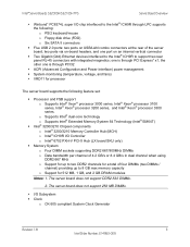
...GB DRAM modules Notes: 1. The server board does not support DDR2-533 DIMMs. 2. o Supports Intel® dual-core technology o Supports Intel® Extended Memory System 64 Technology (Intel® EM64T) ƒ Intel® 3200/3210 Chipset components o Intel® 3200/3210 Memory Controller Hub (MCH) o Intel® ICH9R I /O Subsystem ... Generator Revision 1.8 3 Intel Order Number: E14960-009 one is through PCI Express* x1, the other one port on USB/LAN combo connectors at the rear of four DIMMs (two DIMMs / channel) providing up to support two rear panel RJ-45 connectors with ...
...GB DRAM modules Notes: 1. The server board does not support DDR2-533 DIMMs. 2. o Supports Intel® dual-core technology o Supports Intel® Extended Memory System 64 Technology (Intel® EM64T) ƒ Intel® 3200/3210 Chipset components o Intel® 3200/3210 Memory Controller Hub (MCH) o Intel® ICH9R I /O Subsystem ... Generator Revision 1.8 3 Intel Order Number: E14960-009 one is through PCI Express* x1, the other one port on USB/LAN combo connectors at the rear of four DIMMs (two DIMMs / channel) providing up to support two rear panel RJ-45 connectors with ...
Product Specification
Page 16
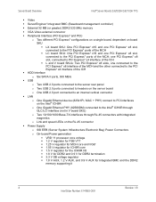
... speed LEDs on the Intel® ICH9R o One Gigabit Ethernet PHY (82566DM) connected to the PCI Express* ports of the ICH ƒ HDD Interface o Six SATA II ports, 300 MB/s ƒ USB o Two USB 2.0 ports connected to the server rear panel o Two USB 2.0 ports connected to headers on the server board o One USB 2.0 port connected...
... speed LEDs on the Intel® ICH9R o One Gigabit Ethernet PHY (82566DM) connected to the PCI Express* ports of the ICH ƒ HDD Interface o Six SATA II ports, 300 MB/s ƒ USB o Two USB 2.0 ports connected to the server rear panel o Two USB 2.0 ports connected to headers on the server board o One USB 2.0 port connected...

Product Specification
Page 17
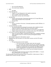
... server board headers) o SSI-EEB ATX power connectors o One 4-pin auxiliary power connector o One stacked DB-15 VGA/DB-9 serial port connector o Six 7-pin SATA II connectors o 60-pin XDP connector o Four 4-pin, 0.10-inch pitch fan headers o 24-Pin, SSI-EEB, front panel connector Revision 1.8 5 Intel Order...o Serial o Floppy o PS/2 keyboard o PS/2 mouse ƒ Power Management Modes Supported (ACPI [Advanced Configuration and Power Interface] Sleep states) o S0 - Intel® Server Boards S3200SH/S3210SH TPS Server Board Overview ƒ System Management o Processor on -suspend o S4 -
... server board headers) o SSI-EEB ATX power connectors o One 4-pin auxiliary power connector o One stacked DB-15 VGA/DB-9 serial port connector o Six 7-pin SATA II connectors o 60-pin XDP connector o Four 4-pin, 0.10-inch pitch fan headers o 24-Pin, SSI-EEB, front panel connector Revision 1.8 5 Intel Order...o Serial o Floppy o PS/2 keyboard o PS/2 mouse ƒ Power Management Modes Supported (ACPI [Advanced Configuration and Power Interface] Sleep states) o S0 - Intel® Server Boards S3200SH/S3210SH TPS Server Board Overview ƒ System Management o Processor on -suspend o S4 -
Product Specification
Page 18
...monitoring. ƒ SSI-compliant connectors for SSI interface support ƒ Standard 24-pin SSI front panel, 2x12 main power connector, and 2x4 CPU power connector ƒ Fan Support o Five general purpose...Server Board Overview Intel® Server Boards S3200SH/S3210SH TPS o One 4-pin SATA RAID Key o One 2-pin intrusion detection ƒ BIOS o EFI BIOS ƒ Power Management o Support for Power Management of the LX board SKU. The following figure shows the board layout of all PC-compatible I /O controller (SMSC* SCH5027D) providing all capable components o ACPI-compliant motherboard...
...monitoring. ƒ SSI-compliant connectors for SSI interface support ƒ Standard 24-pin SSI front panel, 2x12 main power connector, and 2x4 CPU power connector ƒ Fan Support o Five general purpose...Server Board Overview Intel® Server Boards S3200SH/S3210SH TPS o One 4-pin SATA RAID Key o One 2-pin intrusion detection ƒ BIOS o EFI BIOS ƒ Power Management o Support for Power Management of the LX board SKU. The following figure shows the board layout of all PC-compatible I /O controller (SMSC* SCH5027D) providing all capable components o ACPI-compliant motherboard...

Product Specification
Page 19
... Front Panel Connector CC Chassis Intrusion Jumper DD Floppy Connector EE Internal USB FF External USB GG CMOS Clear Jumper HH BMC Force Update Jumper II BIOS Recovery Jumper JJ BMC Boot Block WP Jumper KK Serial Port Connector Revision 1.8 7 Intel Order Number: E14960-009 Intel® Server Boards S3200SH/S3210SH TPS A B C D EF GH IJ Server Board...
... Front Panel Connector CC Chassis Intrusion Jumper DD Floppy Connector EE Internal USB FF External USB GG CMOS Clear Jumper HH BMC Force Update Jumper II BIOS Recovery Jumper JJ BMC Boot Block WP Jumper KK Serial Port Connector Revision 1.8 7 Intel Order Number: E14960-009 Intel® Server Boards S3200SH/S3210SH TPS A B C D EF GH IJ Server Board...
Product Specification
Page 20
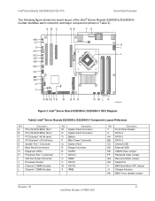
... 2. Server Board Overview Intel® Server Boards S3200SH/S3210SH TPS The following figure shows the board layout of the LC board SKU. Intel® Server Board S3210SHLC Layout Reference Ref Description A PCI (32-bit/33 MHz) Slot 1 B PCI (32-bit/33 MHz) Slot 2 C PCI Express* x8 (x8 lane) D PCI Express* x8 (x4 lane) E PCI Express* x16 F System Fan 1 Connector G Back Panel...
... 2. Server Board Overview Intel® Server Boards S3200SH/S3210SH TPS The following figure shows the board layout of the LC board SKU. Intel® Server Board S3210SHLC Layout Reference Ref Description A PCI (32-bit/33 MHz) Slot 1 B PCI (32-bit/33 MHz) Slot 2 C PCI Express* x8 (x8 lane) D PCI Express* x8 (x4 lane) E PCI Express* x16 F System Fan 1 Connector G Back Panel...
Product Specification
Page 21
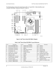
... Panel Connectors G Diagnostic LEDs H Processor Fan 1 Connector I HH GG J FF EE DD CC BB AA Z Y X WVU T S R Q P O NML K AF002310 Figure 3. A letter identifies each connector and major component (shown in Table 3). Intel® Server Board S3200SH-L/S3200SH-V SKU Diagram Table3. Intel® Server Boards S3200SH/S3210SH TPS Server Board Overview The following figure shows the board layout of the Intel® Server Boards S3200SHL/S3200SHV. AB...
... Panel Connectors G Diagnostic LEDs H Processor Fan 1 Connector I HH GG J FF EE DD CC BB AA Z Y X WVU T S R Q P O NML K AF002310 Figure 3. A letter identifies each connector and major component (shown in Table 3). Intel® Server Board S3200SH-L/S3200SH-V SKU Diagram Table3. Intel® Server Boards S3200SH/S3210SH TPS Server Board Overview The following figure shows the board layout of the Intel® Server Boards S3200SHL/S3200SHV. AB...

Product Specification
Page 37
... Enhanced Power Management One of the embedded features of the Intel® ICH9R is a power management controller. The server board provides two external USB ports on the rear panel of the server board. The third/fourth USB port is optional and can support four USB ports. Intel® Server Boards S3200SH/S3210SH TPS Functional Architecture 3.2.3.17 PCI Express* x4...
... Enhanced Power Management One of the embedded features of the Intel® ICH9R is a power management controller. The server board provides two external USB ports on the rear panel of the server board. The third/fourth USB port is optional and can support four USB ports. Intel® Server Boards S3200SH/S3210SH TPS Functional Architecture 3.2.3.17 PCI Express* x4...

Product Specification
Page 72
Setup Utility - Comments No entry allowed No entry allowed Warning: If [Disabled] is selected, NIC1 and NIC2 cannot be...the onboard video controller and an add-in video adapter will be used to lock out the front panel buttons so they cannot be the primary video device. The onboard video controller will be used . PCI... from the Main screen, select the Security option. 60 Revision 1.8 Intel Order Number: E14960-009 Information only. 12 hex digits of the MAC address. Intel® Server Boards S3200SH/S3210SH TPS Advanced PCI Configuration Dual Monitor Video Onboard NIC ROM NIC...
Setup Utility - Comments No entry allowed No entry allowed Warning: If [Disabled] is selected, NIC1 and NIC2 cannot be...the onboard video controller and an add-in video adapter will be used to lock out the front panel buttons so they cannot be the primary video device. The onboard video controller will be used . PCI... from the Main screen, select the Security option. 60 Revision 1.8 Intel Order Number: E14960-009 Information only. 12 hex digits of the MAC address. Intel® Server Boards S3200SH/S3210SH TPS Advanced PCI Configuration Dual Monitor Video Onboard NIC ROM NIC...
Product Specification
Page 73
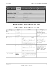
... setup items. Clearing the Admin password also clears the user password. System BIOS Intel® Server Boards S3200SH/S3210SH TPS Main Advanced Security Server Management Boot Options Boot Manager Administrator Password Status User Password Status Set Administrator Password Set User Password Front Panel Lockout [1234abcd] [1234abcd] Enabled/Disabled Figure 21. It is not case sensitive...
... setup items. Clearing the Admin password also clears the user password. System BIOS Intel® Server Boards S3200SH/S3210SH TPS Main Advanced Security Server Management Boot Options Boot Manager Administrator Password Status User Password Status Set Administrator Password Set User Password Front Panel Lockout [1234abcd] [1234abcd] Enabled/Disabled Figure 21. It is not case sensitive...

Product Specification
Page 99
... 4 TP_BP_I2C_HRD_4 Description Data Line GROUND Clock Line Test Point 6.4 Front Panel Connector A standard SSI 24-pin header is provided to the PCI Express* x16 slot on the riser card is designed for L SKU The Intel® Server Board S3200SH-L has a PCI Express* x16 to be populated with PCI ...Express* x16 slot on the Intel® Server Board S3200SH-L. The physical layout to support a system front panel. This riser card is PCI Express* x8.
... 4 TP_BP_I2C_HRD_4 Description Data Line GROUND Clock Line Test Point 6.4 Front Panel Connector A standard SSI 24-pin header is provided to the PCI Express* x16 slot on the riser card is designed for L SKU The Intel® Server Board S3200SH-L has a PCI Express* x16 to be populated with PCI ...Express* x16 slot on the Intel® Server Board S3200SH-L. The physical layout to support a system front panel. This riser card is PCI Express* x8.

Product Specification
Page 104
... Name NC GND USB_FRONT1_INDUCTOR_DP USB_FRONT1_INDUCTOR_DN USB_FNT_PWR Pin 1 3 5 7 9 Signal Name Key GND USB_FRONT2_INDUCTOR_DP USB_FRONT2_INDUCTOR_DN USB_FNT_PWR Pin 2 4 6 8 10 6.6 Fan Headers The server board supports five general-purpose fan headers. Intel® Server Board S3210SHLX / S3210SHLC / S3200SHL Back Panel I /O Connectors Figure 35. Four-pin Fan Headers Pin-out (J4D1, J1K2, J7K1, and J4K1J6B2) Pin Signal Name 1 Ground 2 Fan Power...
... Name NC GND USB_FRONT1_INDUCTOR_DP USB_FRONT1_INDUCTOR_DN USB_FNT_PWR Pin 1 3 5 7 9 Signal Name Key GND USB_FRONT2_INDUCTOR_DP USB_FRONT2_INDUCTOR_DN USB_FNT_PWR Pin 2 4 6 8 10 6.6 Fan Headers The server board supports five general-purpose fan headers. Intel® Server Board S3210SHLX / S3210SHLC / S3200SHL Back Panel I /O Connectors Figure 35. Four-pin Fan Headers Pin-out (J4D1, J1K2, J7K1, and J4K1J6B2) Pin Signal Name 1 Ground 2 Fan Power...

Product Specification
Page 105
...Pin-out Pin 1 2 Signal Name FM_SIO_SCSI_ACT_N TP_SCSI_ACT_PIN2 6.7.4 IPMB There is a 1x2 pin header for connecting to the Intel® Entry Server Chassis SC5299-E hot-swap backplane. Table 63. This jumper is used in chassis that support the SCSI or SATA ...is a 4-pin HSBP connector jumper. The Intel® ICH9R monitors this header. Connectors and Jumper Blocks Keyboard Intel® Server Boards S3200SH/S3210SH TPS Serial A LAN Mouse VGA POST Code LED USB Figure 36. Intel® Server Board S3200SHV Back Panel I/O Connectors 6.7.2 Chassis Intrusion Header A 1x2...
...Pin-out Pin 1 2 Signal Name FM_SIO_SCSI_ACT_N TP_SCSI_ACT_PIN2 6.7.4 IPMB There is a 1x2 pin header for connecting to the Intel® Entry Server Chassis SC5299-E hot-swap backplane. Table 63. This jumper is used in chassis that support the SCSI or SATA ...is a 4-pin HSBP connector jumper. The Intel® ICH9R monitors this header. Connectors and Jumper Blocks Keyboard Intel® Server Boards S3200SH/S3210SH TPS Serial A LAN Mouse VGA POST Code LED USB Figure 36. Intel® Server Board S3200SHV Back Panel I/O Connectors 6.7.2 Chassis Intrusion Header A 1x2...


