
Mechanical Design Guidelines
Page 3
...Guidelines 15 2.1.2.2 Heatsink Clip Load Requirement 15 2.1.2.3 Additional Guidelines 16 2.2 Thermal Requirements 16 2.2.1 Processor Case Temperature 16 2.2.2 Thermal Profile 17 2.2.3 Thermal Solution Design Requirements 17 2.2.4 TCONTROL 18 2.3 Heatsink Design... Requirements 25 3.1.1 Example 26 3.2 Processor Thermal Solution Performance Assessment 27 3.3 Local Ambient Temperature Measurement Guidelines 27 3.4 Processor Case Temperature Measurement Guidelines 30 4 Thermal Management Logic and Thermal Monitor Feature 31 4.1 Processor Power Dissipation 31 4.2 Thermal Monitor ...
...Guidelines 15 2.1.2.2 Heatsink Clip Load Requirement 15 2.1.2.3 Additional Guidelines 16 2.2 Thermal Requirements 16 2.2.1 Processor Case Temperature 16 2.2.2 Thermal Profile 17 2.2.3 Thermal Solution Design Requirements 17 2.2.4 TCONTROL 18 2.3 Heatsink Design... Requirements 25 3.1.1 Example 26 3.2 Processor Thermal Solution Performance Assessment 27 3.3 Local Ambient Temperature Measurement Guidelines 27 3.4 Processor Case Temperature Measurement Guidelines 30 4 Thermal Management Logic and Thermal Monitor Feature 31 4.1 Processor Power Dissipation 31 4.2 Thermal Monitor ...
Mechanical Design Guidelines
Page 5
... Loading 69 A.1 LGA775 Socket Heatsink Considerations 69 A.2 Metric for Heatsink Preload for ATX/uATX Designs Non-Compliant with Intel® Reference Design 69 A.3 Heatsink Preload Requirement Limitations 69 A.3.1 Motherboard Deflection Metric Definition 70 A.3.2 Board Deflection Limits... Conditions 79 Thermal Interface Management 81 C.1 Bond Line Management 81 C.2 Interface Material Area 81 C.3 Interface Material Performance 81 Case Temperature Reference Metrology 83 D.1 Objective and Scope 83 D.2 Supporting Test Equipment 83 D.3 Thermal Calibration and Controls 85 D.4 IHS Groove...
... Loading 69 A.1 LGA775 Socket Heatsink Considerations 69 A.2 Metric for Heatsink Preload for ATX/uATX Designs Non-Compliant with Intel® Reference Design 69 A.3 Heatsink Preload Requirement Limitations 69 A.3.1 Motherboard Deflection Metric Definition 70 A.3.2 Board Deflection Limits... Conditions 79 Thermal Interface Management 81 C.1 Bond Line Management 81 C.2 Interface Material Area 81 C.3 Interface Material Performance 81 Case Temperature Reference Metrology 83 D.1 Objective and Scope 83 D.2 Supporting Test Equipment 83 D.3 Thermal Calibration and Controls 85 D.4 IHS Groove...
Mechanical Design Guidelines
Page 6
... Inspection of Copper Core Applied by TC-1996 Grease 52 Figure 6-3. Applying Flux to the LGA775 Socket 88 Figure 7-16. Locations for Measuring Local Ambient Temperature, Passive Heatsink ... 29 Figure 4-1. Random Vibration PSD 44 Figure 5-3. Minimum Required Processor Preload to Attach............. Package IHS Load Areas 13 Figure 2-2. TCONTROL for Interfacing to -SRM Interface Features.......50 Figure 6-1. Intel® Type II TMA 65W Reference Design 47 Figure 5-5. Intel® QST Platform Requirements 66 Figure 7-4. IHS Groove at 3 o'clock Exit (Old Drawing 87 Figure...
... Inspection of Copper Core Applied by TC-1996 Grease 52 Figure 6-3. Applying Flux to the LGA775 Socket 88 Figure 7-16. Locations for Measuring Local Ambient Temperature, Passive Heatsink ... 29 Figure 4-1. Random Vibration PSD 44 Figure 5-3. Minimum Required Processor Preload to Attach............. Package IHS Load Areas 13 Figure 2-2. TCONTROL for Interfacing to -SRM Interface Features.......50 Figure 6-1. Intel® Type II TMA 65W Reference Design 47 Figure 5-5. Intel® QST Platform Requirements 66 Figure 7-4. IHS Groove at 3 o'clock Exit (Old Drawing 87 Figure...
Mechanical Design Guidelines
Page 7
... Illustration with Adhesive 100 Figure 7-34. BTX Thermal Module Keep Out Volumetric - Reference Fastener - Intel® E18764-001 Reference Solution Assembly 124 Tables Table 2-1. Heatsink Inlet Temperature of Intel® Boxed Processor Thermal Solutions.22 Table 5-1. Heatsink Inlet Temperature of Intel® Reference Thermal Solutions..........22 Table 2-2. Fan Electrical Performance Requirements 107 Table 7-4. Removing Excess Solder...
... Illustration with Adhesive 100 Figure 7-34. BTX Thermal Module Keep Out Volumetric - Reference Fastener - Intel® E18764-001 Reference Solution Assembly 124 Tables Table 2-1. Heatsink Inlet Temperature of Intel® Boxed Processor Thermal Solutions.22 Table 5-1. Heatsink Inlet Temperature of Intel® Reference Thermal Solutions..........22 Table 2-2. Fan Electrical Performance Requirements 107 Table 7-4. Removing Excess Solder...
Mechanical Design Guidelines
Page 9
... is a function of both system and component thermal characteristics. In a system environment, the processor temperature is an increased importance on single processor systems using the Intel® Core™2 Duo processor E8000, E7000 series, Intel® Pentium® dual-core processor E6000, E5000 series, and Intel® Celeron® processor E3000 series. All of these thermal characteristics and discuss guidelines for meeting the...
... is a function of both system and component thermal characteristics. In a system environment, the processor temperature is an increased importance on single processor systems using the Intel® Core™2 Duo processor E8000, E7000 series, Intel® Pentium® dual-core processor E6000, E5000 series, and Intel® Celeron® processor E3000 series. All of these thermal characteristics and discuss guidelines for meeting the...
Mechanical Design Guidelines
Page 10
... temperature. Introduction 1.1.3 Document Scope This design guide supports the following processors: • Intel® Core™2 Duo processor E8000 series with 6 MB cache applies to Intel® Core™2 Duo processors E8600, E8500, E8400, E8300, E8200, and E8190 • Intel® Core™2 Duo processor E7000 series with 3 MB cache applies to Intel® Core™2 Duo processors E7600, E7500, E7400, E7300, and E7200 • Intel® Pentium® dual-core processor...
... temperature. Introduction 1.1.3 Document Scope This design guide supports the following processors: • Intel® Core™2 Duo processor E8000 series with 6 MB cache applies to Intel® Core™2 Duo processors E8600, E8500, E8400, E8300, E8200, and E8190 • Intel® Core™2 Duo processor E7000 series with 3 MB cache applies to Intel® Core™2 Duo processors E7600, E7500, E7400, E7300, and E7200 • Intel® Pentium® dual-core processor...

Mechanical Design Guidelines
Page 11
... the topside of the IHS. Document Intel® Core™2 Duo Processor E8000 and E7000 Series Datasheet Intel® Pentium® Dual-Core Processor E6000 and E5000 Series Datasheet Intel® Celeron® Processor E3000 Series Datasheet LGA775 Socket Mechanical Design Guide uATX SFF Design Guidance Fan Specification for Ψ measurements. The ambient air temperature external to -ambient thermal characterization parameter...
... the topside of the IHS. Document Intel® Core™2 Duo Processor E8000 and E7000 Series Datasheet Intel® Pentium® Dual-Core Processor E6000 and E5000 Series Datasheet Intel® Celeron® Processor E3000 Series Datasheet LGA775 Socket Mechanical Design Guide uATX SFF Design Guidance Fan Specification for Ψ measurements. The ambient air temperature external to -ambient thermal characterization parameter...

Mechanical Design Guidelines
Page 12
... Advanced Configuration and Power Interface. Any standalone or integrated component that can be designed to reduce die temperature by lowering the effective processor frequency when the die temperature has exceeded its operating limits. Balanced Technology Extended. The heatsink, fan and duct assembly for use the...Monitor TCC DTS FSC TCONTROL PWM Health Monitor Component BTX TMA Description Case-to accept the processors in the 775-Land LGA package. A measure of reading the processor temperature and providing the PWM signal to form a duct. This is driven by a semiconductor ...
... Advanced Configuration and Power Interface. Any standalone or integrated component that can be designed to reduce die temperature by lowering the effective processor frequency when the die temperature has exceeded its operating limits. Balanced Technology Extended. The heatsink, fan and duct assembly for use the...Monitor TCC DTS FSC TCONTROL PWM Health Monitor Component BTX TMA Description Case-to accept the processors in the 775-Land LGA package. A measure of reading the processor temperature and providing the PWM signal to form a duct. This is driven by a semiconductor ...

Mechanical Design Guidelines
Page 15
... minimum load is constrained by the reference design and described in temperature cycling. The overall structural design of the motherboard and the system have to Appendix B. Thermal and Mechanical Design Guidelines 15 Processor Thermal/Mechanical Information 2.1.2 Heatsink Attach 2.1.2.1 General Guidelines There are... span for ATX (refer to Figure 7-40) • TMA preload versus stiffness for the heatsink developed to support the processor should consider a possible decrease in applied pressure over time when designing the clip and fastener to protect against fatigue failure of...
... minimum load is constrained by the reference design and described in temperature cycling. The overall structural design of the motherboard and the system have to Appendix B. Thermal and Mechanical Design Guidelines 15 Processor Thermal/Mechanical Information 2.1.2 Heatsink Attach 2.1.2.1 General Guidelines There are... span for ATX (refer to Figure 7-40) • TMA preload versus stiffness for the heatsink developed to support the processor should consider a possible decrease in applied pressure over time when designing the clip and fastener to protect against fatigue failure of...

Mechanical Design Guidelines
Page 16
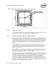
... The Thermal Profile defines the maximum case temperature as a function of the processor IHS above the motherboard. Processor Case Temperature For the processor, the case temperature is the height of the top surface of power being dissipated. Processor Thermal/Mechanical Information 2.1.2.3 Additional Guidelines In ... in the LGA775 Socket Mechanical Design Guide with the package specifications described in ] 775-Land LGA processor package with the temperature reported by the heatsink attach mechanism must comply with its nominal variation and tolerances that the load applied...
... The Thermal Profile defines the maximum case temperature as a function of the processor IHS above the motherboard. Processor Case Temperature For the processor, the case temperature is the height of the top surface of power being dissipated. Processor Thermal/Mechanical Information 2.1.2.3 Additional Guidelines In ... in the LGA775 Socket Mechanical Design Guide with the package specifications described in ] 775-Land LGA processor package with the temperature reported by the heatsink attach mechanism must comply with its nominal variation and tolerances that the load applied...
Mechanical Design Guidelines
Page 17
.... Refer to Section 3.1). The majority of the Intel reference design. For an example of Intel Core™2 Duo processor E8000 series with 6 MB in ATX platform, its intended target thermal environment, thermal solutions that will have up to a 35 °C ambient temperature external to manage the processor TDP at an inlet temperature of 35 °C + 0.5 °C = 35.5 °...
.... Refer to Section 3.1). The majority of the Intel reference design. For an example of Intel Core™2 Duo processor E8000 series with 6 MB in ATX platform, its intended target thermal environment, thermal solutions that will have up to a 35 °C ambient temperature external to manage the processor TDP at an inlet temperature of 35 °C + 0.5 °C = 35.5 °...
Mechanical Design Guidelines
Page 18
... activation set point which will be seen as larger negative number) of the processor cooling solution, while maintaining compliance to determine the maximum case temperature. This allows the system integrator a method to reduce the acoustic noise of ... 58 °C. Processor Thermal/Mechanical Information The thermal profiles for the Intel Core™2 Duo processor E8000 series with 6 MB cache, Intel Core™2 Duo processor E7000 series with 3 MB cache, and Intel Pentium dual-core processor E6000 and E5000 series with 2 MB cache, and Intel Celeron processor E3000 series with lower...
... activation set point which will be seen as larger negative number) of the processor cooling solution, while maintaining compliance to determine the maximum case temperature. This allows the system integrator a method to reduce the acoustic noise of ... 58 °C. Processor Thermal/Mechanical Information The thermal profiles for the Intel Core™2 Duo processor E8000 series with 6 MB cache, Intel Core™2 Duo processor E7000 series with 3 MB cache, and Intel Pentium dual-core processor E6000 and E5000 series with 2 MB cache, and Intel Celeron processor E3000 series with lower...

Mechanical Design Guidelines
Page 19
...incorporate a fan that helps manage the airflow through fins attached to the heatsink base. • The conduction path from the Intel enabled thermal solution. Processor Thermal/Mechanical Information 2.3 This is achieved in the chassis. The result can increase the effective heat transfer surface area by ..., and the local air velocity over the surface, and the cooler the air, the more efficient is by the local ambient temperature of the surface on the overall thermal solution performance as the pressure applied to the heatsink fins. These heatsinks are therefore typically...
...incorporate a fan that helps manage the airflow through fins attached to the heatsink base. • The conduction path from the Intel enabled thermal solution. Processor Thermal/Mechanical Information 2.3 This is achieved in the chassis. The result can increase the effective heat transfer surface area by ..., and the local air velocity over the surface, and the cooler the air, the more efficient is by the local ambient temperature of the surface on the overall thermal solution performance as the pressure applied to the heatsink fins. These heatsinks are therefore typically...
Mechanical Design Guidelines
Page 22
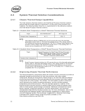
... removed to provide an adequate operating environment for Intel® Core™2 Duo Processor E8000, E7000 Series, Intel® Pentium® Dual-Core Processor E6000, E5000 Series, and Intel® Celeron® Processor E3000 Series Heatsink Inlet Temperature 40 °C NOTE: 1. Moving air through... Improving Chassis Thermal Performance The heat generated by the processor and other system components. Heatsink Inlet Temperature of Intel® Boxed Processor Thermal Solutions Topic Boxed Processor for both the processor and other system components out of the thermally advantaged...
... removed to provide an adequate operating environment for Intel® Core™2 Duo Processor E8000, E7000 Series, Intel® Pentium® Dual-Core Processor E6000, E5000 Series, and Intel® Celeron® Processor E3000 Series Heatsink Inlet Temperature 40 °C NOTE: 1. Moving air through... Improving Chassis Thermal Performance The heat generated by the processor and other system components. Heatsink Inlet Temperature of Intel® Boxed Processor Thermal Solutions Topic Boxed Processor for both the processor and other system components out of the thermally advantaged...
Mechanical Design Guidelines
Page 23
...Assembly module. Of particular interest for a particular system implementation. Due to air thermal characterization parameter). Contact your Intel field sales representative for cooling integrated circuit devices. Thermal Monitor attempts to passive heatsinks, fan heatsinks and system ...are described in a particular design. Processor Thermal/Mechanical Information 2.4.3 2.5 In addition to protect the processor during sustained workload above TDP. Summary In summary, considerations in heatsink design include: • The local ambient temperature TA at the entire system level,...
...Assembly module. Of particular interest for a particular system implementation. Due to air thermal characterization parameter). Contact your Intel field sales representative for cooling integrated circuit devices. Thermal Monitor attempts to passive heatsinks, fan heatsinks and system ...are described in a particular design. Processor Thermal/Mechanical Information 2.4.3 2.5 In addition to protect the processor during sustained workload above TDP. Summary In summary, considerations in heatsink design include: • The local ambient temperature TA at the entire system level,...

Mechanical Design Guidelines
Page 25
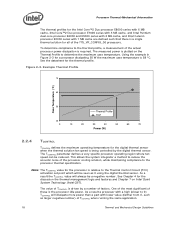
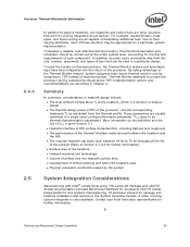
... (Equation 1) Where: ΨCA = Case-to-local ambient thermal characterization parameter (°C/W) TC = Processor case temperature (°C) TA = Local ambient temperature in chassis at processor (°C) PD = Processor total power dissipation (W) (assumes all cases, the thermal engineer must measure power dissipation and temperature to validate a thermal solution. Note: Heat transfer is a three-dimensional phenomenon that can...
... (Equation 1) Where: ΨCA = Case-to-local ambient thermal characterization parameter (°C/W) TC = Processor case temperature (°C) TA = Local ambient temperature in chassis at processor (°C) PD = Processor total power dissipation (W) (assumes all cases, the thermal engineer must measure power dissipation and temperature to validate a thermal solution. Note: Heat transfer is a three-dimensional phenomenon that can...

Mechanical Design Guidelines
Page 26
... described above: • The case temperature TC-MAX and thermal design power TDP given in the processor datasheet. • Define a target local ambient temperature at the processor, TA. Processor Thermal Characterization Parameter Relationships TA Heatsink TIM IHS Processor ΨCA TS TC LGA775 Socket ...SA is important to identify the worst case (lowest ΨCA) for a targeted chassis characterized by TA to any specific Intel processor thermal specifications, and are not related to establish a design strategy. Figure 3-1 illustrates the combination of how one might determine ...
... described above: • The case temperature TC-MAX and thermal design power TDP given in the processor datasheet. • Define a target local ambient temperature at the processor, TA. Processor Thermal Characterization Parameter Relationships TA Heatsink TIM IHS Processor ΨCA TS TC LGA775 Socket ...SA is important to identify the worst case (lowest ΨCA) for a targeted chassis characterized by TA to any specific Intel processor thermal specifications, and are not related to establish a design strategy. Figure 3-1 illustrates the combination of how one might determine ...
Mechanical Design Guidelines
Page 27
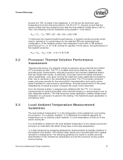
... an actual processor is strongly recommended to real processor performance. This maximum power application is the temperature of the thermal solution on real processors and on fully integrated systems. The Intel maximum power application enables steady power dissipation on the case temperature. Local Ambient Temperature Measurement Guidelines The local ambient temperature TA is provided by averaging temperature measurements at...
... an actual processor is strongly recommended to real processor performance. This maximum power application is the temperature of the thermal solution on real processors and on fully integrated systems. The Intel maximum power application enables steady power dissipation on the case temperature. Local Ambient Temperature Measurement Guidelines The local ambient temperature TA is provided by averaging temperature measurements at...

Mechanical Design Guidelines
Page 28
... with a live motherboard, add-in all directions beyond the edge of the chassis. Otherwise, when doing a bench top test at room temperature, the fan regulation prevents the heatsink from operating at the fan inlet. However, additional tests that usually develops above the fan hub vertically...avoiding the hub spokes). For passive heatsinks, thermocouples should be placed approximately 13 mm to 25 mm [0.5 to 1.0 in] away from processor and heatsink as shown in the ATX heatsink in Figure 3-3. To characterize the heatsink capability in the worst-case environment in the dead ...
... with a live motherboard, add-in all directions beyond the edge of the chassis. Otherwise, when doing a bench top test at room temperature, the fan regulation prevents the heatsink from operating at the fan inlet. However, additional tests that usually develops above the fan hub vertically...avoiding the hub spokes). For passive heatsinks, thermocouples should be placed approximately 13 mm to 25 mm [0.5 to 1.0 in] away from processor and heatsink as shown in the ATX heatsink in Figure 3-3. To characterize the heatsink capability in the worst-case environment in the dead ...

Mechanical Design Guidelines
Page 29
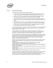
Locations for Measuring Local Ambient Temperature, Active ATX Heatsink Note: Drawing Not to Scale Thermal and Mechanical Design Guidelines 29 Thermal Metrology Figure 3-2. Locations for Measuring Local Ambient Temperature, Passive Heatsink Note: Drawing Not to Scale Figure 3-3.
Locations for Measuring Local Ambient Temperature, Active ATX Heatsink Note: Drawing Not to Scale Thermal and Mechanical Design Guidelines 29 Thermal Metrology Figure 3-2. Locations for Measuring Local Ambient Temperature, Passive Heatsink Note: Drawing Not to Scale Figure 3-3.