Product Guide
Page 7
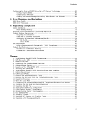
...21. Installing a PCI Express x16 Card 43 vii Installing the I/O Shield 29 8. LAN Connector LEDs 16 3. Lift the Socket Lever 31 10. Remove the Processor from the Protective Processor Cover 33 13. HDD Activity LED 17 4. Lift the Load ...40 23. Installing the ICH Heat Sink Decorative Cover 36 17. Dual Channel Memory Configuration 38 20. Intel Desktop Board DX58SO Components 11 2. Onboard Power Button 24 6. Intel Desktop Board DX58SO Mounting Screw Hole Locations 30 9. Contents Configuring for External RAID Using Marvell* Storage Technology 69 Configuring the...
...21. Installing a PCI Express x16 Card 43 vii Installing the I/O Shield 29 8. LAN Connector LEDs 16 3. Lift the Socket Lever 31 10. Remove the Processor from the Protective Processor Cover 33 13. HDD Activity LED 17 4. Lift the Load ...40 23. Installing the ICH Heat Sink Decorative Cover 36 17. Dual Channel Memory Configuration 38 20. Intel Desktop Board DX58SO Components 11 2. Onboard Power Button 24 6. Intel Desktop Board DX58SO Mounting Screw Hole Locations 30 9. Contents Configuring for External RAID Using Marvell* Storage Technology 69 Configuring the...
Product Guide
Page 9
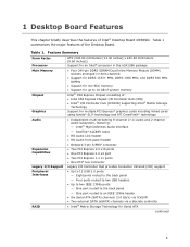
... Intel® Desktop Board DX58SO. Feature Summary Form Factor Processor Main Memory Chipset Graphics Audio Expansion Capabilities Legacy I/O Support Peripheral Interfaces RAID ATX (304.80 millimeters [12.00 inches] x 243.84 millimeters [9.60 inches]) Support for an Intel® processor in the LGA1366 package • Four 240-pin DDR3 SDRAM Dual Inline Memory Module (DIMM) sockets...
... Intel® Desktop Board DX58SO. Feature Summary Form Factor Processor Main Memory Chipset Graphics Audio Expansion Capabilities Legacy I/O Support Peripheral Interfaces RAID ATX (304.80 millimeters [12.00 inches] x 243.84 millimeters [9.60 inches]) Support for an Intel® processor in the LGA1366 package • Four 240-pin DDR3 SDRAM Dual Inline Memory Module (DIMM) sockets...
Product Guide
Page 13
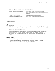
... processor, page 31 in damage to the Desktop Board through the LGA1366 socket. Related Links: Go to the following links for more information about : • Intel Desktop Board DX58SO http://www.intel.com/design/motherbd http://support.intel.com/support/motherboards/ desktop • Supported processors http://processormatch.intel.com • Audio software and utilities http://www.intel.com/design/motherbd • LAN software...
... processor, page 31 in damage to the Desktop Board through the LGA1366 socket. Related Links: Go to the following links for more information about : • Intel Desktop Board DX58SO http://www.intel.com/design/motherbd http://support.intel.com/support/motherboards/ desktop • Supported processors http://processormatch.intel.com • Audio software and utilities http://www.intel.com/design/motherbd • LAN software...

Product Guide
Page 22
... the Technical Product Specification at the memory module sockets and the PCI bus connectors. Intel Desktop Board DX58SO Product Guide The Desktop Board supports the PCI Bus Power Management Interface Specification. The Desktop Board's standby power indicator, shown in power management and can be off and the standby power indicator is still present at http://support.intel.com/support/motherboards/desktop/ 22
... the Technical Product Specification at the memory module sockets and the PCI bus connectors. Intel Desktop Board DX58SO Product Guide The Desktop Board supports the PCI Bus Power Management Interface Specification. The Desktop Board's standby power indicator, shown in power management and can be off and the standby power indicator is still present at http://support.intel.com/support/motherboards/desktop/ 22

Product Guide
Page 31
... standby power LED should not be lit (see Figure 4 on page 27. 2. Open the socket lever by unplugging the power cord from the socket (Figure 9, A and B). Failure to install the processor on the Desktop Board are given below. Lift the Socket Lever 31 Installing a Processor CAUTION Before installing or removing a processor, make sure the AC...
... standby power LED should not be lit (see Figure 4 on page 27. 2. Open the socket lever by unplugging the power cord from the socket (Figure 9, A and B). Failure to install the processor on the Desktop Board are given below. Lift the Socket Lever 31 Installing a Processor CAUTION Before installing or removing a processor, make sure the AC...

Product Guide
Page 32
Lift the load plate as shown in Figure 10. Figure 11. Do not discard the protective socket cover. Remove the Protective Socket Cover 32 Intel Desktop Board DX58SO Product Guide 3. Lift the Load Plate 4. Remove the protective socket cover from the socket. Be sure to always replace the cover if the processor is removed from the socket by grasping the cover and lifting straight up as shown in Figure 11. Do not touch the socket contacts. Figure 10.
Lift the load plate as shown in Figure 10. Figure 11. Do not discard the protective socket cover. Remove the Protective Socket Cover 32 Intel Desktop Board DX58SO Product Guide 3. Lift the Load Plate 4. Remove the protective socket cover from the socket. Be sure to always replace the cover if the processor is removed from the socket by grasping the cover and lifting straight up as shown in Figure 11. Do not touch the socket contacts. Figure 10.
Product Guide
Page 33
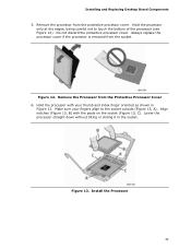
... the Processor from the socket. Make sure your thumb and index finger oriented as shown in the socket. Align notches (Figure 13, B) with your fingers align to touch the bottom of the processor (see Figure 12). Installing and Replacing Desktop Board Components 5. Hold the processor... only at the edges, being careful not to the socket cutouts (Figure 13, A). Do not discard the protective processor cover. Lower the processor straight...
... the Processor from the socket. Make sure your thumb and index finger oriented as shown in the socket. Align notches (Figure 13, B) with your fingers align to touch the bottom of the processor (see Figure 12). Installing and Replacing Desktop Board Components 5. Hold the processor... only at the edges, being careful not to the socket cutouts (Figure 13, A). Do not discard the protective processor cover. Lower the processor straight...

Product Guide
Page 34
Intel Desktop Board DX58SO Product Guide 7. Pressing down on the load plate (Figure 14, A), close and engage the socket lever (Figure 14, B). Figure 14. Close the Load Plate 34
Intel Desktop Board DX58SO Product Guide 7. Pressing down on the load plate (Figure 14, A), close and engage the socket lever (Figure 14, B). Figure 14. Close the Load Plate 34

Product Guide
Page 38
... A, DIMM 1 may result in three channels (A, B, and C). Figure 19. Channel A shares two sockets (DIMM 0 and DIMM 1) and Channels B and C have one socket each. Dual Channel Memory Configuration 38 Intel Desktop Board DX58SO Product Guide Installing and Removing Memory Intel Desktop board DX58SO has four 240-pin DDR3 DIMM sockets arranged in less than optimal memory performance. Optimal memory performance can be...
... A, DIMM 1 may result in three channels (A, B, and C). Figure 19. Channel A shares two sockets (DIMM 0 and DIMM 1) and Channels B and C have one socket each. Dual Channel Memory Configuration 38 Intel Desktop Board DX58SO Product Guide Installing and Removing Memory Intel Desktop board DX58SO has four 240-pin DDR3 DIMM sockets arranged in less than optimal memory performance. Optimal memory performance can be...

Product Guide
Page 40
...Make sure the clips at the bottom edge of the DIMM until the retaining clips snap into the socket. 8. Position the DIMM above the socket. Remove the computer's cover and locate the DIMM sockets (see inset in Figure 22). 7. Holding the DIMM by the edges, remove it from its anti...the computer's cover and reconnect the AC power cord. 40 Insert the bottom edge of the DIMM socket(s) are firmly in place. 9. Intel Desktop Board DX58SO Product Guide NOTE Using a DIMM with the keys in the socket (see Figure 22). Make sure the clips are pushed outward to the computer. To install a ...
...Make sure the clips at the bottom edge of the DIMM until the retaining clips snap into the socket. 8. Position the DIMM above the socket. Remove the computer's cover and locate the DIMM sockets (see inset in Figure 22). 7. Holding the DIMM by the edges, remove it from its anti...the computer's cover and reconnect the AC power cord. 40 Insert the bottom edge of the DIMM socket(s) are firmly in place. 9. Intel Desktop Board DX58SO Product Guide NOTE Using a DIMM with the keys in the socket (see Figure 22). Make sure the clips are pushed outward to the computer. To install a ...

Product Guide
Page 41
... "Before You Begin" on page 27. 2. Turn off the computer. 3. Turn off all peripheral devices connected to reach the DIMM sockets. 8. The DIMM pops out of the DIMM socket. Installing and Replacing Desktop Board Components Removing DIMMs To remove a DIMM, follow these steps: 1. Observe the precautions in an anti-static package. 7. Replace the computer... the computer's cover. 5. Reinstall and reconnect any parts you removed or disconnected to the computer. Gently spread the retaining clips at each end of the socket. 6.
... "Before You Begin" on page 27. 2. Turn off the computer. 3. Turn off all peripheral devices connected to reach the DIMM sockets. 8. The DIMM pops out of the DIMM socket. Installing and Replacing Desktop Board Components Removing DIMMs To remove a DIMM, follow these steps: 1. Observe the precautions in an anti-static package. 7. Replace the computer... the computer's cover. 5. Reinstall and reconnect any parts you removed or disconnected to the computer. Gently spread the retaining clips at each end of the socket. 6.
Product Guide
Page 57
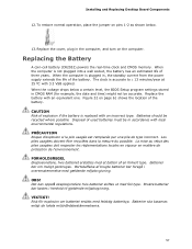
To restore normal operation, place the jumper on the computer. When the computer is not plugged into a wall socket, the battery has an estimated life of explosion if the battery is replaced with local environmental regulations. Batteries should be in , the standby current... drops below a certain level, the BIOS Setup program settings stored in the computer, and turn on pins 1-2 as shown below. 13. Installing and Replacing Desktop Board Components 12. When the computer is accurate to ± 13 minutes/year at 25 ºC with an equivalent one. Replace the battery with 3.3 VSB ...
To restore normal operation, place the jumper on the computer. When the computer is not plugged into a wall socket, the battery has an estimated life of explosion if the battery is replaced with local environmental regulations. Batteries should be in , the standby current... drops below a certain level, the BIOS Setup program settings stored in the computer, and turn on pins 1-2 as shown below. 13. Installing and Replacing Desktop Board Components 12. When the computer is accurate to ± 13 minutes/year at 25 ºC with an equivalent one. Replace the battery with 3.3 VSB ...


