Product Guide
Page 5
Contents 1 Desktop Board Features Supported Operating Systems 10 Desktop Board Components 11 Processor ...13 Main Memory...14 Intel® X58 Express Chipset 15 Audio Subsystem 15 LAN Subsystem 16 USB 2.0 Support 17 Serial ATA...17 Legacy I/O ...18 Expandability...18 ...Capable 23 Onboard Power Button 24 Onboard VR and CPU LEDs 25 Speaker...25 Battery ...25 Real-Time Clock 25 2 Installing and Replacing Desktop Board Components Before You Begin 27 Installation Precautions 28 Prevent Power Supply Overload 28 Observe Safety and Regulatory Requirements 28 Installing the I/O Shield 29 ...
Contents 1 Desktop Board Features Supported Operating Systems 10 Desktop Board Components 11 Processor ...13 Main Memory...14 Intel® X58 Express Chipset 15 Audio Subsystem 15 LAN Subsystem 16 USB 2.0 Support 17 Serial ATA...17 Legacy I/O ...18 Expandability...18 ...Capable 23 Onboard Power Button 24 Onboard VR and CPU LEDs 25 Speaker...25 Battery ...25 Real-Time Clock 25 2 Installing and Replacing Desktop Board Components Before You Begin 27 Installation Precautions 28 Prevent Power Supply Overload 28 Observe Safety and Regulatory Requirements 28 Installing the I/O Shield 29 ...
Product Guide
Page 6
Intel Desktop Board DX58SO Product Guide Installing and Removing a Processor 31 Installing a Processor 31 Installing the Processor Fan Heat Sink 35 Connecting the Processor Fan Heat Sink Cable 35 Removing the Processor 36 Installing the ICH Heat Sink Decorative Cover (Optional 36 Installing the IOH Cooling Fan (Optional 37 ...Setting the BIOS Configuration Jumper 55 Clearing Passwords 56 Replacing the Battery 57 3 Updating the BIOS Updating the BIOS with the Intel® Express BIOS Update Utility 63 Updating the BIOS with the ISO Image BIOS Update File or the Iflash Memory Update ...
Intel Desktop Board DX58SO Product Guide Installing and Removing a Processor 31 Installing a Processor 31 Installing the Processor Fan Heat Sink 35 Connecting the Processor Fan Heat Sink Cable 35 Removing the Processor 36 Installing the ICH Heat Sink Decorative Cover (Optional 36 Installing the IOH Cooling Fan (Optional 37 ...Setting the BIOS Configuration Jumper 55 Clearing Passwords 56 Replacing the Battery 57 3 Updating the BIOS Updating the BIOS with the Intel® Express BIOS Update Utility 63 Updating the BIOS with the ISO Image BIOS Update File or the Iflash Memory Update ...
Product Guide
Page 7
... Activity LED 17 4. Location of the VR and CPU LEDs 25 7. Connecting the Processor Fan Heat Sink Cable to the Processor Fan Header ..........35 16. Triple Channel Memory Configuration 38 19. Single Channel Memory Configuration 39 21. Lift the Load Plate 32 11. Install the Processor 33 14. Intel Desktop Board DX58SO Mounting Screw Hole Locations 30 9.
... Activity LED 17 4. Location of the VR and CPU LEDs 25 7. Connecting the Processor Fan Heat Sink Cable to the Processor Fan Header ..........35 16. Triple Channel Memory Configuration 38 19. Single Channel Memory Configuration 39 21. Lift the Load Plate 32 11. Install the Processor 33 14. Intel Desktop Board DX58SO Mounting Screw Hole Locations 30 9.
Product Guide
Page 9
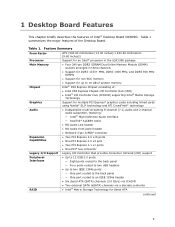
...800 MHz DIMMs • Support for non-ECC memory • Support for Serial ATA continued 9 Feature Summary Form Factor Processor Main Memory Chipset Graphics Audio Expansion Capabilities Legacy I /O Controller that provides Consumer Infrared (CIR) support • Up ... external SATA (eSATA) channels via a discrete controller • Intel® Matrix Storage Technology for up to 16 GB of system memory Intel® X58 Express Chipset consisting of the Desktop Board. 1 Desktop Board Features This chapter briefly describes the features of Intel® Desktop Board DX58SO. Table 1.
...800 MHz DIMMs • Support for non-ECC memory • Support for Serial ATA continued 9 Feature Summary Form Factor Processor Main Memory Chipset Graphics Audio Expansion Capabilities Legacy I /O Controller that provides Consumer Infrared (CIR) support • Up ... external SATA (eSATA) channels via a discrete controller • Intel® Matrix Storage Technology for up to 16 GB of system memory Intel® X58 Express Chipset consisting of the Desktop Board. 1 Desktop Board Features This chapter briefly describes the features of Intel® Desktop Board DX58SO. Table 1.
Product Guide
Page 13
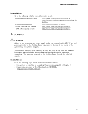
Intel Desktop Board DX58SO supports an Intel processor in Chapter 2 • Supported processors for Intel Desktop Board DX58SO, http://processormatch.intel.com 13 The processor connects to the Desktop Board through the LGA1366 socket. Processors are not included with the Desktop Board and must be purchased separately. Related Links: Go to the following links for more information about : • Intel Desktop Board DX58SO http://www.intel.com/design/motherbd http://support.intel.com/support/motherboards/ desktop •...
Intel Desktop Board DX58SO supports an Intel processor in Chapter 2 • Supported processors for Intel Desktop Board DX58SO, http://processormatch.intel.com 13 The processor connects to the Desktop Board through the LGA1366 socket. Processors are not included with the Desktop Board and must be purchased separately. Related Links: Go to the following links for more information about : • Intel Desktop Board DX58SO http://www.intel.com/design/motherbd http://support.intel.com/support/motherboards/ desktop •...
Product Guide
Page 14
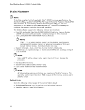
... 1.65 V may damage the processor. • Non-ECC DDR3 memory • Serial Presence Detect (SPD) memory only • Up to 16 GB maximum total system memory NOTE 32-bit operating systems are limited to this desktop board requires compatible XMP-enabled memory or... about: • SDRAM specifications, http://www.intel.com/technology/memory/ • Installing memory, page 38 in Chapter 2 14 Intel Desktop Board DX58SO Product Guide Main Memory NOTE To be fully compliant with all applicable Intel ® SDRAM memory specifications, the board should be populated with a voltage rating higher...
... 1.65 V may damage the processor. • Non-ECC DDR3 memory • Serial Presence Detect (SPD) memory only • Up to 16 GB maximum total system memory NOTE 32-bit operating systems are limited to this desktop board requires compatible XMP-enabled memory or... about: • SDRAM specifications, http://www.intel.com/technology/memory/ • Installing memory, page 38 in Chapter 2 14 Intel Desktop Board DX58SO Product Guide Main Memory NOTE To be fully compliant with all applicable Intel ® SDRAM memory specifications, the board should be populated with a voltage rating higher...

Product Guide
Page 15
Desktop Board Features Intel® X58 Express Chipset The Intel X58 Express Chipset consists of the following devices: • Intel X58 Express Chipset I/O Hub (IOH) • Intel 82801IJR I/O Controller Hub (ICH10R) The IOH provides interfaces to the following link or pages for more information about : • Audio drivers and utilities http://support.intel.com/support/motherboards/desktop/ • The location...
Desktop Board Features Intel® X58 Express Chipset The Intel X58 Express Chipset consists of the following devices: • Intel X58 Express Chipset I/O Hub (IOH) • Intel 82801IJR I/O Controller Hub (ICH10R) The IOH provides interfaces to the following link or pages for more information about : • Audio drivers and utilities http://support.intel.com/support/motherboards/desktop/ • The location...

Product Guide
Page 19
... boots without asking for a password. Hardware Management The hardware management features of Intel Desktop Board DX58SO enable the board to view and change all onboard fans, that can adjust fan speed 19 The board has several hardware management features including the following restrictions: • The supervisor password... utility in the BIOS automatically detects and configures the resources (IRQs, DMA channels, and I/O space) for that add-in the processor • Thermally monitored closed-loop fan control, for all Setup options. If only the supervisor password is set , you must ...
... boots without asking for a password. Hardware Management The hardware management features of Intel Desktop Board DX58SO enable the board to view and change all onboard fans, that can adjust fan speed 19 The board has several hardware management features including the following restrictions: • The supervisor password... utility in the BIOS automatically detects and configures the resources (IRQs, DMA channels, and I/O space) for that add-in the processor • Thermally monitored closed-loop fan control, for all Setup options. If only the supervisor password is set , you must ...
Product Guide
Page 20
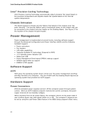
... a chassis security feature that provides full ACPI support. The use of ACPI with the Desktop Board requires an operating system that detects if the chassis cover has been removed. Hardware Support Power Connectors ATX12V-compliant ...failure, the computer returns to the power state it was interrupted (either on the Desktop Board. Intel Desktop Board DX58SO Product Guide Intel® Precision Cooling Technology Intel Precision Cooling Technology automatically adjust processor fan speed based on the processor temperature and adjusts chassis fan speeds based on the chassis that can be set ...
... a chassis security feature that provides full ACPI support. The use of ACPI with the Desktop Board requires an operating system that detects if the chassis cover has been removed. Hardware Support Power Connectors ATX12V-compliant ...failure, the computer returns to the power state it was interrupted (either on the Desktop Board. Intel Desktop Board DX58SO Product Guide Intel® Precision Cooling Technology Intel Precision Cooling Technology automatically adjust processor fan speed based on the processor temperature and adjusts chassis fan speeds based on the chassis that can be set ...

Product Guide
Page 21
The Desktop Board has a 4-pin processor fan header, one 4-pin and two 3-pin chassis fan headers, and one 3-pin IOH fan header. LAN Wake Capabilities CAUTION For LAN wake capabilities, the 5 V ... for the location of delivering adequate +5 V standby current. Failure to be able to provide enough standby current to provide adequate standby current when using this Desktop Board must be capable of the power connectors. The LAN subsystem monitors network traffic and upon detecting a Magic Packet* frame, it asserts a wake-up signal that...
The Desktop Board has a 4-pin processor fan header, one 4-pin and two 3-pin chassis fan headers, and one 3-pin IOH fan header. LAN Wake Capabilities CAUTION For LAN wake capabilities, the 5 V ... for the location of delivering adequate +5 V standby current. Failure to be able to provide enough standby current to provide adequate standby current when using this Desktop Board must be capable of the power connectors. The LAN subsystem monitors network traffic and upon detecting a Magic Packet* frame, it asserts a wake-up signal that...

Product Guide
Page 25
... is turned off . Real-Time Clock The Desktop Board has a time-of the board's beep codes. Refer to replace the battery. Desktop Board Features Onboard VR and CPU LEDs The Desktop Board contains the following two LEDs (see Figure 6) that indicate the status of the board's voltage regulation circuitry and the processor: • The CPU LED (Figure 6, A) indicates an...
... is turned off . Real-Time Clock The Desktop Board has a time-of the board's beep codes. Refer to replace the battery. Desktop Board Features Onboard VR and CPU LEDs The Desktop Board contains the following two LEDs (see Figure 6) that indicate the status of the board's voltage regulation circuitry and the processor: • The CPU LED (Figure 6, A) indicates an...
Product Guide
Page 27
...components. Follow these guidelines before you open the computer or perform any of the computer chassis. 27 Some circuitry on the board can continue to disconnect power, telecommunications links, networks, or modems before you begin: • Always follow the steps in...ESD workstation using and modifying electronic equipment. 2 Installing and Replacing Desktop Board Components This chapter tells you how to: • Install the I/O shield • Install and remove the Desktop Board • Install and remove a processor • Install the ICH heat sink decorative cover • Install...
...components. Follow these guidelines before you open the computer or perform any of the computer chassis. 27 Some circuitry on the board can continue to disconnect power, telecommunications links, networks, or modems before you begin: • Always follow the steps in...ESD workstation using and modifying electronic equipment. 2 Installing and Replacing Desktop Board Components This chapter tells you how to: • Install the I/O shield • Install and remove the Desktop Board • Install and remove a processor • Install the ICH heat sink decorative cover • Install...

Product Guide
Page 28
...; Rough edges and sharp corners on the chassis • Hot components (such as processors, voltage regulators, and heat sinks) • Damage to qualified technical personnel. If the instructions for associated modules, contact the supplier to Appendix B. 28 Intel Desktop Board DX58SO Product Guide Installation Precautions When you can ensure that your safety risk and the...
...; Rough edges and sharp corners on the chassis • Hot components (such as processors, voltage regulators, and heat sinks) • Damage to qualified technical personnel. If the instructions for associated modules, contact the supplier to Appendix B. 28 Intel Desktop Board DX58SO Product Guide Installation Precautions When you can ensure that your safety risk and the...

Product Guide
Page 31
Installing and Replacing Desktop Board Components Installing and Removing a Processor Instructions on how to do so could damage the processor and the board. Lift the Socket Lever 31 Failure to install the processor on the Desktop Board are given below. Observe the precautions in "Before You Begin" on page 22). the standby power LED should not be lit (see...
Installing and Replacing Desktop Board Components Installing and Removing a Processor Instructions on how to do so could damage the processor and the board. Lift the Socket Lever 31 Failure to install the processor on the Desktop Board are given below. Observe the precautions in "Before You Begin" on page 22). the standby power LED should not be lit (see...

Product Guide
Page 32
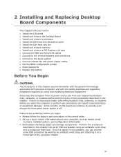
Remove the protective socket cover from the socket. Remove the Protective Socket Cover 32 Figure 10. Do not touch the socket contacts. Lift the Load Plate 4. Do not discard the protective socket cover. Lift the load plate as shown in Figure 10. Be sure to always replace the cover if the processor is removed from the socket by grasping the cover and lifting straight up as shown in Figure 11. Intel Desktop Board DX58SO Product Guide 3. Figure 11.
Remove the protective socket cover from the socket. Remove the Protective Socket Cover 32 Figure 10. Do not touch the socket contacts. Lift the Load Plate 4. Do not discard the protective socket cover. Lift the load plate as shown in Figure 10. Be sure to always replace the cover if the processor is removed from the socket by grasping the cover and lifting straight up as shown in Figure 11. Intel Desktop Board DX58SO Product Guide 3. Figure 11.
Product Guide
Page 33
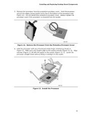
...index finger oriented as shown in the socket. Install the Processor 33 Remove the processor from the socket. Lower the processor straight down without tilting or sliding it in Figure 13. Hold the processor only at the edges, being careful not to the socket...the Processor from the Protective Processor Cover 6. Align notches (Figure 13, B) with your fingers align to touch the bottom of the processor (see Figure 12). Do not discard the protective processor cover. Hold the processor with the posts on the socket (Figure 13, C). Installing and Replacing Desktop Board Components...
...index finger oriented as shown in the socket. Install the Processor 33 Remove the processor from the socket. Lower the processor straight down without tilting or sliding it in Figure 13. Hold the processor only at the edges, being careful not to the socket...the Processor from the Protective Processor Cover 6. Align notches (Figure 13, B) with your fingers align to touch the bottom of the processor (see Figure 12). Do not discard the protective processor cover. Hold the processor with the posts on the socket (Figure 13, C). Installing and Replacing Desktop Board Components...

Product Guide
Page 35
... Heat Sink Cable to the 4-pin processor fan header (see Figure 15). A fan with a 3-pin connector cannot use the onboard fan control, the fan will always operate at full speed. Figure 15. ... Cable Connect the processor fan heat sink cable to the Processor Fan Header 35 For instructions on how to attach the processor fan heat sink to the Desktop Board, refer to the boxed processor manual or boxed thermal solution manual. Installing and Replacing Desktop Board Components Installing the Processor Fan Heat Sink Intel Desktop Board DX58SO has mounting holes for a processor fan heat sink...
... Heat Sink Cable to the 4-pin processor fan header (see Figure 15). A fan with a 3-pin connector cannot use the onboard fan control, the fan will always operate at full speed. Figure 15. ... Cable Connect the processor fan heat sink cable to the Processor Fan Header 35 For instructions on how to attach the processor fan heat sink to the Desktop Board, refer to the boxed processor manual or boxed thermal solution manual. Installing and Replacing Desktop Board Components Installing the Processor Fan Heat Sink Intel Desktop Board DX58SO has mounting holes for a processor fan heat sink...

Product Guide
Page 36
... ensure that the adhesive adheres to the processor installation manual. Figure 16. Remove the paper covering the adhesive strip on the bottom of the heat sink cover (Figure 16, A). 3. Intel Desktop Board DX58SO Product Guide Removing the Processor For instructions on how to remove the processor fan heat sink and processor, refer to the heat sink. Installing the...
... ensure that the adhesive adheres to the processor installation manual. Figure 16. Remove the paper covering the adhesive strip on the bottom of the heat sink cover (Figure 16, A). 3. Intel Desktop Board DX58SO Product Guide Removing the Processor For instructions on how to remove the processor fan heat sink and processor, refer to the heat sink. Installing the...

Product Guide
Page 40
... pushed outward to the computer. Make sure the clips at the bottom edge of the DIMM until the retaining clips snap into the socket. 8. Intel Desktop Board DX58SO Product Guide NOTE Using a DIMM with the keys in the socket (see Figure 22). Installing a DIMM 4. Align the small notch at either ...socket(s) are firmly in "Before You Begin" on the top edge of the DIMM with a voltage rating higher than 1.65 V may damage the processor. Observe the precautions in place. 9. Replace the computer's cover and reconnect the AC power cord. 40 When the DIMM is inserted, push down ...
... pushed outward to the computer. Make sure the clips at the bottom edge of the DIMM until the retaining clips snap into the socket. 8. Intel Desktop Board DX58SO Product Guide NOTE Using a DIMM with the keys in the socket (see Figure 22). Installing a DIMM 4. Align the small notch at either ...socket(s) are firmly in "Before You Begin" on the top edge of the DIMM with a voltage rating higher than 1.65 V may damage the processor. Observe the precautions in place. 9. Replace the computer's cover and reconnect the AC power cord. 40 When the DIMM is inserted, push down ...

Product Guide
Page 55
...unplug the power cord from the computer before moving the jumper. Connect the 12 V processor core voltage power supply cable to be done in unreliable computer operation. Location of the Desktop Board's BIOS configuration jumper block. Observe the precautions in "Before You Begin" on may... result in the BIOS Setup program. Table 14 shows the jumper settings for the BIOS Setup program modes. 55 Installing and Replacing Desktop Board Components 1.
...unplug the power cord from the computer before moving the jumper. Connect the 12 V processor core voltage power supply cable to be done in unreliable computer operation. Location of the Desktop Board's BIOS configuration jumper block. Observe the precautions in "Before You Begin" on may... result in the BIOS Setup program. Table 14 shows the jumper settings for the BIOS Setup program modes. 55 Installing and Replacing Desktop Board Components 1.


