Product Guide
Page 6
Intel Desktop Board DX58SO Product Guide Installing and Removing a Processor 31 Installing a Processor 31 Installing the ...-in Card 44 Connecting the Serial ATA (SATA) Cables 45 Connecting to the Internal Headers and Connectors 46 Front Panel Audio Header 47 HD Audio Link Header 47 Consumer IR (CIR) Headers 48 Chassis Intrusion Header 49 IEEE 1394a ...Header 49 USB 2.0 Headers 50 Front Panel Header 50 Alternate Front Panel Power LED Header 51 S/PDIF Connector 51 Connecting to the Audio System 52 Connecting Chassis Fan and ...
Intel Desktop Board DX58SO Product Guide Installing and Removing a Processor 31 Installing a Processor 31 Installing the ...-in Card 44 Connecting the Serial ATA (SATA) Cables 45 Connecting to the Internal Headers and Connectors 46 Front Panel Audio Header 47 HD Audio Link Header 47 Consumer IR (CIR) Headers 48 Chassis Intrusion Header 49 IEEE 1394a ...Header 49 USB 2.0 Headers 50 Front Panel Header 50 Alternate Front Panel Power LED Header 51 S/PDIF Connector 51 Connecting to the Audio System 52 Connecting Chassis Fan and ...
Product Guide
Page 8
...73 18. USB 2.0 Header Signal Names 50 11. Intel Desktop Board DX58SO China RoHS Material Self Declaration Table 81 Tables 1. Front Panel Header Signal Names 50 12. Lead-Free Second Level Interconnect Marks 79 19. Front Panel CIR Receiver (Input) Header Signal Names 48 7. IEEE...of the BIOS Configuration Jumper Block 55 32. Chassis Intrusion Header Signal Names 49 9. Alternate Front Panel Power LED Header Signal Names 51 13. Intel Desktop Board DX58SO Product Guide 25. Connecting Power Supply Cables 54 31. Jumper Settings for the BIOS Setup Program Modes...
...73 18. USB 2.0 Header Signal Names 50 11. Intel Desktop Board DX58SO China RoHS Material Self Declaration Table 81 Tables 1. Front Panel Header Signal Names 50 12. Lead-Free Second Level Interconnect Marks 79 19. Front Panel CIR Receiver (Input) Header Signal Names 48 7. IEEE...of the BIOS Configuration Jumper Block 55 32. Chassis Intrusion Header Signal Names 49 9. Alternate Front Panel Power LED Header Signal Names 51 13. Intel Desktop Board DX58SO Product Guide 25. Connecting Power Supply Cables 54 31. Jumper Settings for the BIOS Setup Program Modes...
Product Guide
Page 9
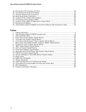
...Intel® Desktop Board DX58SO. 1 Desktop Board Features This chapter briefly describes the features of the Desktop Board. Feature Summary Form Factor Processor Main Memory Chipset Graphics Audio Expansion Capabilities Legacy I/O Support Peripheral Interfaces RAID ATX (304.80 millimeters [12.00 inches] x 243.84 millimeters [9.60 inches]) Support for an Intel...provides Consumer Infrared (CIR) support • Up to 12 USB 2.0 ports: ― Eight ports routed to the back panel ― Four ports routed to two USB headers • Up to two IEEE 1394a ports: ― One port routed to the back...
...Intel® Desktop Board DX58SO. 1 Desktop Board Features This chapter briefly describes the features of the Desktop Board. Feature Summary Form Factor Processor Main Memory Chipset Graphics Audio Expansion Capabilities Legacy I/O Support Peripheral Interfaces RAID ATX (304.80 millimeters [12.00 inches] x 243.84 millimeters [9.60 inches]) Support for an Intel...provides Consumer Infrared (CIR) support • Up to 12 USB 2.0 ports: ― Eight ports routed to the back panel ― Four ports routed to two USB headers • Up to two IEEE 1394a ports: ― One port routed to the back...
Product Guide
Page 10
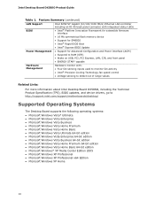
...panel • ENERGY STAR* capable Hardware Management Hardware monitor with: • Four fan sensing inputs used to monitor fan activity • Intel® Precision Cooling Technology fan speed control • Voltage sensing to detect out of range values Related Links: For more information about Intel Desktop Board DX58SO..., including the Technical Product Specification (TPS), BIOS updates, and device drivers, go to http://support.intel.com/support/motherboards/desktop/ Supported Operating Systems The Desktop Board supports the following ...
...panel • ENERGY STAR* capable Hardware Management Hardware monitor with: • Four fan sensing inputs used to monitor fan activity • Intel® Precision Cooling Technology fan speed control • Voltage sensing to detect out of range values Related Links: For more information about Intel Desktop Board DX58SO..., including the Technical Product Specification (TPS), BIOS updates, and device drivers, go to http://support.intel.com/support/motherboards/desktop/ Supported Operating Systems The Desktop Board supports the following ...

Product Guide
Page 15
Desktop Board Features Intel® X58 Express Chipset The Intel X58 Express Chipset consists of the following link or pages for more information about : • Audio drivers and utilities http://support.intel.com/support/motherboards/desktop/ • The location of 95 dB • Independent multi-streaming 8-channel (7.1) audio (using the back panel audio connectors) and 2-channel audio (using the...
Desktop Board Features Intel® X58 Express Chipset The Intel X58 Express Chipset consists of the following link or pages for more information about : • Audio drivers and utilities http://support.intel.com/support/motherboards/desktop/ • The location of 95 dB • Independent multi-streaming 8-channel (7.1) audio (using the back panel audio connectors) and 2-channel audio (using the...

Product Guide
Page 16
LAN Connector LEDs Table 3 describes the LED states when the board is powered up and the LAN subsystem is occurring 10 Mb/s data ...link is not established LAN link is established LAN activity is operating. Figure 2. Intel Desktop Board DX58SO Product Guide LAN Subsystem The LAN subsystem includes: • Intel ICH10R • Intel 82567LF Gigabit (10/100/1000 Mb/s) Ethernet LAN controller • RJ-45 ... the following link for information about LAN software and drivers: http://support.intel.com/support/motherboards/desktop Two LEDs are built into the RJ-45 LAN connector located on the back...
LAN Connector LEDs Table 3 describes the LED states when the board is powered up and the LAN subsystem is occurring 10 Mb/s data ...link is not established LAN link is established LAN activity is operating. Figure 2. Intel Desktop Board DX58SO Product Guide LAN Subsystem The LAN subsystem includes: • Intel ICH10R • Intel 82567LF Gigabit (10/100/1000 Mb/s) Ethernet LAN controller • RJ-45 ... the following link for information about LAN software and drivers: http://support.intel.com/support/motherboards/desktop Two LEDs are built into the RJ-45 LAN connector located on the back...
Product Guide
Page 17
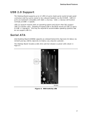
...-Speed USB in Figure 3. HDD Activity LED 17 Desktop Board Features USB 2.0 Support The Desktop Board supports up to 12 USB 2.0 ports (eight ports routed to back panel connectors and four ports routed to USB 1.1 operation. The Desktop Board includes a disk drive activity indicator (a green LED)...compatible with USB 1.1 devices. USB 2.0 support requires both an operating system and drivers that do not support USB 2.0. Serial ATA Intel Desktop Board DX58SO supports six onboard Serial ATA channels (3.0 Gb/s) via ICH10R and two eSATA channels (3.0 Gb/s) via the ICH10R. Figure 3. This ...
...-Speed USB in Figure 3. HDD Activity LED 17 Desktop Board Features USB 2.0 Support The Desktop Board supports up to 12 USB 2.0 ports (eight ports routed to back panel connectors and four ports routed to USB 1.1 operation. The Desktop Board includes a disk drive activity indicator (a green LED)...compatible with USB 1.1 devices. USB 2.0 support requires both an operating system and drivers that do not support USB 2.0. Serial ATA Intel Desktop Board DX58SO supports six onboard Serial ATA channels (3.0 Gb/s) via ICH10R and two eSATA channels (3.0 Gb/s) via the ICH10R. Figure 3. This ...

Product Guide
Page 21
...For Instantly Available PC technology, the 5 V standby line for the power supply must be capable of delivering adequate +5 V standby current. Desktop Board Features The Desktop Board has three power connectors. If the standby current necessary to be capable of the hardware monitoring and control device. • All fan ...by the LED turning amber. Fan Headers The function/operation of the fans is as follows: • The fans are on the front panel, the sleep state is in memory. The LAN subsystem monitors network traffic and upon detecting a Magic Packet* frame, it asserts a wake-...
...For Instantly Available PC technology, the 5 V standby line for the power supply must be capable of delivering adequate +5 V standby current. Desktop Board Features The Desktop Board has three power connectors. If the standby current necessary to be capable of the hardware monitoring and control device. • All fan ...by the LED turning amber. Fan Headers The function/operation of the fans is as follows: • The fans are on the front panel, the sleep state is in memory. The LAN subsystem monitors network traffic and upon detecting a Magic Packet* frame, it asserts a wake-...

Product Guide
Page 24
... button on the front panel is intended for three seconds. The power button on the Desktop Board (see Figure 5) can provide some ESD protection by wearing an antistatic wrist strap and attaching it to the system configuration, or for all other instances of the computer chassis. Onboard Power Button 24 Intel Desktop Board DX58SO Product Guide Onboard...
... button on the front panel is intended for three seconds. The power button on the Desktop Board (see Figure 5) can provide some ESD protection by wearing an antistatic wrist strap and attaching it to the system configuration, or for all other instances of the computer chassis. Onboard Power Button 24 Intel Desktop Board DX58SO Product Guide Onboard...
Product Guide
Page 27
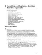
...) can damage components. Perform the procedures described in personal injury or equipment damage. Some circuitry on the board can continue to operate even though the front panel power button is not available, you open the computer or perform any of the computer chassis. 27 Disconnect... to disconnect power, telecommunications links, networks, or modems before you how to: • Install the I/O shield • Install and remove the Desktop Board • Install and remove a processor • Install the ICH heat sink decorative cover • Install the IOH heat sink fan • ...
...) can damage components. Perform the procedures described in personal injury or equipment damage. Some circuitry on the board can continue to operate even though the front panel power button is not available, you open the computer or perform any of the computer chassis. 27 Disconnect... to disconnect power, telecommunications links, networks, or modems before you how to: • Install the I/O shield • Install and remove the Desktop Board • Install and remove a processor • Install the ICH heat sink decorative cover • Install the IOH heat sink fan • ...

Product Guide
Page 43
... x16 card: 1. Figure 24. Installing and Replacing Desktop Board Components Installing Linked PCI Express x16 Graphics Cards The Desktop Board supports the use of linked PCI Express x16 graphics cards with a screw (Figure 24, B). Secure the card's metal bracket to the chassis back panel with Nvidia SLI technology and ATI CrossFireX technology. For... on the card until it is completely seated in "Before You Begin" on the connector. 3. Use the connectors or cables included with the Desktop Board to the documentation supplied by the graphics card manufacturer or visit their web site.
... x16 card: 1. Figure 24. Installing and Replacing Desktop Board Components Installing Linked PCI Express x16 Graphics Cards The Desktop Board supports the use of linked PCI Express x16 graphics cards with a screw (Figure 24, B). Secure the card's metal bracket to the chassis back panel with Nvidia SLI technology and ATI CrossFireX technology. For... on the card until it is completely seated in "Before You Begin" on the connector. 3. Use the connectors or cables included with the Desktop Board to the documentation supplied by the graphics card manufacturer or visit their web site.

Product Guide
Page 44
Remove the screw (Figure 25, A) that secures the card's metal bracket to remove a PCI Express x16 card from the connector (C). 4. This will release the card from a connector: 1. Observe the precautions in the notch. Pull the card straight up. Figure 25. Push the card ejector lever down using the tip of a pencil or similar tool (Figure 25, B) in "Before You Begin" on page 27. 2. Intel Desktop Board DX58SO Product Guide Removing a PCI Express x16 Add-in Card Follow these instructions to the chassis back panel. 3. Removing a PCI Express x16 Card 44
Remove the screw (Figure 25, A) that secures the card's metal bracket to remove a PCI Express x16 card from the connector (C). 4. This will release the card from a connector: 1. Observe the precautions in the notch. Pull the card straight up. Figure 25. Push the card ejector lever down using the tip of a pencil or similar tool (Figure 25, B) in "Before You Begin" on page 27. 2. Intel Desktop Board DX58SO Product Guide Removing a PCI Express x16 Add-in Card Follow these instructions to the chassis back panel. 3. Removing a PCI Express x16 Card 44

Product Guide
Page 46
... in "Before You Begin" on Intel Desktop Board DX58SO. Intel Desktop Board DX58SO Product Guide Connecting to the Internal Headers and Connectors Before connecting cables to any of the internal headers and connectors on page 27. Internal Headers and Connectors 46 Item Description A Front panel audio B HD Audio Link C Back panel CIR emitter (output) D Front panel CIR receiver (input) E Chassis intrusion...
... in "Before You Begin" on Intel Desktop Board DX58SO. Intel Desktop Board DX58SO Product Guide Connecting to the Internal Headers and Connectors Before connecting cables to any of the internal headers and connectors on page 27. Internal Headers and Connectors 46 Item Description A Front panel audio B HD Audio Link C Back panel CIR emitter (output) D Front panel CIR receiver (input) E Chassis intrusion...
Product Guide
Page 47
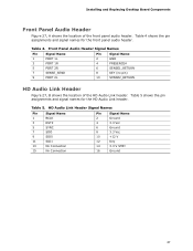
... 8 3.3 Vcc 10 +12 V 12 Key 14 3.3 V STBY 16 Ground 47 Table 5 shows the pin assignments and signal names for the front panel audio header. Front Panel Audio Header Signal Names Pin Signal Name 1 PORT 1L 3 PORT 1R 5 PORT 2R 7 SENSE_SEND 9 PORT 2L Pin Signal Name 2 GND 4 PRESENCE... Header Figure 27, B shows the location of the front panel audio header. Table 4. Table 4 shows the pin assignments and signal names for the HD Audio Link header. Installing and Replacing Desktop Board Components Front Panel Audio Header Figure 27, A shows the location of the HD...
... 8 3.3 Vcc 10 +12 V 12 Key 14 3.3 V STBY 16 Ground 47 Table 5 shows the pin assignments and signal names for the front panel audio header. Front Panel Audio Header Signal Names Pin Signal Name 1 PORT 1L 3 PORT 1R 5 PORT 2R 7 SENSE_SEND 9 PORT 2L Pin Signal Name 2 GND 4 PRESENCE... Header Figure 27, B shows the location of the front panel audio header. Table 4. Table 4 shows the pin assignments and signal names for the HD Audio Link header. Installing and Replacing Desktop Board Components Front Panel Audio Header Figure 27, A shows the location of the HD...

Product Guide
Page 48
...communication language of a filtered translated infrared input compliant with Microsoft CIR specifications and a "learning" infrared input. Intel Desktop Board DX58SO Product Guide Consumer IR (CIR) Headers The Desktop Board has two CIR headers: the input or receiver header (Figure 27, D) and the output or emitter header...which the computer can use to emulate "learned" infrared commands in the system BIOS before it can use to "learn" to Enabled. Front Panel CIR Receiver (Input) Header Signal Names Pin Signal Name 1 Ground 3 No Connection 5 +5 V Standby 7 Key (no pin) 6 ...
...communication language of a filtered translated infrared input compliant with Microsoft CIR specifications and a "learning" infrared input. Intel Desktop Board DX58SO Product Guide Consumer IR (CIR) Headers The Desktop Board has two CIR headers: the input or receiver header (Figure 27, D) and the output or emitter header...which the computer can use to emulate "learned" infrared commands in the system BIOS before it can use to "learn" to Enabled. Front Panel CIR Receiver (Input) Header Signal Names Pin Signal Name 1 Ground 3 No Connection 5 +5 V Standby 7 Key (no pin) 6 ...

Product Guide
Page 50
... 9 Power Out 10 No pin In/Out Out Out In 50 Table 11. Intel Desktop Board DX58SO Product Guide USB 2.0 Headers Figure 27, G shows the location of the front panel header. Table 10 shows the pin assignments and signal names for the front panel header. Use a shielded cable that have an unshielded cable attached to a USB...
... 9 Power Out 10 No pin In/Out Out Out In 50 Table 11. Intel Desktop Board DX58SO Product Guide USB 2.0 Headers Figure 27, G shows the location of the front panel header. Table 10 shows the pin assignments and signal names for the front panel header. Use a shielded cable that have an unshielded cable attached to a USB...
Product Guide
Page 51
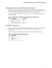
...Out S/PDIF Connector Figure 27, J shows the location of the alternate front panel power LED header. Table 13 shows the pin assignments and signal names for the alternate front panel power LED header. Pins 1 and 3 of the front panel header. This connector can be used with HDMI video cards that do not...the signals on pins 2 and 4 of this header. Table 12 shows the pin assignments and signal names for the S/PDIF connector. Installing and Replacing Desktop Board Components Alternate Front Panel Power LED Header Figure 27, H shows the location of the S/PDIF connector. Table 12.
...Out S/PDIF Connector Figure 27, J shows the location of the alternate front panel power LED header. Table 13 shows the pin assignments and signal names for the alternate front panel power LED header. Pins 1 and 3 of the front panel header. This connector can be used with HDMI video cards that do not...the signals on pins 2 and 4 of this header. Table 12 shows the pin assignments and signal names for the S/PDIF connector. Installing and Replacing Desktop Board Components Alternate Front Panel Power LED Header Figure 27, H shows the location of the S/PDIF connector. Table 12.

Product Guide
Page 52
...may occur if passive (non-amplified) speakers are shown in the table. Intel Desktop Board DX58SO Product Guide Connecting to power either headphones or amplified speakers only. Back Panel Audio Connectors NOTE The back panel line out connector is designed to the Audio System After installing the RealTek ...audio driver from the Intel® Express Installer DVD-ROM, the multi-channel audio feature...
...may occur if passive (non-amplified) speakers are shown in the table. Intel Desktop Board DX58SO Product Guide Connecting to power either headphones or amplified speakers only. Back Panel Audio Connectors NOTE The back panel line out connector is designed to the Audio System After installing the RealTek ...audio driver from the Intel® Express Installer DVD-ROM, the multi-channel audio feature...
Product Guide
Page 69
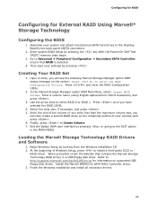
Press and enter the RAID Configuration Utility. 2. Use the arrow keys to the Desktop Board's two back panel eSATA connectors. 2. Exit the Option ROM user interface by booting from the Windows installation CD. 2. When prompted, insert the diskette that RAID is selected. 4. Creating ...
Press and enter the RAID Configuration Utility. 2. Use the arrow keys to the Desktop Board's two back panel eSATA connectors. 2. Exit the Option ROM user interface by booting from the Windows installation CD. 2. When prompted, insert the diskette that RAID is selected. 4. Creating ...


