Product Guide
Page 6
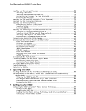
Intel Desktop Board DX58SO Product Guide Installing and Removing a Processor 31 Installing a Processor 31 Installing the Processor Fan Heat Sink 35 Connecting the Processor Fan Heat Sink Cable 35 ... Connecting the Serial ATA (SATA) Cables 45 Connecting to the Internal Headers and Connectors 46 Front Panel Audio Header 47 HD Audio Link Header 47 Consumer IR (CIR) Headers 48 Chassis Intrusion Header 49 IEEE 1394a Header 49 USB 2.0 Headers 50 Front Panel Header 50 Alternate Front Panel Power LED Header 51 S/PDIF Connector 51 Connecting to the Audio System 52 Connecting...
Intel Desktop Board DX58SO Product Guide Installing and Removing a Processor 31 Installing a Processor 31 Installing the Processor Fan Heat Sink 35 Connecting the Processor Fan Heat Sink Cable 35 ... Connecting the Serial ATA (SATA) Cables 45 Connecting to the Internal Headers and Connectors 46 Front Panel Audio Header 47 HD Audio Link Header 47 Consumer IR (CIR) Headers 48 Chassis Intrusion Header 49 IEEE 1394a Header 49 USB 2.0 Headers 50 Front Panel Header 50 Alternate Front Panel Power LED Header 51 S/PDIF Connector 51 Connecting to the Audio System 52 Connecting...
Product Guide
Page 8
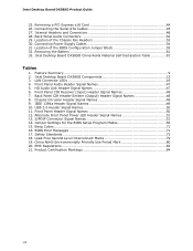
... BIOS Configuration Jumper Block 55 32. Connecting Power Supply Cables 54 31. Intel Desktop Board DX58SO Components 12 3. Front Panel CIR Receiver (Input) Header Signal Names 48 7. Removing a PCI Express x16 Card 44 26. Back Panel Audio Connectors 52 29. Front Panel Audio Header Signal Names 47 5. Intel Desktop Board DX58SO Product Guide 25. Lead-Free Second Level Interconnect Marks 79 19. Jumper...
... BIOS Configuration Jumper Block 55 32. Connecting Power Supply Cables 54 31. Intel Desktop Board DX58SO Components 12 3. Front Panel CIR Receiver (Input) Header Signal Names 48 7. Removing a PCI Express x16 Card 44 26. Back Panel Audio Connectors 52 29. Front Panel Audio Header Signal Names 47 5. Intel Desktop Board DX58SO Product Guide 25. Lead-Free Second Level Interconnect Marks 79 19. Jumper...
Product Guide
Page 9
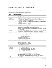
...Intel® Desktop Board DX58SO. Table 1. 1 Desktop Board Features This chapter briefly describes the features of the Desktop Board. Feature Summary Form Factor Processor Main Memory Chipset Graphics Audio Expansion Capabilities Legacy I/O Support Peripheral Interfaces RAID ATX (304.80 millimeters [12.00 inches] x 243.84 millimeters [9.60 inches]) Support for an Intel...channel audio subsystem, featuring: ― Intel® High Definition Audio interface ― RealTek* ALC889 codec • HD Audio Link header • HD Audio front panel header • Onboard 3-pin S/PDIF ...
...Intel® Desktop Board DX58SO. Table 1. 1 Desktop Board Features This chapter briefly describes the features of the Desktop Board. Feature Summary Form Factor Processor Main Memory Chipset Graphics Audio Expansion Capabilities Legacy I/O Support Peripheral Interfaces RAID ATX (304.80 millimeters [12.00 inches] x 243.84 millimeters [9.60 inches]) Support for an Intel...channel audio subsystem, featuring: ― Intel® High Definition Audio interface ― RealTek* ALC889 codec • HD Audio Link header • HD Audio front panel header • Onboard 3-pin S/PDIF ...

Product Guide
Page 15
...channel (7.1) audio (using the back panel audio connectors) and 2-channel audio (using the Intel High Definition Audio front panel header) Related Links: Go to the processor and the PCI Express bus. Desktop Board Features Intel® X58 Express Chipset The Intel X58 Express Chipset consists of the ...utilities http://support.intel.com/support/motherboards/desktop/ • The location of the onboard audio headers, Figure 27 on page 46 • The signal names for the Intel High Definition Audio front panel header and the HD Audio Link header, page 47 • The back panel audio connectors,...
...channel (7.1) audio (using the back panel audio connectors) and 2-channel audio (using the Intel High Definition Audio front panel header) Related Links: Go to the processor and the PCI Express bus. Desktop Board Features Intel® X58 Express Chipset The Intel X58 Express Chipset consists of the ...utilities http://support.intel.com/support/motherboards/desktop/ • The location of the onboard audio headers, Figure 27 on page 46 • The signal names for the Intel High Definition Audio front panel header and the HD Audio Link header, page 47 • The back panel audio connectors,...
Product Guide
Page 17
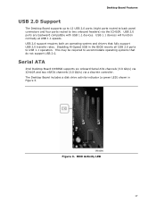
Serial ATA Intel Desktop Board DX58SO supports six onboard Serial ATA channels (3.0 Gb/s) via ICH10R and two eSATA channels (3.0 Gb/s) via the ICH10R. USB 2.0 support requires both an operating system and drivers that do not support USB 2.0. The Desktop Board includes a disk drive activity indicator...transfer rates. Disabling Hi-Speed USB in Figure 3. Desktop Board Features USB 2.0 Support The Desktop Board supports up to 12 USB 2.0 ports (eight ports routed to back panel connectors and four ports routed to two onboard headers) via a discrete controller. Figure 3. HDD Activity ...
Serial ATA Intel Desktop Board DX58SO supports six onboard Serial ATA channels (3.0 Gb/s) via ICH10R and two eSATA channels (3.0 Gb/s) via the ICH10R. USB 2.0 support requires both an operating system and drivers that do not support USB 2.0. The Desktop Board includes a disk drive activity indicator...transfer rates. Disabling Hi-Speed USB in Figure 3. Desktop Board Features USB 2.0 Support The Desktop Board supports up to 12 USB 2.0 ports (eight ports routed to back panel connectors and four ports routed to two onboard headers) via a discrete controller. Figure 3. HDD Activity ...

Product Guide
Page 21
...the computer is in memory. Desktop Board Features The Desktop Board has three power connectors. The Desktop Board has a 4-pin processor fan header, one 4-pin and two 3-pin chassis fan headers, and one 3-pin IOH fan header. Failure to support the ...standard Instantly Available (ACPI S3 sleep state) configuration. Failure to provide adequate standby current when using this feature can adjust the fan speed or switch the fan on the front panel...
...the computer is in memory. Desktop Board Features The Desktop Board has three power connectors. The Desktop Board has a 4-pin processor fan header, one 4-pin and two 3-pin chassis fan headers, and one 3-pin IOH fan header. Failure to support the ...standard Instantly Available (ACPI S3 sleep state) configuration. Failure to provide adequate standby current when using this feature can adjust the fan speed or switch the fan on the front panel...
Product Guide
Page 27
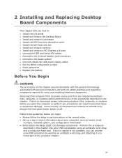
...by wearing an antistatic wrist strap and attaching it to operate even though the front panel power button is not available, you how to: • Install the I/O shield • Install and remove the Desktop Board • Install and remove a processor • Install the ICH heat sink ...decorative cover • Install the IOH heat sink fan • Install and remove memory • Install and remove a PCI Express x16 card • Connect the IDE and Serial ATA cables • Connect to the internal headers...
...by wearing an antistatic wrist strap and attaching it to operate even though the front panel power button is not available, you how to: • Install the I/O shield • Install and remove the Desktop Board • Install and remove a processor • Install the ICH heat sink ...decorative cover • Install the IOH heat sink fan • Install and remove memory • Install and remove a PCI Express x16 card • Connect the IDE and Serial ATA cables • Connect to the internal headers...

Product Guide
Page 46
... in "Before You Begin" on Intel Desktop Board DX58SO. Item Description A Front panel audio B HD Audio Link C Back panel CIR emitter (output) D Front panel CIR receiver (input) E Chassis intrusion Item Description F IEEE 1394a G USB 2.0 (2) H Alternate front panel power LED I Front panel J S/PDIF Figure 27. Internal Headers and Connectors 46 Intel Desktop Board DX58SO Product Guide Connecting to the Internal Headers and Connectors Before connecting cables...
... in "Before You Begin" on Intel Desktop Board DX58SO. Item Description A Front panel audio B HD Audio Link C Back panel CIR emitter (output) D Front panel CIR receiver (input) E Chassis intrusion Item Description F IEEE 1394a G USB 2.0 (2) H Alternate front panel power LED I Front panel J S/PDIF Figure 27. Internal Headers and Connectors 46 Intel Desktop Board DX58SO Product Guide Connecting to the Internal Headers and Connectors Before connecting cables...
Product Guide
Page 47
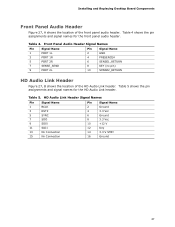
...Signal Name 2 GND 4 PRESENCE# 6 SENSE1_RETURN 8 KEY (no pin) 10 SENSE2_RETURN HD Audio Link Header Figure 27, B shows the location of the front panel audio header. Table 5 shows the pin assignments and signal names for the front panel audio header. Table 4 shows the pin assignments and signal names for the HD Audio Link...Connection Pin Signal Name 2 Ground 4 3.3 Vcc 6 Ground 8 3.3 Vcc 10 +12 V 12 Key 14 3.3 V STBY 16 Ground 47 Table 5. Installing and Replacing Desktop Board Components Front Panel Audio Header Figure 27, A shows the location of the HD Audio Link...
...Signal Name 2 GND 4 PRESENCE# 6 SENSE1_RETURN 8 KEY (no pin) 10 SENSE2_RETURN HD Audio Link Header Figure 27, B shows the location of the front panel audio header. Table 5 shows the pin assignments and signal names for the front panel audio header. Table 4 shows the pin assignments and signal names for the HD Audio Link...Connection Pin Signal Name 2 Ground 4 3.3 Vcc 6 Ground 8 3.3 Vcc 10 +12 V 12 Key 14 3.3 V STBY 16 Ground 47 Table 5. Installing and Replacing Desktop Board Components Front Panel Audio Header Figure 27, A shows the location of the HD Audio Link...

Product Guide
Page 48
... user remotes. Back Panel CIR Header Emitter (Output) Header Signal Names Pin Signal Name 1 Emitter Out 1 3 Ground 5 Jack Detect 1 Pin Signal Name 2 Emitter Out 2 4 Key (no pin) Pin Signal Name 2 LED 4 Learn-In 6 Vcc 8 CIR Input Table 7. Intel Desktop Board DX58SO Product Guide Consumer IR (CIR) Headers The Desktop Board has two CIR headers: the input or receiver header (Figure 27, D) and...
... user remotes. Back Panel CIR Header Emitter (Output) Header Signal Names Pin Signal Name 1 Emitter Out 1 3 Ground 5 Jack Detect 1 Pin Signal Name 2 Emitter Out 2 4 Key (no pin) Pin Signal Name 2 LED 4 Learn-In 6 Vcc 8 CIR Input Table 7. Intel Desktop Board DX58SO Product Guide Consumer IR (CIR) Headers The Desktop Board has two CIR headers: the input or receiver header (Figure 27, D) and...

Product Guide
Page 50
... the pin assignments and signal names for each USB 2.0 header. Table 11. Intel Desktop Board DX58SO Product Guide USB 2.0 Headers Figure 27, G shows the location of the front panel header. Table 10 shows the pin assignments and signal names for the front panel header. Table 10. Use a shielded cable that have an ...might not meet FCC Class B requirements, even if no device or a low-speed USB device is attached to the cable. Front Panel Header Signal Names Pin Description In/Out Pin Description Hard Drive Activity LED Power LED 1 Hard disk LED pull-up to connect two USB...
... the pin assignments and signal names for each USB 2.0 header. Table 11. Intel Desktop Board DX58SO Product Guide USB 2.0 Headers Figure 27, G shows the location of the front panel header. Table 10 shows the pin assignments and signal names for the front panel header. Table 10. Use a shielded cable that have an ...might not meet FCC Class B requirements, even if no device or a low-speed USB device is attached to the cable. Front Panel Header Signal Names Pin Description In/Out Pin Description Hard Drive Activity LED Power LED 1 Hard disk LED pull-up to connect two USB...
Product Guide
Page 51
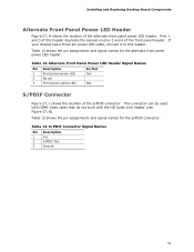
...chassis has a three-pin power LED cable, connect it to this header duplicate the signals on pins 2 and 4 of this header. Alternate Front Panel Power LED Header Signal Names Pin Description 1 Front panel green LED 2 No pin 3 Front panel yellow LED In/Out Out Out S/PDIF Connector Figure 27, J... 3 Ground 51 This connector can be used with HDMI video cards that do not work with the HD Audio Link header (see Figure 27, B). Installing and Replacing Desktop Board Components Alternate Front Panel Power LED Header Figure 27, H shows the location of the S/PDIF connector. Table 13.
...chassis has a three-pin power LED cable, connect it to this header duplicate the signals on pins 2 and 4 of this header. Alternate Front Panel Power LED Header Signal Names Pin Description 1 Front panel green LED 2 No pin 3 Front panel yellow LED In/Out Out Out S/PDIF Connector Figure 27, J... 3 Ground 51 This connector can be used with HDMI video cards that do not work with the HD Audio Link header (see Figure 27, B). Installing and Replacing Desktop Board Components Alternate Front Panel Power LED Header Figure 27, H shows the location of the S/PDIF connector. Table 13.


