
Product Specification
Page 5
Contents 1 Product Description 1.1 Overview 9 1.1.1 Feature Summary 9 1.1.2 Board Layout 11 1.1.3 Block Diagram 13 1.2 Legacy Considerations 14 1.3 Online Support 14 1.4 Processor 14 1.5 Intel® Q57 Express Chipset 15 1.6 System Memory 15 1.6.1 Memory Configurations 16 1.7 Graphics Subsystem 18 1.7.1 Integrated Graphics 18 1.7.2 PCI Express x16 Graphics 19 1.8 USB 19 1.9 SATA Interfaces 20 1.10 Legacy I/O Controller 21 1.10.1 Serial...
Contents 1 Product Description 1.1 Overview 9 1.1.1 Feature Summary 9 1.1.2 Board Layout 11 1.1.3 Block Diagram 13 1.2 Legacy Considerations 14 1.3 Online Support 14 1.4 Processor 14 1.5 Intel® Q57 Express Chipset 15 1.6 System Memory 15 1.6.1 Memory Configurations 16 1.7 Graphics Subsystem 18 1.7.1 Integrated Graphics 18 1.7.2 PCI Express x16 Graphics 19 1.8 USB 19 1.9 SATA Interfaces 20 1.10 Legacy I/O Controller 21 1.10.1 Serial...

Product Specification
Page 7
...Connectors and Headers 47 12. Location of the Intel ME "M" State LED 31 8. Power States and Targeted System Power 35 8. System Memory Map 45 10. Front Panel Audio Header for AC '97 Audio 50 16. Front Panel Audio Header for Intel HD Audio 49 15. SATA Connectors 50 ... States 24 5. Chassis Intrusion Header 50 19. Intel Remote PC Assist Technology Header 51 22. States for Front Panel Header 53 13. Alternate Front Panel Power LED Header 54 vii Back Panel Audio Connector Options 22 5. Supported Memory Configurations 15 4. Serial Port Header 49 12. Front...
...Connectors and Headers 47 12. Location of the Intel ME "M" State LED 31 8. Power States and Targeted System Power 35 8. System Memory Map 45 10. Front Panel Audio Header for AC '97 Audio 50 16. Front Panel Audio Header for Intel HD Audio 49 15. SATA Connectors 50 ... States 24 5. Chassis Intrusion Header 50 19. Intel Remote PC Assist Technology Header 51 22. States for Front Panel Header 53 13. Alternate Front Panel Power LED Header 54 vii Back Panel Audio Connector Options 22 5. Supported Memory Configurations 15 4. Serial Port Header 49 12. Front...
Product Specification
Page 9
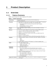
1 Product Description 1.1 Overview 1.1.1 Feature Summary Table 1 summarizes the major features of system memory with four DIMMs using 2 Gb memory technology • Support for non-ECC memory • Support for unbuffered ECC memory with Intel Xeon processor 3400 series • Integrated graphics support for processors with Intel® Graphics Technology: ― DVI-I ― DVI-D ― DisplayPort* • Discrete...
1 Product Description 1.1 Overview 1.1.1 Feature Summary Table 1 summarizes the major features of system memory with four DIMMs using 2 Gb memory technology • Support for non-ECC memory • Support for unbuffered ECC memory with Intel Xeon processor 3400 series • Integrated graphics support for processors with Intel® Graphics Technology: ― DVI-I ― DVI-D ― DisplayPort* • Discrete...

Product Specification
Page 14
... processors Chipset information BIOS and driver updates Tested memory Integration information Visit this board. 14 Use of supported processors. Intel Desktop Board DQ57TM Desktop Board Support Available configurations for providing power to support the Intel Core i7, Intel Core i5, Intel Core i3, Intel Pentium processors, and Intel Xeon processor 3400 series in the future. This board is...
... processors Chipset information BIOS and driver updates Tested memory Integration information Visit this board. 14 Use of supported processors. Intel Desktop Board DQ57TM Desktop Board Support Available configurations for providing power to support the Intel Core i7, Intel Core i5, Intel Core i3, Intel Pentium processors, and Intel Xeon processor 3400 series in the future. This board is...
Product Specification
Page 15
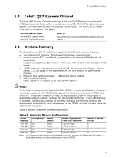
... the SPD data and program the chipset to Section 2.1.1 on page 43 for unbuffered ECC memory when used with an Intel Xeon processor 3400 series • 16 GB maximum total system memory (with DIMMs that support the Serial Presence Detect (SPD) data structure. Table 3 lists ... The PCH is installed, the BIOS will attempt to http://www.intel.com/products/desktop/chipsets/index.htm Chapter 2 1.6 System Memory The board has four DIMM sockets and supports the following memory features: • Two independent memory channels with interleaved mode support • Support for non-ECC,...
... the SPD data and program the chipset to Section 2.1.1 on page 43 for unbuffered ECC memory when used with an Intel Xeon processor 3400 series • 16 GB maximum total system memory (with DIMMs that support the Serial Presence Detect (SPD) data structure. Table 3 lists ... The PCH is installed, the BIOS will attempt to http://www.intel.com/products/desktop/chipsets/index.htm Chapter 2 1.6 System Memory The board has four DIMM sockets and supports the following memory features: • Two independent memory channels with interleaved mode support • Support for non-ECC,...
Product Specification
Page 16
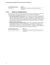
...• Single channel (Asymmetric) mode. This mode is installed or the memory capacities are equal. This mode offers the highest throughput for real world applications. Intel Desktop Board DQ57TM Technical Product Specification For information about ... If different speed DIMMs are used ...between channels, the slowest memory timing will be equal. Tested Memory Refer to single channel bandwidth operation for...
...• Single channel (Asymmetric) mode. This mode is installed or the memory capacities are equal. This mode offers the highest throughput for real world applications. Intel Desktop Board DQ57TM Technical Product Specification For information about ... If different speed DIMMs are used ...between channels, the slowest memory timing will be equal. Tested Memory Refer to single channel bandwidth operation for...

Product Specification
Page 17
Memory Channel and DIMM Configuration NOTE When using a processor without Intel Graphics Technology, there must always be memory installed into any or both of the DIMM 0 (blue) memory sockets for the system to boot. 17 Product Description Figure 3 illustrates the memory channel and DIMM configuration. Figure 3.
Memory Channel and DIMM Configuration NOTE When using a processor without Intel Graphics Technology, there must always be memory installed into any or both of the DIMM 0 (blue) memory sockets for the system to boot. 17 Product Description Figure 3 illustrates the memory channel and DIMM configuration. Figure 3.

Product Specification
Page 25
Product Description 1.13 Real-Time Clock Subsystem A coin-cell battery (CR2032) powers the real-time clock and CMOS memory. Figure 1 on page 11 shows the location of the battery. When the computer is accurate to ± 13 minutes/year at 25 ºC with an ...
Product Description 1.13 Real-Time Clock Subsystem A coin-cell battery (CR2032) powers the real-time clock and CMOS memory. Figure 1 on page 11 shows the location of the battery. When the computer is accurate to ± 13 minutes/year at 25 ºC with an ...

Product Specification
Page 27
Product Description 1.15 Platform Management and Security In addition to Intel AMT the Intel DQ57TM Desktop Board integrates several hardware management features, including the following: • Fan monitoring and control • Thermal and voltage monitoring • Chassis ...processor and PCH, as well as needed 1.15.1.2 Fan Monitoring Fan monitoring can adjust fan speed as near the CPU voltage regulators and system memory • Monitoring of an external microcontroller. 1.15.1 Hardware Management Subsystem The hardware management features enable the board to detect levels above or ...
Product Description 1.15 Platform Management and Security In addition to Intel AMT the Intel DQ57TM Desktop Board integrates several hardware management features, including the following: • Fan monitoring and control • Thermal and voltage monitoring • Chassis ...processor and PCH, as well as needed 1.15.1.2 Fan Monitoring Fan monitoring can adjust fan speed as near the CPU voltage regulators and system memory • Monitoring of an external microcontroller. 1.15.1 Hardware Management Subsystem The hardware management features enable the board to detect levels above or ...

Product Specification
Page 43
.... 43 Figure 9 shows a schematic of addressable system memory. 2 Technical Reference 2.1 Memory Resources 2.1.1 Addressable Memory The board utilizes 16 GB of the system memory map. On a system that has 16 GB of system memory installed, it is allocated for other system critical functions.... Typically the address space that is no overlap of the installed memory due to reclaim the physical memory overlapped by the memory mapped I/O logical address space. These functions include the following: • BIOS/SPI Flash device (64 ...
.... 43 Figure 9 shows a schematic of addressable system memory. 2 Technical Reference 2.1 Memory Resources 2.1.1 Addressable Memory The board utilizes 16 GB of the system memory map. On a system that has 16 GB of system memory installed, it is allocated for other system critical functions.... Typically the address space that is no overlap of the installed memory due to reclaim the physical memory overlapped by the memory mapped I/O logical address space. These functions include the following: • BIOS/SPI Flash device (64 ...

Product Specification
Page 45
... 100000 - 3FFFFFFFF 960 K - 1024 K F0000 - Dependent on video adapter used. A fault in the load presented by memory manager software) Extended conventional memory Conventional memory 2.2 Connectors and Headers CAUTION Only the following connectors and headers have overcurrent protection: back panel and front panel USB. DFFFF 640 ...overcurrent protection and cause damage to devices inside the computer's chassis, such as fans and internal peripherals. Video memory and BIOS Extended BIOS data (movable by the external devices could cause damage to the PCI Conventional bus)....
... 100000 - 3FFFFFFFF 960 K - 1024 K F0000 - Dependent on video adapter used. A fault in the load presented by memory manager software) Extended conventional memory Conventional memory 2.2 Connectors and Headers CAUTION Only the following connectors and headers have overcurrent protection: back panel and front panel USB. DFFFF 640 ...overcurrent protection and cause damage to devices inside the computer's chassis, such as fans and internal peripherals. Video memory and BIOS Extended BIOS data (movable by the external devices could cause damage to the PCI Conventional bus)....

Product Specification
Page 65
The BIOS Setup program can be used to put the board in configure mode. Maintenance Main Configuration Performance Security Power Boot Intel ME Exit NOTE The maintenance menu is displayed only when the board is in configure mode. 65 The initial production BIOSs are identified ...as TMIBX10H.86A. 3 Overview of BIOS Features 3.1 Introduction The board uses an Intel BIOS that is stored in a 64 Mbit (8,192 KB) Serial Peripheral Interface Flash Memory (SPI Flash) device which can be updated using a set of utilities. The SPI Flash contains the BIOS ...
The BIOS Setup program can be used to put the board in configure mode. Maintenance Main Configuration Performance Security Power Boot Intel ME Exit NOTE The maintenance menu is displayed only when the board is in configure mode. 65 The initial production BIOSs are identified ...as TMIBX10H.86A. 3 Overview of BIOS Features 3.1 Introduction The board uses an Intel BIOS that is stored in a 64 Mbit (8,192 KB) Serial Peripheral Interface Flash Memory (SPI Flash) device which can be updated using a set of utilities. The SPI Flash contains the BIOS ...

Product Specification
Page 66
... field (i.e., date/time) Executes command or selects the submenu Load the default configuration values for menu screens. Intel Desktop Board DQ57TM Technical Product Specification Table 33 lists the BIOS Setup program menu features. BIOS Setup Program Menu Bar Maintenance Main... processor and memory configuration Configures advanced features available through the chipset Configures Memory and Processor overrides Sets passwords and security features Power Boot Configures power management features Selects boot options Intel ME Exit Configure Intel ME and Intel AMT settings ...
... field (i.e., date/time) Executes command or selects the submenu Load the default configuration values for menu screens. Intel Desktop Board DQ57TM Technical Product Specification Table 33 lists the BIOS Setup program menu features. BIOS Setup Program Menu Bar Maintenance Main... processor and memory configuration Configures advanced features available through the chipset Configures Memory and Processor overrides Sets passwords and security features Power Boot Configures power management features Selects boot options Intel ME Exit Configure Intel ME and Intel AMT settings ...

Product Specification
Page 67
...; BIOS data, such as the BIOS revision level • Fixed-system data, such as peripherals, serial numbers, and asset tags • Resource data, such as memory size, cache size, and processor speed • Dynamic data, such as follows: 1. Legacy USB support operates as event detection and error logging Non-Plug and...
...; BIOS data, such as the BIOS revision level • Fixed-system data, such as peripherals, serial numbers, and asset tags • Resource data, such as memory size, cache size, and processor speed • Dynamic data, such as follows: 1. Legacy USB support operates as event detection and error logging Non-Plug and...

Product Specification
Page 68
... a file on a hard disk, a USB drive (a flash drive or a USB drive), or an optical drive. • Intel® Flash Memory Update Utility, which enables automated updating while in US English. 68 Both utilities verify that location/device. For information about BIOS update utilities... Language Support The BIOS Setup program and help messages are available on the Intel World Wide Web site: • Intel® Express BIOS Update utility, which requires booting from DOS. Intel Desktop Board DQ57TM Technical Product Specification 3.4 BIOS Updates The BIOS can be updated using either ...
... a file on a hard disk, a USB drive (a flash drive or a USB drive), or an optical drive. • Intel® Flash Memory Update Utility, which enables automated updating while in US English. 68 Both utilities verify that location/device. For information about BIOS update utilities... Language Support The BIOS Setup program and help messages are available on the Intel World Wide Web site: • Intel® Express BIOS Update utility, which requires booting from DOS. Intel Desktop Board DQ57TM Technical Product Specification 3.4 BIOS Updates The BIOS can be updated using either ...

Product Specification
Page 75
... Type Pattern F2 Setup/F10 Boot Menu One 0.5 second beep when BIOS is powered off (1.0 second each ) for eight beeps, followed by system shut down. Memory error On-off . Frequency/Comments 932 Hz 932 Hz For processors requiring an add-in graphics card installed) On-off (1.0 second each) two times, then...
... Type Pattern F2 Setup/F10 Boot Menu One 0.5 second beep when BIOS is powered off (1.0 second each ) for eight beeps, followed by system shut down. Memory error On-off . Frequency/Comments 932 Hz 932 Hz For processors requiring an add-in graphics card installed) On-off (1.0 second each) two times, then...
Product Specification
Page 76
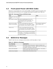
... Low The battery may have been corrupted. Replace the battery soon. CMOS Checksum Bad The CMOS checksum is complete. Memory Size Decreased Memory size has decreased since the last boot. No Boot Device Available System did not find a device to reset values. Table... 40. CMOS memory may be bad. Video error (no memory was removed, then memory may be losing power. If no add-in graphics card 4.4 BIOS Error Messages Table 41 lists the error messages and provides a brief description of 16 blinks. Intel Desktop Board DQ57TM Technical Product Specification ...
... Low The battery may have been corrupted. Replace the battery soon. CMOS Checksum Bad The CMOS checksum is complete. Memory Size Decreased Memory size has decreased since the last boot. No Boot Device Available System did not find a device to reset values. Table... 40. CMOS memory may be bad. Video error (no memory was removed, then memory may be losing power. If no add-in graphics card 4.4 BIOS Error Messages Table 41 lists the error messages and provides a brief description of 16 blinks. Intel Desktop Board DQ57TM Technical Product Specification ...

Product Specification
Page 77
... POST codes generated by any PEIM/driver for debug. 10 - 1F Host Processors: 1F is an unrecoverable CPU error. 20 - 2F Memory/Chipset: 2F is no memory detected or no useful memory detected. 30 - 3F Recovery: 3F indicated recovery failure. 40 - 4F Reserved for future use (new output console codes). 90 - 9F Input...
... POST codes generated by any PEIM/driver for debug. 10 - 1F Host Processors: 1F is an unrecoverable CPU error. 20 - 2F Memory/Chipset: 2F is no memory detected or no useful memory detected. 30 - 3F Recovery: 3F indicated recovery failure. 40 - 4F Reserved for future use (new output console codes). 90 - 9F Input...

Product Specification
Page 78
Intel Desktop Board DQ57TM Technical Product Specification Table 43. Port 80h POST Codes POST Code Description of POST Operation Host Processor 10 Power-on initialization of the host processor (Boot Strap Processor) 11 Host processor cache initialization (including APs) 12 Starting Application processor initialization 13 SMM initialization Chipset 21 Initializing a chipset component Memory 22...
Intel Desktop Board DQ57TM Technical Product Specification Table 43. Port 80h POST Codes POST Code Description of POST Operation Host Processor 10 Power-on initialization of the host processor (Boot Strap Processor) 11 Host processor cache initialization (including APs) 12 Starting Application processor initialization 13 SMM initialization Chipset 21 Initializing a chipset component Memory 22...

Product Specification
Page 79
... media BDS Dy Trying boot selection y (y=0 to 15) PEI Core E0 Started dispatching PEIMs (emitted on first report of EFI_SW_PC_INIT_BEGIN EFI_SW_PEI_PC_HANDOFF_TO_NEXT) E2 E1, E3 Permanent memory found Reserved for PEI/PEIMs DXE Core E4 Entered DXE phase E5 Started dispatching drivers E6 Started connecting drivers continued 79
... media BDS Dy Trying boot selection y (y=0 to 15) PEI Core E0 Started dispatching PEIMs (emitted on first report of EFI_SW_PC_INIT_BEGIN EFI_SW_PEI_PC_HANDOFF_TO_NEXT) E2 E1, E3 Permanent memory found Reserved for PEI/PEIMs DXE Core E4 Entered DXE phase E5 Started dispatching drivers E6 Started connecting drivers continued 79


