Product Guide
Page 3
... use in personal computers (PC) for general audiences. It is intended for Intel Rapid Recover Technology A Error Messages and Indicators: information about BIOS error messages and beep codes B Regulatory Compliance: safety and EMC regulations and product certifications Conventions The following conventions are arranged as follows: 1 Desktop Board Features: a summary of product features 2 Installing and Replacing Desktop Board Components: instructions on how to update the BIOS 4 Configuring for RAID (Intel®...
... use in personal computers (PC) for general audiences. It is intended for Intel Rapid Recover Technology A Error Messages and Indicators: information about BIOS error messages and beep codes B Regulatory Compliance: safety and EMC regulations and product certifications Conventions The following conventions are arranged as follows: 1 Desktop Board Features: a summary of product features 2 Installing and Replacing Desktop Board Components: instructions on how to update the BIOS 4 Configuring for RAID (Intel®...
Product Guide
Page 6
... for Intel® High Definition Audio 51 Connecting to the Serial Port Header 52 Connecting to the Chassis Intrusion Header 52 Connecting to the Alternate Front Panel Power LED Header 53 Connecting to the Front Panel Header 53 Connecting to the USB 2.0 Headers 54 Connecting to the Audio System 54 Connecting Chassis Fan and Power Supply Cables 55 Connecting Chassis Fan Cables 55 Connecting Supply Power Cables 56 Setting the BIOS Configuration Jumper 57 Clearing or Changing Passwords 58 Clearing BIOS Security Passwords 58 Clearing or Changing Hard Disk Drive Passwords 59 Replacing...
... for Intel® High Definition Audio 51 Connecting to the Serial Port Header 52 Connecting to the Chassis Intrusion Header 52 Connecting to the Alternate Front Panel Power LED Header 53 Connecting to the Front Panel Header 53 Connecting to the USB 2.0 Headers 54 Connecting to the Audio System 54 Connecting Chassis Fan and Power Supply Cables 55 Connecting Chassis Fan Cables 55 Connecting Supply Power Cables 56 Setting the BIOS Configuration Jumper 57 Clearing or Changing Passwords 58 Clearing BIOS Security Passwords 58 Clearing or Changing Hard Disk Drive Passwords 59 Replacing...
Product Guide
Page 7
... Removing a PCI Express x16 Card 46 vii Desktop Board DQ35JO Mounting Screw Hole Locations 34 7. Lift the Socket Lever 35 8. Dual Channel Memory Configuration with Two DIMMs 40 15. Lift the Load Plate 36 9. Connecting the Processor Fan Heat Sink Cable to the Processor Fan Header ..........39 14. Installing a DIMM 43 19. Installing the I/O Shield 33 6. Contents 4 Configuring for RAID (Intel® Matrix Storage Technology) Configuring the BIOS for Intel Matrix Storage Technology 69 Creating Your RAID Set 69 Loading the Intel Matrix Storage Technology RAID Drivers...
... Removing a PCI Express x16 Card 46 vii Desktop Board DQ35JO Mounting Screw Hole Locations 34 7. Lift the Socket Lever 35 8. Dual Channel Memory Configuration with Two DIMMs 40 15. Lift the Load Plate 36 9. Connecting the Processor Fan Heat Sink Cable to the Processor Fan Header ..........39 14. Installing a DIMM 43 19. Installing the I/O Shield 33 6. Contents 4 Configuring for RAID (Intel® Matrix Storage Technology) Configuring the BIOS for Intel Matrix Storage Technology 69 Creating Your RAID Set 69 Loading the Intel Matrix Storage Technology RAID Drivers...

Product Guide
Page 8
... BIOS Configuration Jumper Block 57 29. Intel AMT Status Indicator 20 6. IEEE 1394a Signal Header Names 51 8. Jumper Settings for the BIOS Setup Program Modes 58 15. Lead-Free Board Markings 82 19. Product Certification Markings 85 viii Intel Desktop Board DQ35JO Product Guide 21. LAN Connector LEDs 19 5. Front Panel Header 53 13. Connecting the IDE Cable 47 22. Desktop Board DQ35JO Components 13 3. Serial Port Header Signal Names 52 10. Chassis Intrusion Header 52 11. EMC Regulations 83 20. Location of the Chassis Fan Headers...
... BIOS Configuration Jumper Block 57 29. Intel AMT Status Indicator 20 6. IEEE 1394a Signal Header Names 51 8. Jumper Settings for the BIOS Setup Program Modes 58 15. Lead-Free Board Markings 82 19. Product Certification Markings 85 viii Intel Desktop Board DQ35JO Product Guide 21. LAN Connector LEDs 19 5. Front Panel Header 53 13. Connecting the IDE Cable 47 22. Desktop Board DQ35JO Components 13 3. Serial Port Header Signal Names 52 10. Chassis Intrusion Header 52 11. EMC Regulations 83 20. Location of the Chassis Fan Headers...
Product Guide
Page 9
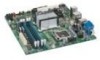
... graphics controller • One PCI Express* x16 connector supporting PCI Express graphics cards • 4-channel (2 + 2) onboard audio subsystem featuring: ― Intel® High Definition Audio interface ― RealTek* ALC268-GR audio codec • HD Audio Link header Intel® 82566DM Gigabit (10/100/1000 Mb/s) Ethernet LAN controller • One PCI Express x16 connector • Two PCI Express x1 connectors • One PCI* connector Legacy I/O Controller that provides one serial port via an onboard header • Up to 12 USB 2.0 ports ― Six ports routed to the back panel...
... graphics controller • One PCI Express* x16 connector supporting PCI Express graphics cards • 4-channel (2 + 2) onboard audio subsystem featuring: ― Intel® High Definition Audio interface ― RealTek* ALC268-GR audio codec • HD Audio Link header Intel® 82566DM Gigabit (10/100/1000 Mb/s) Ethernet LAN controller • One PCI Express x16 connector • Two PCI Express x1 connectors • One PCI* connector Legacy I/O Controller that provides one serial port via an onboard header • Up to 12 USB 2.0 ports ― Six ports routed to the back panel...
Product Guide
Page 10
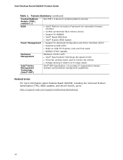
Intel Desktop Board DQ35JO Product Guide Table 1. Feature Summary (continued) Trusted Platform Module (TPM), revision 1.2 BIOS One TPM 1.2 device to enhance platform security • Intel® Platform Innovation Framework for extensible firmware interface • 32 Mbit symmetrical flash memory device • Support for SMBIOS • Intel® Rapid BIOS Boot • Intel® Express BIOS Update Power Management • Support for Advanced Configuration and Power Interface (ACPI) • Suspend to RAM (STR) • Wake on USB, PCI Express, LAN, and front panel •...
Intel Desktop Board DQ35JO Product Guide Table 1. Feature Summary (continued) Trusted Platform Module (TPM), revision 1.2 BIOS One TPM 1.2 device to enhance platform security • Intel® Platform Innovation Framework for extensible firmware interface • 32 Mbit symmetrical flash memory device • Support for SMBIOS • Intel® Rapid BIOS Boot • Intel® Express BIOS Update Power Management • Support for Advanced Configuration and Power Interface (ACPI) • Suspend to RAM (STR) • Wake on USB, PCI Express, LAN, and front panel •...
Product Guide
Page 17
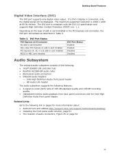
... utilities http://support.intel.com/support/motherboards/desktop/ • Installing the front panel audio solution, page 51 • The location of the following: • Intel® ICH9DO I display is connected, only the digital signal will behave as described in card installed ADD2 or MEC card installed DVI Port Status Enabled Enabled Disabled Disabled Audio Subsystem The onboard audio subsystem consists of audio connectors, Figure 25 on page 54 17 The maximum supported resolution is compliant with the DVI 1.0 specification...
... utilities http://support.intel.com/support/motherboards/desktop/ • Installing the front panel audio solution, page 51 • The location of the following: • Intel® ICH9DO I display is connected, only the digital signal will behave as described in card installed ADD2 or MEC card installed DVI Port Status Enabled Enabled Disabled Disabled Audio Subsystem The onboard audio subsystem consists of audio connectors, Figure 25 on page 54 17 The maximum supported resolution is compliant with the DVI 1.0 specification...
Product Guide
Page 18
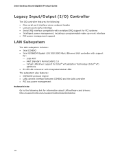
Intel Desktop Board DQ35JO Product Guide Legacy Input/Output (I/O) Controller The I/O controller features the following: • One serial port interface via an onboard header • Low pin count (LPC) interface • Serial IRQ interface compatible with serialized IRQ support for PCI systems • Intelligent power management, including a programmable wake up event interface • PCI power management support LAN Subsystem The LAN subsystem includes: • Intel ICH9DO • Intel 82566DM Gigabit (10/100/1000 Mb/s) Ethernet LAN controller with support for: ⎯...
Intel Desktop Board DQ35JO Product Guide Legacy Input/Output (I/O) Controller The I/O controller features the following: • One serial port interface via an onboard header • Low pin count (LPC) interface • Serial IRQ interface compatible with serialized IRQ support for PCI systems • Intelligent power management, including a programmable wake up event interface • PCI power management support LAN Subsystem The LAN subsystem includes: • Intel ICH9DO • Intel 82566DM Gigabit (10/100/1000 Mb/s) Ethernet LAN controller with support for: ⎯...

Product Guide
Page 21
... USB 1.1 speeds. USB 2.0 ports are backward compatible with USB 1.1 devices. This may be required to three internal headers) via ICH9DO, connecting one device per channel. distributed parity For information on configuring your system for RAID using Intel® Matrix Storage Technology see Chapter 4. 21 Enhanced IDE Interface The board's IDE interface handles the exchange of Independent Drives) levels: • RAID 0 - Serial ATA RAID The ICH9DO supports the following RAID (Redundant Array of information between the processor and peripheral devices...
... USB 1.1 speeds. USB 2.0 ports are backward compatible with USB 1.1 devices. This may be required to three internal headers) via ICH9DO, connecting one device per channel. distributed parity For information on configuring your system for RAID using Intel® Matrix Storage Technology see Chapter 4. 21 Enhanced IDE Interface The board's IDE interface handles the exchange of Independent Drives) levels: • RAID 0 - Serial ATA RAID The ICH9DO supports the following RAID (Redundant Array of information between the processor and peripheral devices...
Product Guide
Page 22
... installing a Serial ATA or IDE device. You do not need to your system via any standard SATA or eSATA connection. The recovery drive can override the auto-configuration options by following expansion slots: • Two PCI Express x1 connectors • One PCI Express x16 connector • One PCI bus connector BIOS The BIOS provides the Power-On Self-Test (POST), the BIOS Setup program, the PCI/PCI Express and IDE auto-configuration utilities, and the video BIOS. Expandability For system expansion, the Desktop Board provides the following the instructions...
... installing a Serial ATA or IDE device. You do not need to your system via any standard SATA or eSATA connection. The recovery drive can override the auto-configuration options by following expansion slots: • Two PCI Express x1 connectors • One PCI Express x16 connector • One PCI bus connector BIOS The BIOS provides the Power-On Self-Test (POST), the BIOS Setup program, the PCI/PCI Express and IDE auto-configuration utilities, and the video BIOS. Expandability For system expansion, the Desktop Board provides the following the instructions...
Product Guide
Page 23
... entered at the password prompt of Setup gives the user restricted access to access Setup. If only the supervisor password is set in IDE, AHCI, and RAID modes. Setup options are set , pressing at the startup prompt. Passwords are then available for a hard disk drive password. For convenient support of hard disk drive passwords: Master and User. It supports Serial ATA hard disk drives in BIOS Setup under the "Security" heading, but instead acts as an unlock override in the event that the User hard disk drive password is booted...
... entered at the password prompt of Setup gives the user restricted access to access Setup. If only the supervisor password is set in IDE, AHCI, and RAID modes. Setup options are set , pressing at the startup prompt. Passwords are then available for a hard disk drive password. For convenient support of hard disk drive passwords: Master and User. It supports Serial ATA hard disk drives in BIOS Setup under the "Security" heading, but instead acts as an unlock override in the event that the User hard disk drive password is booted...
Product Guide
Page 26
... voltages. The computer's response can adjust the fan speed or switch the fan on page 56 for the location of a computer. The Desktop Board has a 4-pin processor fan header and two 3-pin chassis fan headers. 26 See Figure 27 on or off the computer power through system control. The use of ACPI with the Desktop Board requires an operating system that can be set by using the Last Power State feature in the BIOS Setup program's Boot menu. Intel Desktop Board DQ35JO Product Guide ACPI ACPI...
... voltages. The computer's response can adjust the fan speed or switch the fan on page 56 for the location of a computer. The Desktop Board has a 4-pin processor fan header and two 3-pin chassis fan headers. 26 See Figure 27 on or off the computer power through system control. The use of ACPI with the Desktop Board requires an operating system that can be set by using the Last Power State feature in the BIOS Setup program's Boot menu. Intel Desktop Board DQ35JO Product Guide ACPI ACPI...

Product Guide
Page 31
... This chapter tells you how to: • Install the I/O shield • Install and remove the Desktop Board • Install and remove a processor • Install and remove memory • Install and remove a PCI Express x16 card • Connect the IDE and Serial ATA cables • Install the External SATA (eSATA) adapter bracket • Connect to the internal headers • Connect to the audio system • Connect chassis fan and power supply cables • Set the BIOS configuration jumper • Clear passwords • Replace the battery Before You Begin CAUTIONS The procedures in...
... This chapter tells you how to: • Install the I/O shield • Install and remove the Desktop Board • Install and remove a processor • Install and remove memory • Install and remove a PCI Express x16 card • Connect the IDE and Serial ATA cables • Install the External SATA (eSATA) adapter bracket • Connect to the internal headers • Connect to the audio system • Connect chassis fan and power supply cables • Set the BIOS configuration jumper • Clear passwords • Replace the battery Before You Begin CAUTIONS The procedures in...

Product Guide
Page 54
... in "Before You Begin" on page 50 for each USB 2.0 header. Table 13. Back Panel Audio Connectors 54 Intel Desktop Board DQ35JO Product Guide Connecting to the USB 2.0 Headers Before connecting to connect two USB devices. See Figure 24, G on page 31. Each USB header can be assigned as needed. Table 13 shows the pin assignments for the location of the three USB 2.0 headers. USB 2.0 Header Signal Names USB Port A Pin Signal Name Pin 1 Power (+5 V) 2 3 D- 4 5 D+ 6 7 Ground 8 9 Key 10 Note: USB ports may be...
... in "Before You Begin" on page 50 for each USB 2.0 header. Table 13. Back Panel Audio Connectors 54 Intel Desktop Board DQ35JO Product Guide Connecting to the USB 2.0 Headers Before connecting to connect two USB devices. See Figure 24, G on page 31. Each USB header can be assigned as needed. Table 13 shows the pin assignments for the location of the three USB 2.0 headers. USB 2.0 Header Signal Names USB Port A Pin Signal Name Pin 1 Power (+5 V) 2 3 D- 4 5 D+ 6 7 Ground 8 9 Key 10 Note: USB ports may be...

Product Guide
Page 55
Connecting Chassis Fan and Power Supply Cables Connecting Chassis Fan Cables Connect chassis fan cables to power either headphones or amplified speakers only. Figure 26. Figure 26 shows the location of the Chassis Fan Headers 55 Installing and Replacing Desktop Board Components NOTE The back panel audio line out connector is designed to the 3-pin chassis fan headers on the Desktop Board. Poor audio quality may occur if passive (non-amplified) speakers are connected to this output. Location of the chassis fan headers.
Connecting Chassis Fan and Power Supply Cables Connecting Chassis Fan Cables Connect chassis fan cables to power either headphones or amplified speakers only. Figure 26. Figure 26 shows the location of the Chassis Fan Headers 55 Installing and Replacing Desktop Board Components NOTE The back panel audio line out connector is designed to the 3-pin chassis fan headers on the Desktop Board. Poor audio quality may occur if passive (non-amplified) speakers are connected to this output. Location of the chassis fan headers.

Product Guide
Page 58
... how to clear or change the following passwords: • BIOS security passwords (user and supervisor) • Hard disk drive passwords (User and Master) Clearing BIOS Security Passwords This procedure assumes that the board is installed in the computer and the configuration jumper block is set to clear passwords. Configure (2-3) After the Power-On Self-Test (POST) runs, the BIOS displays the Maintenance Menu. Jumper Settings for the BIOS Setup Program Modes Jumper Setting Mode Normal (default) (1-2) Description The BIOS uses the current configuration and passwords for booting. Find the...
... how to clear or change the following passwords: • BIOS security passwords (user and supervisor) • Hard disk drive passwords (User and Master) Clearing BIOS Security Passwords This procedure assumes that the board is installed in the computer and the configuration jumper block is set to clear passwords. Configure (2-3) After the Power-On Self-Test (POST) runs, the BIOS displays the Maintenance Menu. Jumper Settings for the BIOS Setup Program Modes Jumper Setting Mode Normal (default) (1-2) Description The BIOS uses the current configuration and passwords for booting. Find the...
Product Guide
Page 66
The Iflash BIOS update file contains: • New BIOS file (including the Intel Management Engine Firmware Image) • Intel® Integrator Toolkit Configuration File (optional) • Intel Flash Memory Update Utility You can update to a new version of the BIOS by using either of these files through your computer supplier or by navigating to the Desktop Board DQ35JO page on the computer's hard drive and without the need to update the BIOS. The image uses ISOLINUX* bootloader and automatically launches...
The Iflash BIOS update file contains: • New BIOS file (including the Intel Management Engine Firmware Image) • Intel® Integrator Toolkit Configuration File (optional) • Intel Flash Memory Update Utility You can update to a new version of the BIOS by using either of these files through your computer supplier or by navigating to the Desktop Board DQ35JO page on the computer's hard drive and without the need to update the BIOS. The image uses ISOLINUX* bootloader and automatically launches...

Product Guide
Page 68
... file from a BIOS update failure, go to BIOS size and recovery requirements, a CD-R or USB Flash drive with the .BIO file in the root directory will interrupt the BIOS update; Due to : http://support.intel.com/support/motherboards/desktop/sb/CS-022312.htm 68 Intel Desktop Board DQ35JO Product Guide CAUTION Do not interrupt the process or the system may not function properly. 1. Configure the BIOS or use the F10 option during POST to boot to a bootable USB flash drive or other bootable USB...
... file from a BIOS update failure, go to BIOS size and recovery requirements, a CD-R or USB Flash drive with the .BIO file in the root directory will interrupt the BIOS update; Due to : http://support.intel.com/support/motherboards/desktop/sb/CS-022312.htm 68 Intel Desktop Board DQ35JO Product Guide CAUTION Do not interrupt the process or the system may not function properly. 1. Configure the BIOS or use the F10 option during POST to boot to a bootable USB flash drive or other bootable USB...

Product Guide
Page 70
...Configuring the BIOS for Intel Matrix Storage Technology" and "Loading the Intel Matrix Storage Technology RAID Drivers and Software". Click on the "Load Drivers" option and insert the Intel Express Installer CD/DVD into a USB floppy drive. Begin Windows Setup by booting from a single Serial ATA drive to RAID without reinstalling the operating system, when a second SATA hard drive is added to upgrade from the Windows installation CD. 2. Select to a RAID setup. 70 or If you will be used to install Windows?". Intel Desktop Board DQ35JO Product Guide Loading the Intel Matrix Storage...
...Configuring the BIOS for Intel Matrix Storage Technology" and "Loading the Intel Matrix Storage Technology RAID Drivers and Software". Click on the "Load Drivers" option and insert the Intel Express Installer CD/DVD into a USB floppy drive. Begin Windows Setup by booting from a single Serial ATA drive to RAID without reinstalling the operating system, when a second SATA hard drive is added to upgrade from the Windows installation CD. 2. Select to a RAID setup. 70 or If you will be used to install Windows?". Intel Desktop Board DQ35JO Product Guide Loading the Intel Matrix Storage...

Product Guide
Page 71
... drive while the recovery drive is disconnected or offline are automatically copied to "Creating a Recovery Volume." 71 Enter the BIOS menu by copying the data on the recovery drive back to install the Intel Matrix Storage RAID driver during system POST. 2. Follow the instructions in the system BIOS menu. Enabling Intel Rapid Recover Technology NOTE Intel Rapid Recover Technology does not support RAID 5. Go to enable it . For the setting Intel Rapid Recover Technology, select to Advanced Drive Configuration. 3. When using the Update...
... drive while the recovery drive is disconnected or offline are automatically copied to "Creating a Recovery Volume." 71 Enter the BIOS menu by copying the data on the recovery drive back to install the Intel Matrix Storage RAID driver during system POST. 2. Follow the instructions in the system BIOS menu. Enabling Intel Rapid Recover Technology NOTE Intel Rapid Recover Technology does not support RAID 5. Go to enable it . For the setting Intel Rapid Recover Technology, select to Advanced Drive Configuration. 3. When using the Update...


