
Product Guide
Page 2
... installation. Any changes or modifications to radio communications. Revision History Revision -001 Revision History First release of the Intel® Desktop Board DP45SG Product Guide Date June 2008 If an FCC declaration of conformity marking is present on the board, the following statement applies: FCC Declaration of Conformity This device complies with the instructions, may cause undesired...
... installation. Any changes or modifications to radio communications. Revision History Revision -001 Revision History First release of the Intel® Desktop Board DP45SG Product Guide Date June 2008 If an FCC declaration of conformity marking is present on the board, the following statement applies: FCC Declaration of Conformity This device complies with the instructions, may cause undesired...
Product Guide
Page 3
..., schools, computer rooms, and similar locations. It is intended for Intel® Desktop Board DP45SG. Intended Audience The Product Guide is not intended for Intended Applications All Intel Desktop Boards are arranged as follows: 1 Desktop Board Features: a summary of product features 2 Installing and Replacing Desktop Board Components: instructions on how to install the Desktop Board and other environments, such as Information Technology Equipment (I.T.E.) for use in...
..., schools, computer rooms, and similar locations. It is intended for Intel® Desktop Board DP45SG. Intended Audience The Product Guide is not intended for Intended Applications All Intel Desktop Boards are arranged as follows: 1 Desktop Board Features: a summary of product features 2 Installing and Replacing Desktop Board Components: instructions on how to install the Desktop Board and other environments, such as Information Technology Equipment (I.T.E.) for use in...

Product Guide
Page 4
Intel Desktop Board DP45SG Product Guide Conventions The following conventions are used in this manual: CAUTION Cautions warn the user about how to prevent damage to important information. Term Description GB Gigabyte (1,073,741,824 bytes) GHz Gigahertz (one billion hertz) KB Kilobyte (1024 bytes) MB Megabyte (1,048,576 bytes) Mb Megabit (1,048,576 bits) MHz Megahertz (one million hertz) iv NOTE Notes call attention to hardware or loss of some common terms used in the product guide. Terminology The table below gives descriptions of data.
Intel Desktop Board DP45SG Product Guide Conventions The following conventions are used in this manual: CAUTION Cautions warn the user about how to prevent damage to important information. Term Description GB Gigabyte (1,073,741,824 bytes) GHz Gigahertz (one billion hertz) KB Kilobyte (1024 bytes) MB Megabyte (1,048,576 bytes) Mb Megabit (1,048,576 bits) MHz Megahertz (one million hertz) iv NOTE Notes call attention to hardware or loss of some common terms used in the product guide. Terminology The table below gives descriptions of data.
Product Guide
Page 6
Intel Desktop Board DP45SG Product Guide Installing and Removing a Processor 29 Installing a Processor 29 Installing the Processor Fan Heat Sink 33 Connecting the Processor Fan Heat Sink Cable 33 Removing the ... Power Supply Cables 52 Setting the BIOS Configuration Jumper 53 Clearing Passwords 54 Replacing the Battery 55 3 Updating the BIOS Updating the BIOS with the Intel® Express BIOS Update Utility 61 Updating the BIOS with the ISO Image BIOS Update File or the Iflash Memory Update Utility 62 Obtaining the...
Intel Desktop Board DP45SG Product Guide Installing and Removing a Processor 29 Installing a Processor 29 Installing the Processor Fan Heat Sink 33 Connecting the Processor Fan Heat Sink Cable 33 Removing the ... Power Supply Cables 52 Setting the BIOS Configuration Jumper 53 Clearing Passwords 54 Replacing the Battery 55 3 Updating the BIOS Updating the BIOS with the Intel® Express BIOS Update Utility 61 Updating the BIOS with the ISO Image BIOS Update File or the Iflash Memory Update Utility 62 Obtaining the...
Product Guide
Page 8
Installing a PCI Express x16 Card 41 21. Removing the Battery 60 29. Intel Desktop Board DP45SG China RoHS Material Self Declaration Table 81 Tables 1. Feature Summary 9 2. Intel Desktop Board DP45SG Components 12 3. Front Panel CIR Receiver (Input) Header Signal Names 46 9. HD Audio ...Express x16 Card 42 22. Location of the BIOS Configuration Jumper Block 53 28. Front Panel Header Signal Names 47 12. Intel Desktop Board DP45SG Product Guide 14. Dual Channel Memory Configuration with Three DIMMs 36 17. Connecting a Serial ATA Cable 43 23. LAN Connector LEDs 15...
Installing a PCI Express x16 Card 41 21. Removing the Battery 60 29. Intel Desktop Board DP45SG China RoHS Material Self Declaration Table 81 Tables 1. Feature Summary 9 2. Intel Desktop Board DP45SG Components 12 3. Front Panel CIR Receiver (Input) Header Signal Names 46 9. HD Audio ...Express x16 Card 42 22. Location of the BIOS Configuration Jumper Block 53 28. Front Panel Header Signal Names 47 12. Intel Desktop Board DP45SG Product Guide 14. Dual Channel Memory Configuration with Three DIMMs 36 17. Connecting a Serial ATA Cable 43 23. LAN Connector LEDs 15...
Product Guide
Page 10
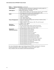
... panel • ENERGY STAR* capable Hardware monitor with: • Four fan sensing inputs used to monitor fan activity • Intel® Precision Cooling Technology fan speed control • Voltage sensing to detect out of range values • Microsoft Windows Vista*... XP Professional x64 Edition • Microsoft Windows XP Home For more information about Intel Desktop Board DP45SG, including the Technical Product Specification (TPS), BIOS updates, and device drivers, go to http://support.intel.com/support/motherboards/desktop/. 10 Intel Desktop Board DP45SG Product Guide Table 1.
... panel • ENERGY STAR* capable Hardware monitor with: • Four fan sensing inputs used to monitor fan activity • Intel® Precision Cooling Technology fan speed control • Voltage sensing to detect out of range values • Microsoft Windows Vista*... XP Professional x64 Edition • Microsoft Windows XP Home For more information about Intel Desktop Board DP45SG, including the Technical Product Specification (TPS), BIOS updates, and device drivers, go to http://support.intel.com/support/motherboards/desktop/. 10 Intel Desktop Board DP45SG Product Guide Table 1.
Product Guide
Page 14
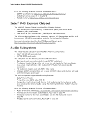
Intel Desktop Board DP45SG Product Guide Go to the following locations for more information about: • SDRAM specifications, http://www.intel.com/technology/memory/ • Installing memory, page 35 in and line out signals for the board's I /O controller hub • IDT 92HD73E audio codec The ...information about : • Audio drivers and utilities http://support.intel.com/support/motherboards/desktop/ • The location of the following components: • Intel® ICH10R I /O paths. For more information about the Intel P45 Express Chipset, go to the processor, memory, PCI ...
Intel Desktop Board DP45SG Product Guide Go to the following locations for more information about: • SDRAM specifications, http://www.intel.com/technology/memory/ • Installing memory, page 35 in and line out signals for the board's I /O controller hub • IDT 92HD73E audio codec The ...information about : • Audio drivers and utilities http://support.intel.com/support/motherboards/desktop/ • The location of the following components: • Intel® ICH10R I /O paths. For more information about the Intel P45 Express Chipset, go to the processor, memory, PCI ...

Product Guide
Page 16
... booting from a mechanical failure or the result of your system for Intel Rapid Recover Technology see Chapter 5. 16 Serial ATA Support Intel Desktop Board DP45SG supports five onboard Serial ATA channels and one eSATA channel (3.0 Gb/s) via Intel Matrix Storage Technology: • RAID 0 - Intel Desktop Board DP45SG Product Guide USB 2.0 Support The Desktop Board supports up to 12 USB 2.0 ports (six ports routed to...
... booting from a mechanical failure or the result of your system for Intel Rapid Recover Technology see Chapter 5. 16 Serial ATA Support Intel Desktop Board DP45SG supports five onboard Serial ATA channels and one eSATA channel (3.0 Gb/s) via Intel Matrix Storage Technology: • RAID 0 - Intel Desktop Board DP45SG Product Guide USB 2.0 Support The Desktop Board supports up to 12 USB 2.0 ports (six ports routed to...
Product Guide
Page 18
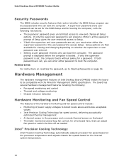
... If only the supervisor password is set, pressing at the password prompt of power supply voltages to Clearing Passwords on page 54. The board has several hardware management features including the following restrictions: • The supervisor password gives unrestricted access to access Setup. optimized thermal management... fans, that restrict whether the BIOS Setup program can be accessed and who can boot the computer. Intel Desktop Board DP45SG Product Guide Security Passwords The BIOS includes security features that can adjust fan speed or switch the fans off as needed...
... If only the supervisor password is set, pressing at the password prompt of power supply voltages to Clearing Passwords on page 54. The board has several hardware management features including the following restrictions: • The supervisor password gives unrestricted access to access Setup. optimized thermal management... fans, that restrict whether the BIOS Setup program can be accessed and who can boot the computer. Intel Desktop Board DP45SG Product Guide Security Passwords The BIOS includes security features that can adjust fan speed or switch the fans off as needed...

Product Guide
Page 20
...supply. If the standby current necessary to support multiple wake events from the PCI and/or USB buses exceeds power supply capacity, the Desktop Board may lose register settings stored in the S3 sleep state, the computer will appear to a tachometer input of the hardware monitoring and... a Magic Packet* frame, it asserts a wake-up signal that can damage the power supply and/or effect ACPI S3 sleep state functionality. Intel Desktop Board DP45SG Product Guide Fan Headers The function/operation of the fans is as needed. • All fan headers have a +12 V DC connection. Failure to ...
...supply. If the standby current necessary to support multiple wake events from the PCI and/or USB buses exceeds power supply capacity, the Desktop Board may lose register settings stored in the S3 sleep state, the computer will appear to a tachometer input of the hardware monitoring and... a Magic Packet* frame, it asserts a wake-up signal that can damage the power supply and/or effect ACPI S3 sleep state functionality. Intel Desktop Board DP45SG Product Guide Fan Headers The function/operation of the fans is as needed. • All fan headers have a +12 V DC connection. Failure to ...
Product Guide
Page 22
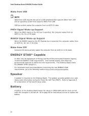
...When the PME# signal on the Desktop Board keeps the values in CMOS RAM and the clock current when the computer is asserted, the computer wakes from an ACPI S3 state. ENERGY STAR* Capable In 2007, the US Department of the board's beep codes. For information and ...battery. 22 PME# Signal Wake-up Support When the WAKE# signal on the Desktop Board. Wake from CIR Consumer IR device activity wakes the computer from USB. This Desktop Board meets the ENERGY STAR Category C. Intel Desktop Board DP45SG Product Guide Wake from USB NOTE Wake from USB requires the use of a USB peripheral that...
...When the PME# signal on the Desktop Board keeps the values in CMOS RAM and the clock current when the computer is asserted, the computer wakes from an ACPI S3 state. ENERGY STAR* Capable In 2007, the US Department of the board's beep codes. For information and ...battery. 22 PME# Signal Wake-up Support When the WAKE# signal on the Desktop Board. Wake from CIR Consumer IR device activity wakes the computer from USB. This Desktop Board meets the ENERGY STAR Category C. Intel Desktop Board DP45SG Product Guide Wake from USB NOTE Wake from USB requires the use of a USB peripheral that...

Product Guide
Page 26
Intel Desktop Board DP45SG Product Guide Installation Precautions When you can ensure that the calculated ... personnel. To avoid injury, be careful of noncompliance with regional laws and regulations. For information about the Desktop Board's regulatory compliance, go to wires that could cause a short circuit Observe all warnings and cautions in this... supply output. If you to refer computer servicing to find out how you install and test the Intel Desktop Board, observe all warnings and cautions that instruct you do not follow the instructions in the installation instructions....
Intel Desktop Board DP45SG Product Guide Installation Precautions When you can ensure that the calculated ... personnel. To avoid injury, be careful of noncompliance with regional laws and regulations. For information about the Desktop Board's regulatory compliance, go to wires that could cause a short circuit Observe all warnings and cautions in this... supply output. If you to refer computer servicing to find out how you install and test the Intel Desktop Board, observe all warnings and cautions that instruct you do not follow the instructions in the installation instructions....

Product Guide
Page 28
... removing the Desktop Board. Figure 5. Intel Desktop Board DP45SG Mounting Screw Hole Locations 28 Disconnect the computer from its power source before you open the computer can result in personal injury or equipment damage. Refer to disconnect the power before performing the procedures described here. Failure to your chassis manual for Intel Desktop Board DP45SG. Intel Desktop Board DP45SG Product Guide Installing and Removing the Desktop Board CAUTION...
... removing the Desktop Board. Figure 5. Intel Desktop Board DP45SG Mounting Screw Hole Locations 28 Disconnect the computer from its power source before you open the computer can result in personal injury or equipment damage. Refer to disconnect the power before performing the procedures described here. Failure to your chassis manual for Intel Desktop Board DP45SG. Intel Desktop Board DP45SG Product Guide Installing and Removing the Desktop Board CAUTION...

Product Guide
Page 30
Lift the Load Plate 4. Figure 8. Figure 7. Lift the load plate (Figure 7, A). Always replace the socket cover if the processor is removed from the load plate (Figure 8). Remove the Protective Socket Cover 30 Do not touch the socket contacts (Figure 7, B). Remove the plastic protective socket cover from the socket. Do not discard the protective socket cover. Intel Desktop Board DP45SG Product Guide 3.
Lift the Load Plate 4. Figure 8. Figure 7. Lift the load plate (Figure 7, A). Always replace the socket cover if the processor is removed from the load plate (Figure 8). Remove the Protective Socket Cover 30 Do not touch the socket contacts (Figure 7, B). Remove the plastic protective socket cover from the socket. Do not discard the protective socket cover. Intel Desktop Board DP45SG Product Guide 3.

Product Guide
Page 32
Figure 11. Intel Desktop Board DP45SG Product Guide 7. Pressing down on the load plate (Figure 11, A), close and engage the socket lever (Figure 11, B). Close the Load Plate 32
Figure 11. Intel Desktop Board DP45SG Product Guide 7. Pressing down on the load plate (Figure 11, A), close and engage the socket lever (Figure 11, B). Close the Load Plate 32

Product Guide
Page 34
Intel Desktop Board DP45SG Product Guide Removing the Processor For instructions on the bottom of the heat sink cover (Figure 13, A). 3. Figure 13. Installing the ICH Heat Sink Decorative Cover 34 ...
Intel Desktop Board DP45SG Product Guide Removing the Processor For instructions on the bottom of the heat sink cover (Figure 13, A). 3. Figure 13. Installing the ICH Heat Sink Decorative Cover 34 ...
Product Guide
Page 36
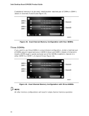
Intel Desktop Board DP45SG Product Guide If additional memory is to use three DIMMs in a dual-channel configuration, install a matched pair of DIMMs equal in speed and size in DIMM 0 (blue) ...
Intel Desktop Board DP45SG Product Guide If additional memory is to use three DIMMs in a dual-channel configuration, install a matched pair of DIMMs equal in speed and size in DIMM 0 (blue) ...

Product Guide
Page 38
...(s) are firmly in Figure 18). 7. When the DIMM is inserted, push down on page 25. 2. Turn off all peripheral devices connected to the open position. 5. Intel Desktop Board DP45SG Product Guide To install a DIMM, follow these steps: 1. Installing a DIMM 4. Replace the computer's cover and reconnect the AC power cord. 38 Insert the bottom edge of the...
...(s) are firmly in Figure 18). 7. When the DIMM is inserted, push down on page 25. 2. Turn off all peripheral devices connected to the open position. 5. Intel Desktop Board DP45SG Product Guide To install a DIMM, follow these steps: 1. Installing a DIMM 4. Replace the computer's cover and reconnect the AC power cord. 38 Insert the bottom edge of the...

Product Guide
Page 40
... Cards 40 Depending on the over-current protection of the power supply, certain Desktop Board components and/or traces may result across the connector pins. Intel Desktop Board DP45SG Product Guide Installing and Removing a PCI Express x16 Card CAUTION When installing a PCI Express card on the Desktop Board, ensure that the card is not fully seated in the secondary connector...
... Cards 40 Depending on the over-current protection of the power supply, certain Desktop Board components and/or traces may result across the connector pins. Intel Desktop Board DP45SG Product Guide Installing and Removing a PCI Express x16 Card CAUTION When installing a PCI Express card on the Desktop Board, ensure that the card is not fully seated in the secondary connector...

Product Guide
Page 42
Intel Desktop Board DP45SG Product Guide Removing a PCI Express x16 Card Follow these instructions to the chassis back panel. 3. This will release the card from a connector: 1. Pull the card straight up. Removing a PCI Express x16 Card 42 Observe the precautions in the notch. Push the card ejector lever down using the tip of a pencil or similar tool (Figure 21, B) in "Before You Begin" on page 25. 2. Remove the screw (Figure 21, A) that secures the card's metal bracket to remove a PCI Express x16 card from the connector (C). 4. Figure 21.
Intel Desktop Board DP45SG Product Guide Removing a PCI Express x16 Card Follow these instructions to the chassis back panel. 3. This will release the card from a connector: 1. Pull the card straight up. Removing a PCI Express x16 Card 42 Observe the precautions in the notch. Push the card ejector lever down using the tip of a pencil or similar tool (Figure 21, B) in "Before You Begin" on page 25. 2. Remove the screw (Figure 21, A) that secures the card's metal bracket to remove a PCI Express x16 card from the connector (C). 4. Figure 21.
