
Product Guide
Page 5
...Desktop Board Features Desktop Board Components 11 Processor ...13 Main Memory...13 Intel® P45 Express Chipset 14 Audio Subsystem 14 LAN Subsystem 15 USB 2.0 Support 16 Serial ATA Support 16 Serial ATA RAID 16 Intel® Rapid Recover Technology (Intel...Passwords 18 Hardware Management 18 Hardware Monitoring and Fan Speed Control 18 Intel® Precision Cooling Technology 18 Chassis Intrusion 19 Power Management 19 Software... Real-Time Clock 23 2 Installing and Replacing Desktop Board Components Before You Begin 25 Installation Precautions 26 Prevent Power Supply Overload ...
...Desktop Board Features Desktop Board Components 11 Processor ...13 Main Memory...13 Intel® P45 Express Chipset 14 Audio Subsystem 14 LAN Subsystem 15 USB 2.0 Support 16 Serial ATA Support 16 Serial ATA RAID 16 Intel® Rapid Recover Technology (Intel...Passwords 18 Hardware Management 18 Hardware Monitoring and Fan Speed Control 18 Intel® Precision Cooling Technology 18 Chassis Intrusion 19 Power Management 19 Software... Real-Time Clock 23 2 Installing and Replacing Desktop Board Components Before You Begin 25 Installation Precautions 26 Prevent Power Supply Overload ...
Product Guide
Page 7
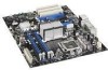
Lift the Load Plate 30 8. Remove the Protective Socket Cover 30 9. Close the Load Plate 32 12. Installing the I/O Shield 27 5. Installing the ICH Heat Sink Decorative Cover 34 vii Intel Desktop Board DP45SG Components 11 2. Intel Desktop Board DP45SG Mounting Screw Hole Locations 28 6. Connecting the Processor Fan Heat Sink Cable 33 13. Location of Hazardous Substances (RoHS 79...
Lift the Load Plate 30 8. Remove the Protective Socket Cover 30 9. Close the Load Plate 32 12. Installing the I/O Shield 27 5. Installing the ICH Heat Sink Decorative Cover 34 vii Intel Desktop Board DP45SG Components 11 2. Intel Desktop Board DP45SG Mounting Screw Hole Locations 28 6. Connecting the Processor Fan Heat Sink Cable 33 13. Location of Hazardous Substances (RoHS 79...

Product Guide
Page 25
... modems before you open the computer or perform any of the computer chassis. 25 2 Installing and Replacing Desktop Board Components This chapter tells you how to: • Install the I/O shield • Install and remove the Desktop Board • Install and remove a processor • Install the ICH heat sink decorative cover (optional) ... of the procedures described in this chapter only at an ESD workstation using and modifying electronic equipment. Some circuitry on the board can continue to operate even though the front panel power button is not available, you can damage components.
... modems before you open the computer or perform any of the computer chassis. 25 2 Installing and Replacing Desktop Board Components This chapter tells you how to: • Install the I/O shield • Install and remove the Desktop Board • Install and remove a processor • Install the ICH heat sink decorative cover (optional) ... of the procedures described in this chapter only at an ESD workstation using and modifying electronic equipment. Some circuitry on the board can continue to operate even though the front panel power button is not available, you can damage components.

Product Guide
Page 27
... it fits tightly and securely. Installing the I /O shield before installing the Desktop Board in the chassis. Place the shield inside the chassis as shown in the chassis, the shield blocks radio frequency transmissions, protects internal components from the chassis supplier. If the shield does not fit, obtain a properly sized shield from dust and foreign objects, and promotes...
... it fits tightly and securely. Installing the I /O shield before installing the Desktop Board in the chassis. Place the shield inside the chassis as shown in the chassis, the shield blocks radio frequency transmissions, protects internal components from the chassis supplier. If the shield does not fit, obtain a properly sized shield from dust and foreign objects, and promotes...

Product Guide
Page 49
...: USB ports may be used to the cable. Table 15. Table 14 shows the pin assignments and signal names for the header. Table 14. Use a shielded cable that have an unshielded cable attached to a USB port might not meet FCC Class B requirements, even if no device or a low-speed USB device... that meets the requirements for the location of the USB 2.0 headers. Serial Port Header See Figure 23, E for a full-speed USB device. Installing and Replacing Desktop Board Components USB 2.0 Headers Figure 23, J shows the location of the serial port header.
...: USB ports may be used to the cable. Table 15. Table 14 shows the pin assignments and signal names for the header. Table 14. Use a shielded cable that have an unshielded cable attached to a USB port might not meet FCC Class B requirements, even if no device or a low-speed USB device... that meets the requirements for the location of the USB 2.0 headers. Serial Port Header See Figure 23, E for a full-speed USB device. Installing and Replacing Desktop Board Components USB 2.0 Headers Figure 23, J shows the location of the serial port header.

Product Guide
Page 83
... or peripherals, as applicable, are not Class B EMC compliant before integration, then EMC testing may be required on a representative sample of certifications • External I/O cable shielding and filtering • Mounting, grounding, and bonding requirements • Keying connectors when mating the wrong connectors could be hazardous If the power supply and other...
... or peripherals, as applicable, are not Class B EMC compliant before integration, then EMC testing may be required on a representative sample of certifications • External I/O cable shielding and filtering • Mounting, grounding, and bonding requirements • Keying connectors when mating the wrong connectors could be hazardous If the power supply and other...