Product Guide
Page 5
...Desktop Board Features Supported Operating Systems 10 Desktop Board Components 11 Processor ...13 Main Memory...13 Intel® P35 Express Chipset 14 Audio Subsystem 15 Legacy Input/Output (I/O) Controller 15 LAN Subsystem 16 RJ-45 LAN Connector LEDs 16 Hi-Speed USB 2.0 Support 17 Enhanced IDE Interface 17 Serial ATA...18 Serial ATA RAID 18 Intel... ENERGY STAR* Capable 24 Speaker...24 Battery ...24 Real-Time Clock 24 2 Installing and Replacing Desktop Board Components Before You Begin 25 Installation Precautions 26 Prevent Power Supply Overload 26 Observe Safety and Regulatory ...
...Desktop Board Features Supported Operating Systems 10 Desktop Board Components 11 Processor ...13 Main Memory...13 Intel® P35 Express Chipset 14 Audio Subsystem 15 Legacy Input/Output (I/O) Controller 15 LAN Subsystem 16 RJ-45 LAN Connector LEDs 16 Hi-Speed USB 2.0 Support 17 Enhanced IDE Interface 17 Serial ATA...18 Serial ATA RAID 18 Intel... ENERGY STAR* Capable 24 Speaker...24 Battery ...24 Real-Time Clock 24 2 Installing and Replacing Desktop Board Components Before You Begin 25 Installation Precautions 26 Prevent Power Supply Overload 26 Observe Safety and Regulatory ...
Product Guide
Page 6
Intel Desktop Board DP35DP Product Guide Installing a Processor 29 Installing the Processor Fan Heat Sink 32 Connecting the Processor Fan Heat Sink Cable 33 Removing the Processor 34 Installing ... the Alternate Front Panel Power LED Header 49 Connecting to the Front Panel Header 50 Connecting to the USB 2.0 Headers 50 Connecting to the Flexible Audio System 51 Connecting Chassis Fan and Power Supply Cables 52 Connecting Chassis Fan Cables 52 Connecting Supply Power Cables 53 Setting the BIOS Configuration Jumper...
Intel Desktop Board DP35DP Product Guide Installing a Processor 29 Installing the Processor Fan Heat Sink 32 Connecting the Processor Fan Heat Sink Cable 33 Removing the Processor 34 Installing ... the Alternate Front Panel Power LED Header 49 Connecting to the Front Panel Header 50 Connecting to the USB 2.0 Headers 50 Connecting to the Flexible Audio System 51 Connecting Chassis Fan and Power Supply Cables 52 Connecting Chassis Fan Cables 52 Connecting Supply Power Cables 53 Setting the BIOS Configuration Jumper...
Product Guide
Page 7
...the Processor 31 11. Use DDR2 DIMMs 37 17. Connecting a Serial ATA Cable 44 22. Back Panel Audio Connectors 51 25. LAN Connector LEDs 16 3. Desktop Board DP35DP Mounting Screw Hole Locations 28 6. Dual Channel Memory Configuration with Four DIMMs 35 15. Connecting the IDE Cable... 23 4. Close the Load Plate 32 12. Removing a PCI Express x16 Card 41 20. Contents 5 Configuring for Intel® Rapid Recover Technology Enabling Intel Rapid Recover Technology 67 Creating a Recovery Volume 68 Creating a Recovery Volume Using the RAID Option ROM 68 Creating a Recovery...
...the Processor 31 11. Use DDR2 DIMMs 37 17. Connecting a Serial ATA Cable 44 22. Back Panel Audio Connectors 51 25. LAN Connector LEDs 16 3. Desktop Board DP35DP Mounting Screw Hole Locations 28 6. Dual Channel Memory Configuration with Four DIMMs 35 15. Connecting the IDE Cable... 23 4. Close the Load Plate 32 12. Removing a PCI Express x16 Card 41 20. Contents 5 Configuring for Intel® Rapid Recover Technology Enabling Intel Rapid Recover Technology 67 Creating a Recovery Volume 68 Creating a Recovery Volume Using the RAID Option ROM 68 Creating a Recovery...
Product Guide
Page 8
... 18. Front Panel Intel High Definition Audio Header Signal Names 47 7. Alternate Front Panel Power LED Header 49 12. LAN Connector LEDs 17 4. BIOS Error Messages 71 17. Jumper Settings for the BIOS Setup Program Modes 55 15. Serial Port Header Signal Names 49 10. EMC Regulations 80 20. Intel Desktop Board DP35DP Product Guide 26.
... 18. Front Panel Intel High Definition Audio Header Signal Names 47 7. Alternate Front Panel Power LED Header 49 12. LAN Connector LEDs 17 4. BIOS Error Messages 71 17. Jumper Settings for the BIOS Setup Program Modes 55 15. Serial Port Header Signal Names 49 10. EMC Regulations 80 20. Intel Desktop Board DP35DP Product Guide 26.
Product Guide
Page 9
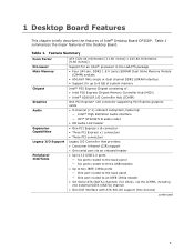
...Desktop Board. Table 1 summarizes the major features of : • Intel P35 Express Chipset Memory Controller Hub (MCH) • Intel® 82801IR I/O Controller Hub (ICH9R) One PCI Express* x16 connector supporting PCI Express graphics cards • 8-channel (7.1) onboard subsystem, featuring: ― Intel® High Definition Audio interface ― IDT* STAC9271D audio codec • HD Audio...• One IDE interface with ATA-66/100 support (two devices) continued 9 Table 1. 1 Desktop Board Features This chapter briefly describes the features of Intel® Desktop Board DP35DP.
...Desktop Board. Table 1 summarizes the major features of : • Intel P35 Express Chipset Memory Controller Hub (MCH) • Intel® 82801IR I/O Controller Hub (ICH9R) One PCI Express* x16 connector supporting PCI Express graphics cards • 8-channel (7.1) onboard subsystem, featuring: ― Intel® High Definition Audio interface ― IDT* STAC9271D audio codec • HD Audio...• One IDE interface with ATA-66/100 support (two devices) continued 9 Table 1. 1 Desktop Board Features This chapter briefly describes the features of Intel® Desktop Board DP35DP.
Product Guide
Page 13
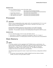
... Go to the following links for Desktop Board DP35DP, http://www.intel.com/go /findCPU • Audio software and utilities http://www.intel.com/design/motherbd • LAN software and drivers http://www.intel.com/design/motherbd Processor CAUTION Failure to...(SPD) data structure. Desktop Board DP35DP supports an Intel processor in Chapter 2 • Supported processors for more information about : • Desktop Board DP35DP http://www.intel.com/design/motherbd http://support.intel.com/support/motherboards/desktop • Supported processors http://www.intel.com/go /findCPU Main...
... Go to the following links for Desktop Board DP35DP, http://www.intel.com/go /findCPU • Audio software and utilities http://www.intel.com/design/motherbd • LAN software and drivers http://www.intel.com/design/motherbd Processor CAUTION Failure to...(SPD) data structure. Desktop Board DP35DP supports an Intel processor in Chapter 2 • Supported processors for more information about : • Desktop Board DP35DP http://www.intel.com/design/motherbd http://support.intel.com/support/motherboards/desktop • Supported processors http://www.intel.com/go /findCPU Main...
Product Guide
Page 15
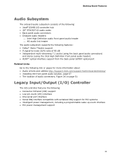
Desktop Board Features Audio Subsystem The onboard audio subsystem consists of the following: • Intel® ICH9R I/O controller hub • IDT STAC9271D audio codec • Back panel audio connectors • Onboard audio headers: ⎯ Intel High Definition audio front panel audio header ⎯ HD audio link header The audio ... pages for more information about: • Audio drivers and utilities http://support.intel.com/support/motherboards/desktop/ • Installing the front panel audio solution, page 47 • The location of audio connectors, Figure 24 on page 51 Legacy Input...
Desktop Board Features Audio Subsystem The onboard audio subsystem consists of the following: • Intel® ICH9R I/O controller hub • IDT STAC9271D audio codec • Back panel audio connectors • Onboard audio headers: ⎯ Intel High Definition audio front panel audio header ⎯ HD audio link header The audio ... pages for more information about: • Audio drivers and utilities http://support.intel.com/support/motherboards/desktop/ • Installing the front panel audio solution, page 47 • The location of audio connectors, Figure 24 on page 51 Legacy Input...
Product Guide
Page 25
... damage components. If such a station is off. 2 Installing and Replacing Desktop Board Components This chapter tells you how to: • Install the I/O shield • Install and remove the Desktop Board • Install and remove a processor • Install and remove memory ...• Install and remove a PCI Express x16 card • Connect the IDE and Serial ATA cables • Install the External SATA (eSATA) adapter bracket • Connect to the internal headers • Connect to the flexible audio...
... damage components. If such a station is off. 2 Installing and Replacing Desktop Board Components This chapter tells you how to: • Install the I/O shield • Install and remove the Desktop Board • Install and remove a processor • Install and remove memory ...• Install and remove a PCI Express x16 card • Connect the IDE and Serial ATA cables • Install the External SATA (eSATA) adapter bracket • Connect to the internal headers • Connect to the flexible audio...

Product Guide
Page 46
Internal Headers 46 Figure 23 shows the location of the internal headers. Intel Desktop Board DP35DP Product Guide Connecting to the Internal Headers Before connecting cables to the internal headers, observe the precautions in "Before You Begin" on page 25. Item Description A HD Audio Link B IEEE 1394a C Front panel audio D Back Panel CIR Emitter (Output) E Serial port Item Description F Front Panel CIR Receiver (Input) G Chassis Intrusion H Alternate front panel power LED I Front panel J USB 2.0 (3) Figure 23.
Internal Headers 46 Figure 23 shows the location of the internal headers. Intel Desktop Board DP35DP Product Guide Connecting to the Internal Headers Before connecting cables to the internal headers, observe the precautions in "Before You Begin" on page 25. Item Description A HD Audio Link B IEEE 1394a C Front panel audio D Back Panel CIR Emitter (Output) E Serial port Item Description F Front Panel CIR Receiver (Input) G Chassis Intrusion H Alternate front panel power LED I Front panel J USB 2.0 (3) Figure 23.

Product Guide
Page 47
.... Table 5 shows the pin assignments for the location of the front panel audio header. Table 4. Table 6. Installing and Replacing Desktop Board Components Connecting to the IEEE 1394a Header See Figure 23, B for the front panel audio header. Table 4 shows the pin assignments for Intel® High Definition Audio Figure 23, C shows the location of the HD...
.... Table 5 shows the pin assignments for the location of the front panel audio header. Table 4. Table 6. Installing and Replacing Desktop Board Components Connecting to the IEEE 1394a Header See Figure 23, B for the front panel audio header. Table 4 shows the pin assignments for Intel® High Definition Audio Figure 23, C shows the location of the HD...
Product Guide
Page 48
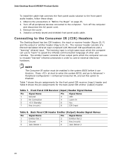
...No Connection 5 +5 V Standby 7 Key (no pin) 6 Jack Detect 2 48 Intel Desktop Board DP35DP Product Guide To install the cable that connects the front panel audio solution to the Consumer IR (CIR) Headers The Desktop Board has two CIR headers: the input or receiver header (Figure 23, F) and the output... input. Turn off all peripheral devices connected to Enabled. Install a correctly keyed and shielded front panel audio cable. Connecting to the front panel audio header, follow these steps: 1. The emitter header consists of two output ports which the computer can function.
...No Connection 5 +5 V Standby 7 Key (no pin) 6 Jack Detect 2 48 Intel Desktop Board DP35DP Product Guide To install the cable that connects the front panel audio solution to the Consumer IR (CIR) Headers The Desktop Board has two CIR headers: the input or receiver header (Figure 23, F) and the output... input. Turn off all peripheral devices connected to Enabled. Install a correctly keyed and shielded front panel audio cable. Connecting to the front panel audio header, follow these steps: 1. The emitter header consists of two output ports which the computer can function.
Product Guide
Page 51
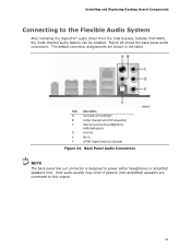
... shown in the table. Figure 24 shows the back panel audio connectors. Back Panel Audio Connectors NOTE The back panel line out connector is designed to this output. 51 Installing and Replacing Desktop Board Components Connecting to the Flexible Audio System After installing the SigmaTel* audio driver from the Intel Express Installer DVD-ROM, the multi-channel...
... shown in the table. Figure 24 shows the back panel audio connectors. Back Panel Audio Connectors NOTE The back panel line out connector is designed to this output. 51 Installing and Replacing Desktop Board Components Connecting to the Flexible Audio System After installing the SigmaTel* audio driver from the Intel Express Installer DVD-ROM, the multi-channel...


