Product Guide
Page 7
Desktop Board DP35DP Components 11 2. Remove the Processor from the Protective Processor Cover 31 10. Connecting the Processor Fan Heat Sink Cable to the Processor Fan Header ..........33 13. Connecting the IDE Cable 43 21. Location of the Chassis Fan Headers 52 vii Desktop Board DP35DP...x16 Card 41 20. Contents 5 Configuring for Intel® Rapid Recover Technology Enabling Intel Rapid Recover Technology 67 Creating a Recovery Volume...Lead-Free Desktop Board 78 EMC Regulations 80 Ensure Electromagnetic Compatibility (EMC) Compliance 81 Product Certifications 82 Board-Level ...
Desktop Board DP35DP Components 11 2. Remove the Processor from the Protective Processor Cover 31 10. Connecting the Processor Fan Heat Sink Cable to the Processor Fan Header ..........33 13. Connecting the IDE Cable 43 21. Location of the Chassis Fan Headers 52 vii Desktop Board DP35DP...x16 Card 41 20. Contents 5 Configuring for Intel® Rapid Recover Technology Enabling Intel Rapid Recover Technology 67 Creating a Recovery Volume...Lead-Free Desktop Board 78 EMC Regulations 80 Ensure Electromagnetic Compatibility (EMC) Compliance 81 Product Certifications 82 Board-Level ...
Product Guide
Page 17
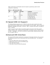
Enhanced IDE Interface The board's IDE interface handles the exchange of information between the processor and peripheral devices such as CD-ROM drives) • ...link is established LAN activity is operating. USB 2.0 ports are backward compatible with USB 1.1 devices. Desktop Board Features Table 3 describes the LED states when the board is powered up and the LAN subsystem is occurring 10 Mb/s data... rate 100 Mb/s data rate 1000 Mb/s data rate Hi-Speed USB 2.0 Support The Desktop Board supports up to 12 USB 2.0 ports (six ports routed to the back panel and six ports routed...
Enhanced IDE Interface The board's IDE interface handles the exchange of information between the processor and peripheral devices such as CD-ROM drives) • ...link is established LAN activity is operating. USB 2.0 ports are backward compatible with USB 1.1 devices. Desktop Board Features Table 3 describes the LED states when the board is powered up and the LAN subsystem is occurring 10 Mb/s data... rate 100 Mb/s data rate 1000 Mb/s data rate Hi-Speed USB 2.0 Support The Desktop Board supports up to 12 USB 2.0 ports (six ports routed to the back panel and six ports routed...
Product Guide
Page 20
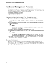
...Desktop Board. Intel Desktop Board DP35DP Product Guide Hardware Management Features The hardware management features of Desktop Board DP35DP enable the board to be installed in the Channel A, DIMM 0 socket to enable Intel Quiet System Technology. • Fan speed controllers and sensors integrated into the ICH9R • Thermal sensors in the processor... rises above and below acceptable values • Intel Quiet System Technology fan speed control, delivering acoustically-optimized thermal management NOTE Memory must be compatible with the Wired for the location of the chassis...
...Desktop Board. Intel Desktop Board DP35DP Product Guide Hardware Management Features The hardware management features of Desktop Board DP35DP enable the board to be installed in the Channel A, DIMM 0 socket to enable Intel Quiet System Technology. • Fan speed controllers and sensors integrated into the ICH9R • Thermal sensors in the processor... rises above and below acceptable values • Intel Quiet System Technology fan speed control, delivering acoustically-optimized thermal management NOTE Memory must be compatible with the Wired for the location of the chassis...

Product Guide
Page 53
...in damage to the board or the system may result in "Before You Begin" on the Desktop Board is backwards compatible with ATX12V power supplies with 2 x 10 connectors. Connect the main power supply cable to the 2 x 2 pin connector. 53 Installing and Replacing Desktop Board Components Connecting Supply ...Failure to use an appropriate power supply and/or not connecting the 12 V (2 x 2 pin) power connector to the Desktop Board may not function properly. Connect the 12 V processor core voltage power supply cable to the 2 x 12 pin connector. 3. The 2 x 12 pin main power connector on ...
...in damage to the board or the system may result in "Before You Begin" on the Desktop Board is backwards compatible with ATX12V power supplies with 2 x 10 connectors. Connect the main power supply cable to the 2 x 2 pin connector. 53 Installing and Replacing Desktop Board Components Connecting Supply ...Failure to use an appropriate power supply and/or not connecting the 12 V (2 x 2 pin) power connector to the Desktop Board may not function properly. Connect the 12 V processor core voltage power supply cable to the 2 x 12 pin connector. 3. The 2 x 12 pin main power connector on ...


