
Smart Response Technology User Guide
Page 1
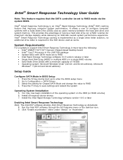
...the LGA1155 package • System BIOS with SATA mode set to save settings and restart the system Operating System Installation 5. Go to RAID • Intel Rapid Storage Technology software 10.5 version release or later • Single Hard Disk Drive (HDD) or multiple HDD...used as a single drive letter solution; Install the Intel Rapid Storage Technology software version 10.5 or later Enabling Intel Smart Response Technology Note: The Intel RST software denotes Intel Smart Response Technology as cache memory between the hard disk drive and system memory. It allows a user to configure ...
...the LGA1155 package • System BIOS with SATA mode set to save settings and restart the system Operating System Installation 5. Go to RAID • Intel Rapid Storage Technology software 10.5 version release or later • Single Hard Disk Drive (HDD) or multiple HDD...used as a single drive letter solution; Install the Intel Rapid Storage Technology software version 10.5 or later Enabling Intel Smart Response Technology Note: The Intel RST software denotes Intel Smart Response Technology as cache memory between the hard disk drive and system memory. It allows a user to configure ...
Technical Product Specification
Page 19
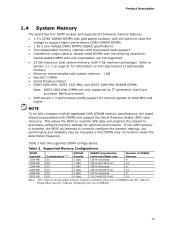
...sided DIMMs with the following restriction: Double-sided DIMMs with x16 organization are only supported by 3rd generation Intel Core processor family processors • XMP version 1.3 performance profile support for memory speeds of 1600 MHz and higher NOTE To be fully compliant with all applicable DDR SDRAM... DIMMs Note: DDR3 1600 MHz DIMMs are not supported. • 32 GB maximum total system memory (with DIMMs that support the Serial Presence Detect (SPD) data structure. If non-SPD memory is installed, the BIOS will attempt to Section 2.1.1 on the total amount of SDRAM). 19 Table 3...
...sided DIMMs with the following restriction: Double-sided DIMMs with x16 organization are only supported by 3rd generation Intel Core processor family processors • XMP version 1.3 performance profile support for memory speeds of 1600 MHz and higher NOTE To be fully compliant with all applicable DDR SDRAM... DIMMs Note: DDR3 1600 MHz DIMMs are not supported. • 32 GB maximum total system memory (with DIMMs that support the Serial Presence Detect (SPD) data structure. If non-SPD memory is installed, the BIOS will attempt to Section 2.1.1 on the total amount of SDRAM). 19 Table 3...

Technical Product Specification
Page 20
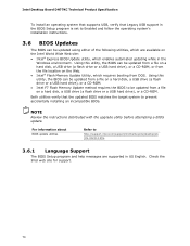
...channel to dual channel operation; This mode is used when only a single DIMM is enabled when the installed memory capacities of DRAM memory. The bottommost DRAM memory (the memory that is nearest to the 8 GB address space limit), if any, is equivalent to the other... slowest memory timing will be used . • Flex mode. the topmost DRAM memory (the memory that is lowest within the system memory map) is necessary to single channel operation. Intel Desktop Board DH77KC Technical Product Specification For information about ... Tested Memory Refer to : http://www.intel.com/...
...channel to dual channel operation; This mode is used when only a single DIMM is enabled when the installed memory capacities of DRAM memory. The bottommost DRAM memory (the memory that is nearest to the 8 GB address space limit), if any, is equivalent to the other... slowest memory timing will be used . • Flex mode. the topmost DRAM memory (the memory that is lowest within the system memory map) is necessary to single channel operation. Intel Desktop Board DH77KC Technical Product Specification For information about ... Tested Memory Refer to : http://www.intel.com/...

Technical Product Specification
Page 21
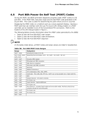
For best memory performance always install memory in installation order from DIMM 1 to DIMM 4. Product Description Figure 3 illustrates the memory channel and DIMM configuration. Memory Channel and DIMM Configuration NOTE The DIMM sockets are labeled in the blue DIMM sockets (DIMM 1 and DIMM 2) if installing only two DIMMs on your board 21 Figure 3.
For best memory performance always install memory in installation order from DIMM 1 to DIMM 4. Product Description Figure 3 illustrates the memory channel and DIMM configuration. Memory Channel and DIMM Configuration NOTE The DIMM sockets are labeled in the blue DIMM sockets (DIMM 1 and DIMM 2) if installing only two DIMMs on your board 21 Figure 3.

Technical Product Specification
Page 41
On a system that has 32 GB of system memory installed, it is not possible to use all of the installed memory due to reclaim the physical memory overlapped by the memory mapped I /O that is no overlap of the system memory map. These functions include the following: • BIOS/SPI Flash device (32 Mbit) • Local APIC (19 MB...
On a system that has 32 GB of system memory installed, it is not possible to use all of the installed memory due to reclaim the physical memory overlapped by the memory mapped I /O that is no overlap of the system memory map. These functions include the following: • BIOS/SPI Flash device (32 Mbit) • Local APIC (19 MB...

Technical Product Specification
Page 69
...Play operating system can obtain the system types, capabilities, operational status, and installation dates for managing computers in the BIOS Setup program.) 6. POST completes. 5. Additional board information can be access by using Intel® Integrator Toolkit. 69 When you to configure the operating system. (... BIOS revision level • Fixed-system data, such as peripherals, serial numbers, and asset tags • Resource data, such as memory size, cache size, and processor speed • Dynamic data, such as event detection and error logging Non-Plug and Play operating systems...
...Play operating system can obtain the system types, capabilities, operational status, and installation dates for managing computers in the BIOS Setup program.) 6. POST completes. 5. Additional board information can be access by using Intel® Integrator Toolkit. 69 When you to configure the operating system. (... BIOS revision level • Fixed-system data, such as peripherals, serial numbers, and asset tags • Resource data, such as memory size, cache size, and processor speed • Dynamic data, such as event detection and error logging Non-Plug and Play operating systems...
Technical Product Specification
Page 70
...BIOS can be updated from a file on a hard disk, a USB drive (a flash drive or a USB hard drive), or a CD-ROM. • Intel F7 Flash Memory Update method requires the BIOS to be updated from a file on a hard disk, a USB drive (a flash drive or a USB hard drive), or a CD... supported in the Windows environment. Using this utility, the BIOS can be updated from DOS. Check the Intel web site for support. 70 Intel Desktop Board DH77KC Technical Product Specification To install an operating system that supports USB, verify that the updated BIOS matches the target system to prevent accidentally...
...BIOS can be updated from a file on a hard disk, a USB drive (a flash drive or a USB hard drive), or a CD-ROM. • Intel F7 Flash Memory Update method requires the BIOS to be updated from a file on a hard disk, a USB drive (a flash drive or a USB hard drive), or a CD... supported in the Windows environment. Using this utility, the BIOS can be updated from DOS. Check the Intel web site for support. 70 Intel Desktop Board DH77KC Technical Product Specification To install an operating system that supports USB, verify that the updated BIOS matches the target system to prevent accidentally...
Technical Product Specification
Page 79
...Refer to S5. S3, etc. Start with the Low Pin Count (LPC) Debug header or a POST card that critical since consoles should be installed in one of the LPC Debug header in hexadecimal. Table 50. BDS Output Devices: All output consoles. If the POST fails, execution stops and ... use 79 Not that can interface with PCI. S2, 0x30 - Security (SEC) phase PEI phase pre MRC execution 0x21 - 0x29 0x2A - 0x2F 0x31 - 0x35 MRC Memory detection PEI phase post MRC execution Recovery 0x36 - 0x3F 0x41 - 0x4F 0x50 - 0x5F 0x60 - 0x6F 0x70 - 0x7F 0x80 - 0x8F 0x90 - 0x9F 0xA0 - 0xAF 0xB0 -...
...Refer to S5. S3, etc. Start with the Low Pin Count (LPC) Debug header or a POST card that critical since consoles should be installed in one of the LPC Debug header in hexadecimal. Table 50. BDS Output Devices: All output consoles. If the POST fails, execution stops and ... use 79 Not that can interface with PCI. S2, 0x30 - Security (SEC) phase PEI phase pre MRC execution 0x21 - 0x29 0x2A - 0x2F 0x31 - 0x35 MRC Memory detection PEI phase post MRC execution Recovery 0x36 - 0x3F 0x41 - 0x4F 0x50 - 0x5F 0x60 - 0x6F 0x70 - 0x7F 0x80 - 0x8F 0x90 - 0x9F 0xA0 - 0xAF 0xB0 -...


