
Technical Product Specification
Page 8
... Reliability 53 2.8 Environmental 53 3 Overview of BIOS Features 3.1 Introduction 55 3.2 System Management BIOS (SMBIOS 57 3.3 Legacy USB Support 57 3.4 BIOS Updates 58 3.4.1 Language Support 58 3.4.2 Custom Splash Screen 59 3.5 BIOS Recovery 59 3.6 Boot Options 60 3.6.1 Optical Drive Boot 60 3.6.2 Network Boot 60 3.6.3 Booting Without Attached Devices 60 3.6.4 Changing the Default Boot Device During POST 60 4 Error Messages and Beep Codes 4.1 Speaker 61 4.2 BIOS Beep Codes 61 4.3 Front-panel Power LED Blink Codes 62 4.4 BIOS Error Messages 62 4.5 Port 80h POST Codes 63 viii
... Reliability 53 2.8 Environmental 53 3 Overview of BIOS Features 3.1 Introduction 55 3.2 System Management BIOS (SMBIOS 57 3.3 Legacy USB Support 57 3.4 BIOS Updates 58 3.4.1 Language Support 58 3.4.2 Custom Splash Screen 59 3.5 BIOS Recovery 59 3.6 Boot Options 60 3.6.1 Optical Drive Boot 60 3.6.2 Network Boot 60 3.6.3 Booting Without Attached Devices 60 3.6.4 Changing the Default Boot Device During POST 60 4 Error Messages and Beep Codes 4.1 Speaker 61 4.2 BIOS Beep Codes 61 4.3 Front-panel Power LED Blink Codes 62 4.4 BIOS Error Messages 62 4.5 Port 80h POST Codes 63 viii

Technical Product Specification
Page 9
... LAN Connector LED Locations 24 6. Connection Diagram for AC '97 Audio 41 15. Audio Jack Support 21 6. Front Panel Audio Header for Front Panel Header 44 11. SATA Connectors 42 17. Block Diagram 15 3. Contents 5 Regulatory Compliance and Battery Disposal Information 5.1 Regulatory Compliance 69 5.1.1 Safety Standards 69 5.1.2 European Union Declaration of Pressing the Power Switch 28 8. Back Panel Connectors 38 9. Supported Memory Configurations 18 5. System Memory Map 37 11. Thermal Sensors and Fan Headers 26 7. Location of the Jumper Block...
... LAN Connector LED Locations 24 6. Connection Diagram for AC '97 Audio 41 15. Audio Jack Support 21 6. Front Panel Audio Header for Front Panel Header 44 11. SATA Connectors 42 17. Block Diagram 15 3. Contents 5 Regulatory Compliance and Battery Disposal Information 5.1 Regulatory Compliance 69 5.1.1 Safety Standards 69 5.1.2 European Union Declaration of Pressing the Power Switch 28 8. Back Panel Connectors 38 9. Supported Memory Configurations 18 5. System Memory Map 37 11. Thermal Sensors and Fan Headers 26 7. Location of the Jumper Block...
Technical Product Specification
Page 10
... Port 80h POST Sequence 68 37. Recommended Power Supply Current Values 49 24. Acceptable Drives/Media Types for Components 52 26. Port 80h POST Codes 64 36. BIOS Error Messages 62 34. EMC Regulations 73 39. Thermal Considerations for BIOS Recovery 59 30. Environmental Specifications 53 27. BIOS Setup Configuration Jumper Settings 47 23. Main Power Connector 43 20. Front Panel Header 44 21. Regulatory Compliance Marks 77 x States for a One-Color Power LED 45 22. Intel Desktop Board DH61HO...
... Port 80h POST Sequence 68 37. Recommended Power Supply Current Values 49 24. Acceptable Drives/Media Types for Components 52 26. Port 80h POST Codes 64 36. BIOS Error Messages 62 34. EMC Regulations 73 39. Thermal Considerations for BIOS Recovery 59 30. Environmental Specifications 53 27. BIOS Setup Configuration Jumper Settings 47 23. Main Power Connector 43 20. Front Panel Header 44 21. Regulatory Compliance Marks 77 x States for a One-Color Power LED 45 22. Intel Desktop Board DH61HO...
Technical Product Specification
Page 12
... two dual-port internal headers • Two SATA interfaces through the Intel H61 Express Chipset • One serial port header • PS/2* keyboard/mouse ports on back panel Legacy I/O Control BIOS • ITE* 8728F Super I/O controller for hardware management and serial port and PS/2 support • Intel® BIOS resident in the SPI Flash device • Support for Advanced Configuration and Power Interface (ACPI), Plug and Play, and SMBIOS Instantly Available PC Technology • Support for PCI Express • Suspend to RAM support • Wake on PCI Express, LAN, front panel...
... two dual-port internal headers • Two SATA interfaces through the Intel H61 Express Chipset • One serial port header • PS/2* keyboard/mouse ports on back panel Legacy I/O Control BIOS • ITE* 8728F Super I/O controller for hardware management and serial port and PS/2 support • Intel® BIOS resident in the SPI Flash device • Support for Advanced Configuration and Power Interface (ACPI), Plug and Play, and SMBIOS Instantly Available PC Technology • Support for PCI Express • Suspend to RAM support • Wake on PCI Express, LAN, front panel...
Technical Product Specification
Page 14
... Express 3.0 x16 bus add-in card connector D Rear chassis fan header E Back panel connectors F 12 V processor core voltage connector (2 X 2) G LGA1155 processor socket H Processor fan header I DIMM 1 (Channel A DIMM 1) J DIMM 2 (Channel B DIMM 1) K Main power connector (2 x 12) L Battery M BIOS setup configuration jumper block N SATA connectors O Front panel header P Front panel USB 2.0 header Q Intel H61 Express Chipset R Front panel USB 2.0 header S Serial port header T Front panel audio header 14 Intel Desktop Board DH61HO Technical Product Specification...
... Express 3.0 x16 bus add-in card connector D Rear chassis fan header E Back panel connectors F 12 V processor core voltage connector (2 X 2) G LGA1155 processor socket H Processor fan header I DIMM 1 (Channel A DIMM 1) J DIMM 2 (Channel B DIMM 1) K Main power connector (2 x 12) L Battery M BIOS setup configuration jumper block N SATA connectors O Front panel header P Front panel USB 2.0 header Q Intel H61 Express Chipset R Front panel USB 2.0 header S Serial port header T Front panel audio header 14 Intel Desktop Board DH61HO Technical Product Specification...
Technical Product Specification
Page 16
... listed below for providing power to -date list of supported processors. NOTE This board has specific requirements for the most up-to the processor. Intel Desktop Board DH61HO Desktop Board Support Available configurations for this World Wide Web site: http://www.intel.com/products/motherboard/index.htm http://www.intel.com/p/en_US/support?iid=hdr+support http://ark.intel.com Supported processors Chipset information BIOS and driver updates Tested memory Integration information http://processormatch.intel.com http://www.intel.com/products/desktop/chipsets...
... listed below for providing power to -date list of supported processors. NOTE This board has specific requirements for the most up-to the processor. Intel Desktop Board DH61HO Desktop Board Support Available configurations for this World Wide Web site: http://www.intel.com/products/motherboard/index.htm http://www.intel.com/p/en_US/support?iid=hdr+support http://ark.intel.com Supported processors Chipset information BIOS and driver updates Tested memory Integration information http://processormatch.intel.com http://www.intel.com/products/desktop/chipsets...

Technical Product Specification
Page 17
... Intel H61 Express chipset Resources used by the chipset Refer to correctly configure the memory settings, but performance and reliability may not function under the determined frequency. 17 If non-SPD memory is a centralized controller for information on page 35 for the board's I/O paths. This allows the BIOS to read the SPD data and program the chipset to the processor and the USB, SATA, audio, network, display, and PCI Express. Product Description 1.4 Intel...
... Intel H61 Express chipset Resources used by the chipset Refer to correctly configure the memory settings, but performance and reliability may not function under the determined frequency. 17 If non-SPD memory is a centralized controller for information on page 35 for the board's I/O paths. This allows the BIOS to read the SPD data and program the chipset to the processor and the USB, SATA, audio, network, display, and PCI Express. Product Description 1.4 Intel...
Technical Product Specification
Page 18
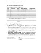
...For information about ... Technology and device width can vary from one row of both DIMM channels are used between channels, the slowest memory timing will be equal. Memory Configuration examples Refer to : http://support.intel.com/support/motherboards/desktop/sb/CS025414.htm 1.5.1 Memory Configurations The 3rd generation Intel Core processor family and 2nd generation Intel Core processor family processors support the following types of memory organization: • Dual channel (Interleaved) mode. Supported Memory Configurations DIMM Capacity Configuration (Note) SDRAM Density...
...For information about ... Technology and device width can vary from one row of both DIMM channels are used between channels, the slowest memory timing will be equal. Memory Configuration examples Refer to : http://support.intel.com/support/motherboards/desktop/sb/CS025414.htm 1.5.1 Memory Configurations The 3rd generation Intel Core processor family and 2nd generation Intel Core processor family processors support the following types of memory organization: • Dual channel (Interleaved) mode. Supported Memory Configurations DIMM Capacity Configuration (Note) SDRAM Density...
Technical Product Specification
Page 20
... keyboard/mouse interfaces on the back panel The location of the SATA connectors Refer to the cable. Use a shielded cable that have an unshielded cable attached to a USB port may not meet FCC Class B requirements, even if no device is the preferred mode for full-speed devices. The SATA controller can operate in both legacy and native modes. Intel Desktop Board DH61HO Technical Product Specification 1.7 USB The board supports up event interface • PCI bus power management support The BIOS Setup program provides configuration options...
... keyboard/mouse interfaces on the back panel The location of the SATA connectors Refer to the cable. Use a shielded cable that have an unshielded cable attached to a USB port may not meet FCC Class B requirements, even if no device is the preferred mode for full-speed devices. The SATA controller can operate in both legacy and native modes. Intel Desktop Board DH61HO Technical Product Specification 1.7 USB The board supports up event interface • PCI bus power management support The BIOS Setup program provides configuration options...

Technical Product Specification
Page 23
.../s) • Intel H61 Express Chipset • RJ-45 LAN connector with integrated status LEDs Additional features of the LAN subsystem include: • CSMA/CD protocol engine • LAN connect interface between the Integrated LAN Controller and the Physical Layer (PHY): PCI Express-based interface for active state operation (S0) state SMBUS for IPv4 and IPv6) • Full device driver compatibility 1.11.2 LAN Subsystem Software LAN software and drivers are...
.../s) • Intel H61 Express Chipset • RJ-45 LAN connector with integrated status LEDs Additional features of the LAN subsystem include: • CSMA/CD protocol engine • LAN connect interface between the Integrated LAN Controller and the Physical Layer (PHY): PCI Express-based interface for active state operation (S0) state SMBUS for IPv4 and IPv6) • Full device driver compatibility 1.11.2 LAN Subsystem Software LAN software and drivers are...
Technical Product Specification
Page 28
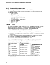
...; Software support through Advanced Configuration and Power Interface (ACPI) • Hardware support: Power connector Fan headers LAN wake capabilities Instantly Available PC technology Wake from USB PCI Express WAKE# signal support Wake from serial port Wake from PS/2 Wake from S5 1.15.1 ACPI ACPI gives the operating system direct control over the power management and Plug and Play functions of ACPI with an ACPI-aware operating system. Intel Desktop Board DH61HO Technical Product Specification 1.15 Power...
...; Software support through Advanced Configuration and Power Interface (ACPI) • Hardware support: Power connector Fan headers LAN wake capabilities Instantly Available PC technology Wake from USB PCI Express WAKE# signal support Wake from serial port Wake from PS/2 Wake from S5 1.15.1 ACPI ACPI gives the operating system direct control over the power management and Plug and Play functions of ACPI with an ACPI-aware operating system. Intel Desktop Board DH61HO Technical Product Specification 1.15 Power...

Technical Product Specification
Page 33
... panel power LED will automatically wake from the S3 state. The board supports the PCI Bus Power Management Interface Specification. NOTE Wake from USB requires the use of providing adequate +5 V standby current. The use of a USB peripheral that will wake the computer is the alt-PrtScrn key combination on the keyboard. 1.15.2.9 Wake from S5 When the RTC Date and Time is set in the BIOS, the computer will behave as configured...
... panel power LED will automatically wake from the S3 state. The board supports the PCI Bus Power Management Interface Specification. NOTE Wake from USB requires the use of providing adequate +5 V standby current. The use of a USB peripheral that will wake the computer is the alt-PrtScrn key combination on the keyboard. 1.15.2.9 Wake from S5 When the RTC Date and Time is set in the BIOS, the computer will behave as configured...
Technical Product Specification
Page 46
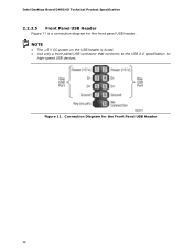
Figure 11. Connection Diagram for high-speed USB devices. NOTE • The +5 V DC power on the USB header is a connection diagram for the front panel USB header. Intel Desktop Board DH61HO Technical Product Specification 2.2.2.5 Front Panel USB Header Figure 11 is fused. • Use only a front panel USB connector that conforms to the USB 2.0 specification for the Front Panel USB Header 46
Figure 11. Connection Diagram for high-speed USB devices. NOTE • The +5 V DC power on the USB header is a connection diagram for the front panel USB header. Intel Desktop Board DH61HO Technical Product Specification 2.2.2.5 Front Panel USB Header Figure 11 is fused. • Use only a front panel USB connector that conforms to the USB 2.0 specification for the Front Panel USB Header 46

Technical Product Specification
Page 47
... Jumper Settings Function/Mode Normal Configure Jumper Setting 1-2 2-3 Configuration The BIOS uses current configuration information and passwords for the three modes: normal, configure, and recovery. Location of the jumper block. Figure 12 shows the location of the Jumper Block Table 22. Press F9 (restore defaults) while in Configure mode to restore the BIOS/CMOS settings to clear the BIOS/CMOS settings. Recovery None The BIOS attempts to recover the BIOS configuration. Table 22 describes the jumper settings for booting. A recovery CD or USB flash drive is displayed...
... Jumper Settings Function/Mode Normal Configure Jumper Setting 1-2 2-3 Configuration The BIOS uses current configuration information and passwords for the three modes: normal, configure, and recovery. Location of the jumper block. Figure 12 shows the location of the Jumper Block Table 22. Press F9 (restore defaults) while in Configure mode to restore the BIOS/CMOS settings to clear the BIOS/CMOS settings. Recovery None The BIOS attempts to recover the BIOS configuration. Table 22 describes the jumper settings for booting. A recovery CD or USB flash drive is displayed...

Technical Product Specification
Page 55
... system boot begins. The SPI Flash contains the BIOS Setup program, POST, LAN EEPROM information, Plug and Play support, and other firmware. The BIOS Setup program can be used to put the board in a 32 Mbit (8.192 KB) Serial Peripheral Interface Flash Memory (SPI Flash) device which can be updated using a set of BIOS and a revision code. 3 Overview of BIOS Features 3.1 Introduction The board uses an Intel BIOS that is shown below. The BIOS displays a message during POST identifying the type of utilities...
... system boot begins. The SPI Flash contains the BIOS Setup program, POST, LAN EEPROM information, Plug and Play support, and other firmware. The BIOS Setup program can be used to put the board in a 32 Mbit (8.192 KB) Serial Peripheral Interface Flash Memory (SPI Flash) device which can be updated using a set of BIOS and a revision code. 3 Overview of BIOS Features 3.1 Introduction The board uses an Intel BIOS that is shown below. The BIOS displays a message during POST identifying the type of utilities...

Technical Product Specification
Page 56
...Intel Desktop Board DH61HO Technical Product Specification Table 27 lists the BIOS Setup program menu features. tion Performance Configures advanced features available through the chipset Configures memory, bus and processor overrides Security Sets passwords and security features Power Configures power management features and power supply controls Boot Selects boot options Exit Saves or discards changes to Setup program options Table 28 lists the function keys available for the current menu Save the current values and exits the BIOS Setup program Exits the menu 56 BIOS...
...Intel Desktop Board DH61HO Technical Product Specification Table 27 lists the BIOS Setup program menu features. tion Performance Configures advanced features available through the chipset Configures memory, bus and processor overrides Security Sets passwords and security features Power Configures power management features and power supply controls Boot Selects boot options Exit Saves or discards changes to Setup program options Table 28 lists the function keys available for the current menu Save the current values and exits the BIOS Setup program Exits the menu 56 BIOS...

Technical Product Specification
Page 57
... system types, capabilities, operational status, and installation dates for accessing this support, an SMBIOS service-level application running on a non-Plug and Play operating system can be found in the BIOS under the Additional Information header under the Main BIOS page. 3.3 Legacy USB Support Legacy USB support enables USB devices to be used to configure the operating system. (Keyboards and mice are not recognized during this period if Legacy USB support was set to Enabled. Legacy USB support is disabled. 2. POST completes...
... system types, capabilities, operational status, and installation dates for accessing this support, an SMBIOS service-level application running on a non-Plug and Play operating system can be found in the BIOS under the Additional Information header under the Main BIOS page. 3.3 Legacy USB Support Legacy USB support enables USB devices to be used to configure the operating system. (Keyboards and mice are not recognized during this period if Legacy USB support was set to Enabled. Legacy USB support is disabled. 2. POST completes...

Technical Product Specification
Page 60
... first boot device, the hard drive second, removable drive third, and the network fourth. 3.6.1 Optical Drive Boot Booting from a hard drive, optical drive, removable drive, or the network. Boot Device Menu Options Boot Device Menu Function Keys or Description Selects a default boot device Exits the menu, and boots from the onboard LAN or a network add-in priority order. The default setting is invoked even if the following devices are defined in card with a remote boot ROM installed. Intel Desktop Board DH61HO Technical Product Specification 3.6 Boot Options In the BIOS Setup...
... first boot device, the hard drive second, removable drive third, and the network fourth. 3.6.1 Optical Drive Boot Booting from a hard drive, optical drive, removable drive, or the network. Boot Device Menu Options Boot Device Menu Function Keys or Description Selects a default boot device Exits the menu, and boots from the onboard LAN or a network add-in priority order. The default setting is invoked even if the following devices are defined in card with a remote boot ROM installed. Intel Desktop Board DH61HO Technical Product Specification 3.6 Boot Options In the BIOS Setup...
Technical Product Specification
Page 62
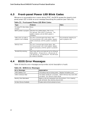
... boot. Front-panel Power LED Blink Codes Type Pattern F2 Setup/F10 Boot Menu None Prompt BIOS update in graphics card installed) On-off . The CMOS checksum is complete. The pattern repeats until the BIOS update is incorrect. Intel Desktop Board DH61HO Technical Product Specification 4.3 Front-panel Power LED Blink Codes Whenever a recoverable error occurs during POST, the BIOS causes the board's front panel power LED to boot. 62 This will be losing power. BIOS Error Messages Error Message CMOS Battery Low CMOS Checksum Bad Memory Size Decreased No Boot Device Available...
... boot. Front-panel Power LED Blink Codes Type Pattern F2 Setup/F10 Boot Menu None Prompt BIOS update in graphics card installed) On-off . The CMOS checksum is complete. The pattern repeats until the BIOS update is incorrect. Intel Desktop Board DH61HO Technical Product Specification 4.3 Front-panel Power LED Blink Codes Whenever a recoverable error occurs during POST, the BIOS causes the board's front panel power LED to boot. 62 This will be losing power. BIOS Error Messages Error Message CMOS Battery Low CMOS Checksum Bad Memory Size Decreased No Boot Device Available...

Technical Product Specification
Page 63
... - 0xFF Entering SX states S0 to I /O buses: PCI, USB, ATA, etc. 0x5F is useful for determining the point where an error occurred. Security (SEC) phase PEI phase pre MRC execution MRC memory detection PEI phase post MRC execution Recovery Platform DXE driver CPU Initialization (PEI, DXE, SMM) I /O port 80h. For future use 63 S3, etc. This code is an unrecoverable error. BDS Output devices: All...
... - 0xFF Entering SX states S0 to I /O buses: PCI, USB, ATA, etc. 0x5F is useful for determining the point where an error occurred. Security (SEC) phase PEI phase pre MRC execution MRC memory detection PEI phase post MRC execution Recovery Platform DXE driver CPU Initialization (PEI, DXE, SMM) I /O port 80h. For future use 63 S3, etc. This code is an unrecoverable error. BDS Output devices: All...


