
Technical Product Specification
Page 5
... compliance and battery disposal information Typographical Conventions This section contains information about the Intel Desktop Board DH61BE and its components to provide detailed, technical information about the conventions used in...Intel® Desktop Board DH61BE. CAUTION Cautions are included to important information. v It is intended to the vendors, system integrators, and other engineers and technicians who need this specification. Preface This Technical Product Specification (TPS) specifies the board layout, components, connectors, power and environmental requirements...
... compliance and battery disposal information Typographical Conventions This section contains information about the Intel Desktop Board DH61BE and its components to provide detailed, technical information about the conventions used in...Intel® Desktop Board DH61BE. CAUTION Cautions are included to important information. v It is intended to the vendors, system integrators, and other engineers and technicians who need this specification. Preface This Technical Product Specification (TPS) specifies the board layout, components, connectors, power and environmental requirements...
Technical Product Specification
Page 16
... about ... NOTE This board has specific requirements for the Intel Desktop Board DH61BE Visit this board. 16 Supported processors Refer to: http://processormatch.intel.com CAUTION Use only the processors listed on power supply requirements for the most up-to support the Intel Core i7, Intel Core i5, Intel Core i3, and Intel Pentium processors in the future. Use of...
... about ... NOTE This board has specific requirements for the Intel Desktop Board DH61BE Visit this board. 16 Supported processors Refer to: http://processormatch.intel.com CAUTION Use only the processors listed on power supply requirements for the most up-to support the Intel Core i7, Intel Core i5, Intel Core i3, and Intel Pentium processors in the future. Use of...
Technical Product Specification
Page 31
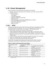
.../Standby (note) (ACPI G1 - Soft off) Note: System can only enter Standby state if power switch action is pressed for ...the system enters this board requires an operating system that enables the operating system to power-off (ACPI G2/G5 - sleeping state) On (ACPI G0 - working state) On (ACPI ...G0 - working state) Less than 15-watt system operation in boards may require an ACPI-aware driver), video displays, and hard disk drives • Methods for a front panel power and sleep mode switch Table 6 lists the system states based on how long the...
.../Standby (note) (ACPI G1 - Soft off) Note: System can only enter Standby state if power switch action is pressed for ...the system enters this board requires an operating system that enables the operating system to power-off (ACPI G2/G5 - sleeping state) On (ACPI G0 - working state) On (ACPI ...G0 - working state) Less than 15-watt system operation in boards may require an ACPI-aware driver), video displays, and hard disk drives • Methods for a front panel power and sleep mode switch Table 6 lists the system states based on how long the...
Technical Product Specification
Page 32
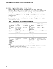
...power D3 - Context saved to the system. No power D3 - Power < 5 W (Note 2) G3 - No power to disk. Service can be performed safely. Table 7 lists the power states supported by applications. working state. Power < 5 W (Note 2) G1 - Intel Desktop Board DH61BE Technical Product Specification 1.16.1.1 System States and Power... standby power consumption of the various system and power states. Notes: 1. Total system power is required. No power to RAM. Devices that are being used in boards and peripherals powered by battery or external source. Power < ...
...power D3 - Context saved to the system. No power D3 - Power < 5 W (Note 2) G3 - No power to disk. Service can be performed safely. Table 7 lists the power states supported by applications. working state. Power < 5 W (Note 2) G1 - Intel Desktop Board DH61BE Technical Product Specification 1.16.1.1 System States and Power... standby power consumption of the various system and power states. Notes: 1. Total system power is required. No power to RAM. Devices that are being used in boards and peripherals powered by battery or external source. Power < ...

Technical Product Specification
Page 33
Product Description 1.16.1.2 Wake-up events from an ACPI state requires an operating system that can wake up the computer... Table 8. Power switch RTC alarm LAN USB PME# signal WAKE# signal Serial port PS/2 Notes: • S4 implies operating system support only. • USB ports are turned ...
Product Description 1.16.1.2 Wake-up events from an ACPI state requires an operating system that can wake up the computer... Table 8. Power switch RTC alarm LAN USB PME# signal WAKE# signal Serial port PS/2 Notes: • S4 implies operating system support only. • USB ports are turned ...
Technical Product Specification
Page 34
... do so can turn off ). Intel Desktop Board DH61BE Technical Product Specification 1.16.2 Hardware Support CAUTION Ensure that provides full ACPI support. 1.16.2.1 Power Connector ATX12V-compliant power supplies can damage the power supply. For information about The location of the main power connector The signal names of standby current required depends on or off the system...
... do so can turn off ). Intel Desktop Board DH61BE Technical Product Specification 1.16.2 Hardware Support CAUTION Ensure that provides full ACPI support. 1.16.2.1 Power Connector ATX12V-compliant power supplies can damage the power supply. For information about The location of the main power connector The signal names of standby current required depends on or off the system...
Technical Product Specification
Page 36
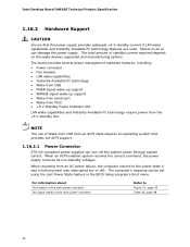
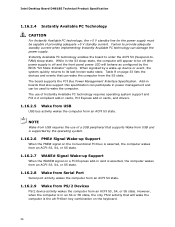
... requires the use of Instantly Available PC technology requires operating system support and PCI 2.2 compliant add-in cards, PCI Express add-in an S4 or S5 state, the only PS/2 activity that will appear to be capable of a USB peripheral that can damage the power ... use of providing adequate +5 V standby current. Intel Desktop Board DH61BE Technical Product Specification 1.16.2.4 Instantly Available PC Technology CAUTION For Instantly Available PC technology, the +5 V standby line for the power supply must be off and the front panel power LED will behave as configured by a wake-up...
... requires the use of Instantly Available PC technology requires operating system support and PCI 2.2 compliant add-in cards, PCI Express add-in an S4 or S5 state, the only PS/2 activity that will appear to be capable of a USB peripheral that can damage the power ... use of providing adequate +5 V standby current. Intel Desktop Board DH61BE Technical Product Specification 1.16.2.4 Instantly Available PC Technology CAUTION For Instantly Available PC technology, the +5 V standby line for the power supply must be off and the front panel power LED will behave as configured by a wake-up...
Technical Product Specification
Page 49
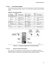
...LED pull-up to an internal storage device. Table 23 lists the signal names of the front panel header. Proper LED function requires a SATA hard drive or optical drive connected to an onboard SATA connector. 49 Technical Reference 2.2.2.4 Front Panel Header This section ... being read from or written to +5 V 3 HDA# Out Hard disk active LED Reset Switch 5 Ground Ground 7 FP_RESET# In Reset switch Power 9 +5 V Power Pin Signal Power LED 2 FP_LED+ 4 FP_LED− On/Off Switch 6 PWR# 8 Ground Not Connected 10 N/C In/ Out Description Out Front panel green LED...
...LED pull-up to an internal storage device. Table 23 lists the signal names of the front panel header. Proper LED function requires a SATA hard drive or optical drive connected to an onboard SATA connector. 49 Technical Reference 2.2.2.4 Front Panel Header This section ... being read from or written to +5 V 3 HDA# Out Hard disk active LED Reset Switch 5 Ground Ground 7 FP_RESET# In Reset switch Power 9 +5 V Power Pin Signal Power LED 2 FP_LED+ 4 FP_LED− On/Off Switch 6 PWR# 8 Ground Not Connected 10 N/C In/ Out Description Out Front panel green LED...
Technical Product Specification
Page 50
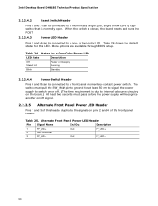
...to a one- More options are available through BIOS setup. The switch must pass before the power supply will recognize another on/off . (The time requirement is normally open. Alternate Front Panel Power LED Header Pin Signal Name In/Out Description 1 FP_LED+ Out FP_LED+ 2 Not connected 3...shows the default states for at least 50 ms to signal the power supply to switch on or off signal. 2.2.2.5 Alternate Front Panel Power LED Header Pins 1 and 3 of the front panel header. Intel Desktop Board DH61BE Technical Product Specification 2.2.2.4.2 Reset Switch Header Pins 5 and 7 can...
...to a one- More options are available through BIOS setup. The switch must pass before the power supply will recognize another on/off . (The time requirement is normally open. Alternate Front Panel Power LED Header Pin Signal Name In/Out Description 1 FP_LED+ Out FP_LED+ 2 Not connected 3...shows the default states for at least 50 ms to signal the power supply to switch on or off signal. 2.2.2.5 Alternate Front Panel Power LED Header Pins 1 and 3 of the front panel header. Intel Desktop Board DH61BE Technical Product Specification 2.2.2.4.2 Reset Switch Header Pins 5 and 7 can...
Technical Product Specification
Page 51
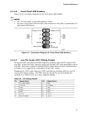
NOTE • The +5 V DC power on the USB headers is a connection diagram for high-speed USB devices. Displaying the POST codes requires a POST card that conforms to I/O port 80h. Table 26. The POST card can interface with the Low Pin Count (LPC) Debug header. LPC Debug Header ...
NOTE • The +5 V DC power on the USB headers is a connection diagram for high-speed USB devices. Displaying the POST codes requires a POST card that conforms to I/O port 80h. Table 26. The POST card can interface with the Low Pin Count (LPC) Debug header. LPC Debug Header ...
Technical Product Specification
Page 56
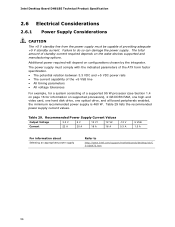
Intel Desktop Board DH61BE Technical Product Specification 2.6 Electrical Considerations 2.6.1 Power Supply Considerations CAUTION The +5 V standby line from the power supply must comply with the indicated parameters of the ATX form factor specification. • The potential relation between 3.3 VDC and +5 VDC power rails...://www.intel.com/support/motherboards/desktop/sb/C S-026472.htm 56 The total amount of standby current required depends on configurations chosen by the integrator. Table 29 lists the recommended power supply current values. Table 29. Additional power required will ...
Intel Desktop Board DH61BE Technical Product Specification 2.6 Electrical Considerations 2.6.1 Power Supply Considerations CAUTION The +5 V standby line from the power supply must comply with the indicated parameters of the ATX form factor specification. • The potential relation between 3.3 VDC and +5 VDC power rails...://www.intel.com/support/motherboards/desktop/sb/C S-026472.htm 56 The total amount of standby current required depends on configurations chosen by the integrator. Table 29 lists the recommended power supply current values. Table 29. Additional power required will ...

Technical Product Specification
Page 63
... non-Plug and Play operating system can be used even when the operating system's USB drivers are recognized by the BIOS allowing you apply power to enter and configure the BIOS Setup program and the maintenance menu. 4. By default, Legacy USB support is disabled. 2. The BIOS... such operating systems. Using this information. Legacy USB support operates as event detection and error logging Non-Plug and Play operating systems require an additional interface for managing computers in the BIOS under the Additional Information header under the Main BIOS page. 3.3 Legacy USB Support...
... non-Plug and Play operating system can be used even when the operating system's USB drivers are recognized by the BIOS allowing you apply power to enter and configure the BIOS Setup program and the maintenance menu. 4. By default, Legacy USB support is disabled. 2. The BIOS... such operating systems. Using this information. Legacy USB support operates as event detection and error logging Non-Plug and Play operating systems require an additional interface for managing computers in the BIOS under the Additional Information header under the Main BIOS page. 3.3 Legacy USB Support...
Technical Product Specification
Page 67
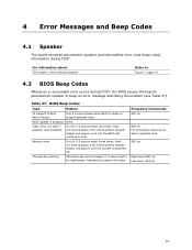
Table 37. Frequency/Comments 932 Hz 932 Hz For processors requiring an add-in graphics card installed) On-off (1.0 second each) two times, then 2.5-second pause (off), entire pattern repeats (beeps and pause) once and the ... error message describing the problem (see Table 37). BIOS Beep Codes Type Pattern F2 Setup/F10 Boot Menu Prompt One 0.5 second beep when BIOS is powered off ), entire pattern repeats (beeps and pause) until the system is ready to accept keyboard input BIOS update in progress None Video error (no add...
Table 37. Frequency/Comments 932 Hz 932 Hz For processors requiring an add-in graphics card installed) On-off (1.0 second each) two times, then 2.5-second pause (off), entire pattern repeats (beeps and pause) once and the ... error message describing the problem (see Table 37). BIOS Beep Codes Type Pattern F2 Setup/F10 Boot Menu Prompt One 0.5 second beep when BIOS is powered off ), entire pattern repeats (beeps and pause) until the system is ready to accept keyboard input BIOS update in progress None Video error (no add...
Technical Product Specification
Page 68
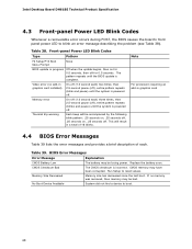
... last boot. Note For processors requiring an add-in graphics card installed) On-off ), entire pattern repeats (blinks and pause) until the system is complete. Table 39. Intel Desktop Board DH61BE Technical Product Specification 4.3 Front-panel Power LED Blink Codes Whenever a recoverable... error occurs during POST, the BIOS causes the board's front panel power LED to reset values. The pattern repeats until ...
... last boot. Note For processors requiring an add-in graphics card installed) On-off ), entire pattern repeats (blinks and pause) until the system is complete. Table 39. Intel Desktop Board DH61BE Technical Product Specification 4.3 Front-panel Power LED Blink Codes Whenever a recoverable... error occurs during POST, the BIOS causes the board's front panel power LED to reset values. The pattern repeats until ...

Technical Product Specification
Page 82
...Intel Desktop Board DH61BE Technical Product Specification 5.1.5 ENERGY STAR* 5.0, e-Standby, and ErP Compliance The US Department of an efficient power supply: • Energy Star v5.0, category A • EPEAT* • Korea e-Standby • European Union Energy-related Products Directive 2009 (ErP) For information about ENERGY STAR requirements...ustainable-business/sustainableproduct-policy/ecodesign/index_en.htm 82 Intel Desktop Board DH61BE meets the following program requirements in the definition of new requirements. Intel has worked directly with these two governmental agencies ...
...Intel Desktop Board DH61BE Technical Product Specification 5.1.5 ENERGY STAR* 5.0, e-Standby, and ErP Compliance The US Department of an efficient power supply: • Energy Star v5.0, category A • EPEAT* • Korea e-Standby • European Union Energy-related Products Directive 2009 (ErP) For information about ENERGY STAR requirements...ustainable-business/sustainableproduct-policy/ecodesign/index_en.htm 82 Intel Desktop Board DH61BE meets the following program requirements in the definition of new requirements. Intel has worked directly with these two governmental agencies ...
English Product Guide
Page 5
...PCI Express Auto Configuration 20 BIOS Security Passwords 21 Intel Manageability Technology 21 Intel® MEBX Reset Header 21 Trusted Platform Module (TPM) Support 22 Fan Speed Control and Hardware Monitoring 23 Power Management 23 Software Support 23 Hardware Support 23 ...Clock Subsystem 27 2 Installing and Replacing Desktop Board Components Before You Begin 29 Installation Precautions 30 Prevent Power Supply Overload 30 Observe Safety and Regulatory Requirements 30 Installing the I/O Shield 31 Installing and Removing the Desktop Board 32 Installing and Removing a Processor...
...PCI Express Auto Configuration 20 BIOS Security Passwords 21 Intel Manageability Technology 21 Intel® MEBX Reset Header 21 Trusted Platform Module (TPM) Support 22 Fan Speed Control and Hardware Monitoring 23 Power Management 23 Software Support 23 Hardware Support 23 ...Clock Subsystem 27 2 Installing and Replacing Desktop Board Components Before You Begin 29 Installation Precautions 30 Prevent Power Supply Overload 30 Observe Safety and Regulatory Requirements 30 Installing the I/O Shield 31 Installing and Removing the Desktop Board 32 Installing and Removing a Processor...
English Product Guide
Page 23
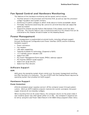
...and Hardware Monitoring The features of the hardware monitoring and fan speed control include: • Thermal sensors in the processor and the Intel PCH, as well as needed • Support for all non-standby voltages. The security feature uses a mechanical switch on or off the computer... from PS/2 devices Software Support ACPI ACPI gives the operating system direct control over the power management and Plug and Play functions of a computer. The use of ACPI with the Desktop Board requires an operating system that detects if the chassis cover has been removed. When an ACPI-enabled...
...and Hardware Monitoring The features of the hardware monitoring and fan speed control include: • Thermal sensors in the processor and the Intel PCH, as well as needed • Support for all non-standby voltages. The security feature uses a mechanical switch on or off the computer... from PS/2 devices Software Support ACPI ACPI gives the operating system direct control over the power management and Plug and Play functions of a computer. The use of ACPI with the Desktop Board requires an operating system that detects if the chassis cover has been removed. When an ACPI-enabled...

English Product Guide
Page 25
... system support and PCI 2.2 compliant add-in cards, PCI Express add-in Figure 4, is lit when there is standby power still present on standby current requirements for the Desktop Board, refer to the Technical Product Specification at the memory module sockets and the PCI connector. Desktop Board ... to the board. Failure to do so could damage the board and any devices connected to be off and the standby power indicator is still present at http://www.intel.com/support/motherboards/desktop/. 25 The Desktop Board's standby power indicator LED, shown in cards, and drivers. +5 V Standby...
... system support and PCI 2.2 compliant add-in cards, PCI Express add-in Figure 4, is lit when there is standby power still present on standby current requirements for the Desktop Board, refer to the Technical Product Specification at the memory module sockets and the PCI connector. Desktop Board ... to the board. Failure to do so could damage the board and any devices connected to be off and the standby power indicator is still present at http://www.intel.com/support/motherboards/desktop/. 25 The Desktop Board's standby power indicator LED, shown in cards, and drivers. +5 V Standby...
English Product Guide
Page 26
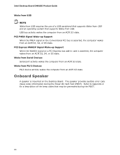
.... 26 Refer to Appendix A for a description of a USB peripheral that supports Wake from USB and an operating system that may be generated during the Power-On Self-Test (POST). USB bus activity wakes the computer from an ACPI S3 state. Onboard Speaker A speaker is asserted, the computer wakes from USB...Express bus add-in card is mounted on the Conventional PCI bus is asserted, the computer wakes from an ACPI S3 state. Intel Desktop Board DH61BE Product Guide Wake from USB NOTE Wake from USB requires the use of the beep codes that supports Wake from an ACPI S3, S4, or S5 state.
.... 26 Refer to Appendix A for a description of a USB peripheral that supports Wake from USB and an operating system that may be generated during the Power-On Self-Test (POST). USB bus activity wakes the computer from an ACPI S3 state. Onboard Speaker A speaker is asserted, the computer wakes from USB...Express bus add-in card is mounted on the Conventional PCI bus is asserted, the computer wakes from an ACPI S3 state. Intel Desktop Board DH61BE Product Guide Wake from USB NOTE Wake from USB requires the use of the beep codes that supports Wake from an ACPI S3, S4, or S5 state.
English Product Guide
Page 29
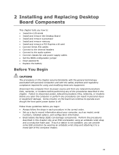
... procedures in this chapter assume familiarity with the general terminology associated with personal computers and with the safety practices and regulatory compliance required for using an antistatic wrist strap and a conductive foam pad. Perform the procedures described in this chapter. Some circuitry on ... you begin: • Always follow the steps in each procedure in the correct order. • Set up a log to disconnect power, telecommunications links, networks, or modems before you open the computer or perform any of the computer chassis. 29 Failure to record information ...
... procedures in this chapter assume familiarity with the general terminology associated with personal computers and with the safety practices and regulatory compliance required for using an antistatic wrist strap and a conductive foam pad. Perform the procedures described in this chapter. Some circuitry on ... you begin: • Always follow the steps in each procedure in the correct order. • Set up a log to disconnect power, telecommunications links, networks, or modems before you open the computer or perform any of the computer chassis. 29 Failure to record information ...

