

Product Specification
Page 5
...11 1.1.3 Block Diagram 13 1.2 Legacy Considerations 14 1.3 Online Support 14 1.4 Processor 14 1.5 System Memory 15 1.5.1 Memory Configurations 16 1.6 Intel® G41 Express Chipset 18 1.6.1 Intel® G41 Graphics Subsystem 18 1.6.2 USB 20 1.6.3 Serial ATA Interfaces 21 1.7 Parallel ATA IDE Controller 22 1.8 Real-Time Clock Subsystem...Compliance 37 2 Technical Reference 2.1 Memory Map 39 2.1.1 Addressable Memory 39 2.2 Connectors and Headers 42 2.2.1 Back Panel Connectors 43 2.2.2 Component-side Connectors and Headers 44 2.3 Jumper Block 53 2.4 Mechanical Considerations 55 v
...11 1.1.3 Block Diagram 13 1.2 Legacy Considerations 14 1.3 Online Support 14 1.4 Processor 14 1.5 System Memory 15 1.5.1 Memory Configurations 16 1.6 Intel® G41 Express Chipset 18 1.6.1 Intel® G41 Graphics Subsystem 18 1.6.2 USB 20 1.6.3 Serial ATA Interfaces 21 1.7 Parallel ATA IDE Controller 22 1.8 Real-Time Clock Subsystem...Compliance 37 2 Technical Reference 2.1 Memory Map 39 2.1.1 Addressable Memory 39 2.2 Connectors and Headers 42 2.2.1 Back Panel Connectors 43 2.2.2 Component-side Connectors and Headers 44 2.3 Jumper Block 53 2.4 Mechanical Considerations 55 v

Product Specification
Page 6
Intel Desktop Board DG41TX Technical Product Specification 2.4.1 Form Factor 55 2.5 Electrical Considerations 56 2.5.1 Power Supply Considerations 56 2.5.2 Fan Header Current Capability 57 2.5.3 Add-in Board Considerations 57 2.6 Thermal...and Configuration 68 3.9.2 BIOS Boot Optimizations 68 3.10 BIOS Security Features 69 4 Error Messages and Beep Codes 4.1 Speaker 71 4.2 BIOS Beep Codes 71 4.3 Front-panel Power LED Blink Codes 72 4.4 BIOS Error Messages 72 4.5 Port 80h POST Codes 73 5 Regulatory Compliance and Battery Disposal Information 5.1 Regulatory Compliance 79 5.1.1 Safety ...
Intel Desktop Board DG41TX Technical Product Specification 2.4.1 Form Factor 55 2.5 Electrical Considerations 56 2.5.1 Power Supply Considerations 56 2.5.2 Fan Header Current Capability 57 2.5.3 Add-in Board Considerations 57 2.6 Thermal...and Configuration 68 3.9.2 BIOS Boot Optimizations 68 3.10 BIOS Security Features 69 4 Error Messages and Beep Codes 4.1 Speaker 71 4.2 BIOS Beep Codes 71 4.3 Front-panel Power LED Blink Codes 72 4.4 BIOS Error Messages 72 4.5 Port 80h POST Codes 73 5 Regulatory Compliance and Battery Disposal Information 5.1 Regulatory Compliance 79 5.1.1 Safety ...

Product Specification
Page 7
... 25 5. Audio Jack Retasking Support 24 5. Effects of the Standby Power Indicator LED 36 8. Intel HD Audio Link Header 47 19. Front Panel Header 50 23. BIOS Setup Configuration Jumper Settings 54 27. Front Panel Audio Header for Front Panel Header 50 12. Processor Core Power Connector 49 21. Memory Channel Configuration and DIMM...
... 25 5. Audio Jack Retasking Support 24 5. Effects of the Standby Power Indicator LED 36 8. Intel HD Audio Link Header 47 19. Front Panel Header 50 23. BIOS Setup Configuration Jumper Settings 54 27. Front Panel Audio Header for Front Panel Header 50 12. Processor Core Power Connector 49 21. Memory Channel Configuration and DIMM...
Product Specification
Page 8
...-panel Power LED Blink Codes 72 38. Typical Port 80h POST Sequence 77 42. Boot Device Menu Options 67 35. Lead-Free Board Markings 84 44. Product Certification Markings 86 viii Port 80h POST Code Ranges 73 40. Safety Standards 79 43. Intel Desktop Board DG41TX Technical Product Specification 29. Intel Desktop Board DG41TX Environmental...
...-panel Power LED Blink Codes 72 38. Typical Port 80h POST Sequence 77 42. Boot Device Menu Options 67 35. Lead-Free Board Markings 84 44. Product Certification Markings 86 viii Port 80h POST Code Ranges 73 40. Safety Standards 79 43. Intel Desktop Board DG41TX Technical Product Specification 29. Intel Desktop Board DG41TX Environmental...
Product Specification
Page 10
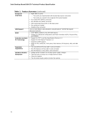
Intel Desktop Board DG41TX Technical Product Specification Table 1. Feature Summary (continued) Peripheral Interfaces • Eight USB 2.0 ports: ― Four ports are implemented with stacked back panel connectors ― Four ports are routed to two separate front panel headers • Four Serial ATA (SATA) ...Technology Expansion Capabilities Hardware Monitor Subsystem 10/100/1000 Mbits/s LAN subsystem using Broadcom* BCM57788 Gigabit Ethernet Controller • Intel® BIOS (resident in the SPI Flash device) • Support for Advanced Configuration and Power Interface (ACPI), ...
Intel Desktop Board DG41TX Technical Product Specification Table 1. Feature Summary (continued) Peripheral Interfaces • Eight USB 2.0 ports: ― Four ports are implemented with stacked back panel connectors ― Four ports are routed to two separate front panel headers • Four Serial ATA (SATA) ...Technology Expansion Capabilities Hardware Monitor Subsystem 10/100/1000 Mbits/s LAN subsystem using Broadcom* BCM57788 Gigabit Ethernet Controller • Intel® BIOS (resident in the SPI Flash device) • Support for Advanced Configuration and Power Interface (ACPI), ...
Product Specification
Page 14
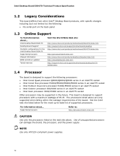
... Product Specification 1.2 Legacy Considerations This board differs from other Intel® Desktop Board products, with a maximum wattage of 95 W. Intel Desktop Board DG41TX Desktop Board Support Available configurations for the most up-to : http://processormatch.intel.com CAUTION Use only the processors listed on the back panel 1.3 Online Support To find information about ... For information...
... Product Specification 1.2 Legacy Considerations This board differs from other Intel® Desktop Board products, with a maximum wattage of 95 W. Intel Desktop Board DG41TX Desktop Board Support Available configurations for the most up-to : http://processormatch.intel.com CAUTION Use only the processors listed on the back panel 1.3 Online Support To find information about ... For information...
Product Specification
Page 20
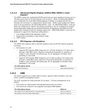
... mode. ⎯ Supports PCI Express GEN2 frequency of 16 GB/s when operating in 5.0 Gb/s each direction (500 MB/s total). Intel Desktop Board DG41TX Technical Product Specification 1.6.1.5 Advanced Digital Display (ADD2/MEC/ADD2+) Card Support The GMCH routes two multiplexed SDVO ports that are routed to two... enabled and the PCI Express x16 connector is as an extended desktop configuration with different color depths and resolutions with stacked back panel connectors • Four ports are each capable of driving up to support simultaneous display or can be accessed by the ADD2/...
... mode. ⎯ Supports PCI Express GEN2 frequency of 16 GB/s when operating in 5.0 Gb/s each direction (500 MB/s total). Intel Desktop Board DG41TX Technical Product Specification 1.6.1.5 Advanced Digital Display (ADD2/MEC/ADD2+) Card Support The GMCH routes two multiplexed SDVO ports that are routed to two... enabled and the PCI Express x16 connector is as an extended desktop configuration with different color depths and resolutions with stacked back panel connectors • Four ports are each capable of driving up to support simultaneous display or can be accessed by the ADD2/...

Product Specification
Page 23
... port supports data transfers at 25 ºC with serialized IRQ support for PCI systems • PS/2-style keyboard/mouse interfaces • One parallel port back panel connector • Intelligent power management, including a programmable wake-up to Figure 10, page 44 Table 12, page 46 23 The clock is not plugged into...
... port supports data transfers at 25 ºC with serialized IRQ support for PCI systems • PS/2-style keyboard/mouse interfaces • One parallel port back panel connector • Intelligent power management, including a programmable wake-up to Figure 10, page 44 Table 12, page 46 23 The clock is not plugged into...
Product Specification
Page 24
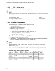
... Microphone Headphones Front Speaker Line In FP Green Ctrl Panel Default FP Pink Default Rear Blue Default Rear Green Ctrl panel Default Rear Pink Default Rear Surround Center/ Sub Ctrl Panel Ctrl Panel 24 Table 4. NOTE Power to obtain the Microsoft Windows Vista logo. Intel Desktop Board DG41TX Technical Product Specification 1.9.2 PS/2 Interfaces The PS/2 connectors...
... Microphone Headphones Front Speaker Line In FP Green Ctrl Panel Default FP Pink Default Rear Blue Default Rear Green Ctrl panel Default Rear Pink Default Rear Surround Center/ Sub Ctrl Panel Ctrl Panel 24 Table 4. NOTE Power to obtain the Microsoft Windows Vista logo. Intel Desktop Board DG41TX Technical Product Specification 1.9.2 PS/2 Interfaces The PS/2 connectors...

Product Specification
Page 25
..., page 47 Section 2.2.1, page 43 25 Back Panel Audio Connector Options NOTE The back panel audio line out connector is supported for the front panel. Poor audio quality occurs if passive (non-amplified) speakers are available from Intel's World Wide Web site. The audio headers and... connectors are shown in Figure 4. The front panel audio header provides mic in Figure 4. Product Description 1.10.1 Audio Subsystem Software Audio software and drivers are...
..., page 47 Section 2.2.1, page 43 25 Back Panel Audio Connector Options NOTE The back panel audio line out connector is supported for the front panel. Poor audio quality occurs if passive (non-amplified) speakers are available from Intel's World Wide Web site. The audio headers and... connectors are shown in Figure 4. The front panel audio header provides mic in Figure 4. Product Description 1.10.1 Audio Subsystem Software Audio software and drivers are...

Product Specification
Page 30
...a computer. Soft off (ACPI G2/G5 - working state) On (ACPI G0 - sleeping state) ...and the power switch is pressed for a front panel power and sleep mode switch Table 6 lists the system states based on how long the power switch is configured with the board requires an operating...gives the operating system direct control over the power management and Plug and Play functions of ACPI with an ACPI-aware operating system. Intel Desktop Board DG41TX Technical Product Specification 1.13 Power Management Power management is in the power-on/standby sleeping state • A Soft-off feature ...
...a computer. Soft off (ACPI G2/G5 - working state) On (ACPI G0 - sleeping state) ...and the power switch is pressed for a front panel power and sleep mode switch Table 6 lists the system states based on how long the power switch is configured with the board requires an operating...gives the operating system direct control over the power management and Plug and Play functions of ACPI with an ACPI-aware operating system. Intel Desktop Board DG41TX Technical Product Specification 1.13 Power Management Power management is in the power-on/standby sleeping state • A Soft-off feature ...

Product Specification
Page 35
... (Suspend-toRAM) sleep-state. While in the S3 sleep-state, the computer will appear to be off (the power supply is off, and the front panel LED is amber if dual colored, or off if single colored.) When signaled by a wake-up Support When the WAKE# signal on the PCI Express...
... (Suspend-toRAM) sleep-state. While in the S3 sleep-state, the computer will appear to be off (the power supply is off, and the front panel LED is amber if dual colored, or off if single colored.) When signaled by a wake-up Support When the WAKE# signal on the PCI Express...

Product Specification
Page 42
...external to the computer's chassis. A fault in the load presented by the external devices could cause damage to the board. Intel Desktop Board DG41TX Technical Product Specification 2.2 Connectors and Headers CAUTION Only the following connectors and headers have an unshielded cable attached to a USB... damage to the computer, the power cable, and the external devices themselves. Use shielded cable that have overcurrent protection: Back panel and front panel USB, VGA, and PS/2. Furthermore, improper connection of USB header signal wire connectors may not meet FCC Class B requirements,...
...external to the computer's chassis. A fault in the load presented by the external devices could cause damage to the board. Intel Desktop Board DG41TX Technical Product Specification 2.2 Connectors and Headers CAUTION Only the following connectors and headers have an unshielded cable attached to a USB... damage to the computer, the power cable, and the external devices themselves. Use shielded cable that have overcurrent protection: Back panel and front panel USB, VGA, and PS/2. Furthermore, improper connection of USB header signal wire connectors may not meet FCC Class B requirements,...

Product Specification
Page 43
Back Panel Connectors 43 Item A B C D E F G H I J K Description PS/2 keyboard/mouse port PS/2 keyboard/mouse port VGA output Parallel port DVI-D output USB ports (2) LAN USB ports (2) Line in Line out Mic in Figure 9. Technical Reference 2.2.1 Back Panel Connectors Figure 9 shows the locations of the back panel connectors.
Back Panel Connectors 43 Item A B C D E F G H I J K Description PS/2 keyboard/mouse port PS/2 keyboard/mouse port VGA output Parallel port DVI-D output USB ports (2) LAN USB ports (2) Line in Line out Mic in Figure 9. Technical Reference 2.2.1 Back Panel Connectors Figure 9 shows the locations of the back panel connectors.

Product Specification
Page 45
Table 10. Component-side Connectors and Headers Shown in Figure 10 Item/callout from Figure 1 Description A Front panel audio header B Conventional PCI bus add-in card connector C Conventional PCI bus add-in card connector D PCI... Parallel ATA IDE connector L Main power connector (2 x 12) M Serial ATA connectors (4) N Front chassis fan header O Chassis intrusion header P Front panel USB header Q Front panel USB header R Front panel header S Alternate front panel power LED header T Serial port header U Intel High Definition Audio Link header V S/PDIF header 45
Table 10. Component-side Connectors and Headers Shown in Figure 10 Item/callout from Figure 1 Description A Front panel audio header B Conventional PCI bus add-in card connector C Conventional PCI bus add-in card connector D PCI... Parallel ATA IDE connector L Main power connector (2 x 12) M Serial ATA connectors (4) N Front chassis fan header O Chassis intrusion header P Front panel USB header Q Front panel USB header R Front panel header S Alternate front panel power LED header T Serial port header U Intel High Definition Audio Link header V S/PDIF header 45

Product Specification
Page 47
... 1 MIC 3 MIC_BIAS 5 FP_OUT_R 7 N/A 2 AUD_GND 4 AUD_GND 6 FP_RETURN_R 8 Key (no pin) 10 [Port 2] SENSE_RETURN Table 17. Front Panel Audio Header for Intel HD Audio Pin Signal Name Pin Signal Name 1 [Port 1] Left channel 3 [Port 1] Right channel 5 [Port 2] Right channel 7 SENSE_SEND (Jack...FP_OUT_L 10 FP_RETURN_L Table 18. S/PDIF Header Pin Signal Name 1 Ground 2 S/PDIF out 3 Key (no pin) 3.3 V DUAL Ground Table 19. Intel HD Audio Link Header Pin Signal Name Pin 1 BCLK 2 3 RST# 4 5 SYNC 6 7 SDO 8 9 SDI0 10 11 SDI1 12 13 Not...
... 1 MIC 3 MIC_BIAS 5 FP_OUT_R 7 N/A 2 AUD_GND 4 AUD_GND 6 FP_RETURN_R 8 Key (no pin) 10 [Port 2] SENSE_RETURN Table 17. Front Panel Audio Header for Intel HD Audio Pin Signal Name Pin Signal Name 1 [Port 1] Left channel 3 [Port 1] Right channel 5 [Port 2] Right channel 7 SENSE_SEND (Jack...FP_OUT_L 10 FP_RETURN_L Table 18. S/PDIF Header Pin Signal Name 1 Ground 2 S/PDIF out 3 Key (no pin) 3.3 V DUAL Ground Table 19. Intel HD Audio Link Header Pin Signal Name Pin 1 BCLK 2 3 RST# 4 5 SYNC 6 7 SDO 8 9 SDI0 10 11 SDI1 12 13 Not...

Product Specification
Page 50
... LED 1 HD_PWR Out Hard disk LED pull-up 2 to an onboard Parallel ATA IDE connector 50 Table 22. Intel Desktop Board DG41TX Technical Product Specification 2.2.2.4 Front Panel Header This section describes the functions of the front panel header. Figure 11 is being read from or written to provide a visual indicator that data is a connection...
... LED 1 HD_PWR Out Hard disk LED pull-up 2 to an onboard Parallel ATA IDE connector 50 Table 22. Intel Desktop Board DG41TX Technical Product Specification 2.2.2.4 Front Panel Header This section describes the functions of the front panel header. Figure 11 is being read from or written to provide a visual indicator that data is a connection...

Product Specification
Page 51
...Switch Header Pins 6 and 8 can be connected to a momentary single pole, single throw (SPST) type switch that is due to a front panel momentary-contact power switch. Table 23 shows the possible states for a One-Color Power LED LED State Description Off Steady Green Power off signal. ... the signals on pins 2 and 4 of the front panel header. States for a one - Alternate Front Panel Power LED Header Pin Signal Name 1 HDR_BLNK_GRN 2 Not connected 3 HDR_BLNK_YEL In/Out Out Out Description Front panel green LED Front panel yellow LED 51 When the switch is closed, the board...
...Switch Header Pins 6 and 8 can be connected to a momentary single pole, single throw (SPST) type switch that is due to a front panel momentary-contact power switch. Table 23 shows the possible states for a One-Color Power LED LED State Description Off Steady Green Power off signal. ... the signals on pins 2 and 4 of the front panel header. States for a one - Alternate Front Panel Power LED Header Pin Signal Name 1 HDR_BLNK_GRN 2 Not connected 3 HDR_BLNK_YEL In/Out Out Out Description Front panel green LED Front panel yellow LED 51 When the switch is closed, the board...

Product Specification
Page 52
Use only a front panel USB connector that conforms to the USB 2.0 specification for Front Panel USB Headers 52 Figure 12. NOTES The +5 V DC power on the front panel USB headers is a connection diagram for the front panel USB headers. Connection Diagram for high-speed USB devices. Intel Desktop Board DG41TX Technical Product Specification 2.2.2.6 Front Panel USB Headers Figure 12 is fused.
Use only a front panel USB connector that conforms to the USB 2.0 specification for Front Panel USB Headers 52 Figure 12. NOTES The +5 V DC power on the front panel USB headers is a connection diagram for the front panel USB headers. Connection Diagram for high-speed USB devices. Intel Desktop Board DG41TX Technical Product Specification 2.2.2.6 Front Panel USB Headers Figure 12 is fused.

Product Specification
Page 72
...recoverable error occurs during POST, the BIOS causes the board's front panel power LED to blink an error message describing the problem (see Table 37). Intel Desktop Board DG41TX Technical Product Specification 4.3 Front-panel Power LED Blink Codes Whenever a recoverable error occurs during POST, the.... Table 38 lists the error messages and provides a brief description of each ) two times, then 3.0 second pause (off . Front-panel Power LED Blink Codes Type Pattern Note Processor initialization complete On when the system powers up , then off ), entire pattern repeats (blinks and...
...recoverable error occurs during POST, the BIOS causes the board's front panel power LED to blink an error message describing the problem (see Table 37). Intel Desktop Board DG41TX Technical Product Specification 4.3 Front-panel Power LED Blink Codes Whenever a recoverable error occurs during POST, the.... Table 38 lists the error messages and provides a brief description of each ) two times, then 3.0 second pause (off . Front-panel Power LED Blink Codes Type Pattern Note Processor initialization complete On when the system powers up , then off ), entire pattern repeats (blinks and...


