Product Guide
Page 5
Contents 1 Desktop Board Features Desktop Board Components 11 Processor ...13 Main Memory...13 Intel® G35 Express Chipset 14 Intel G35 Graphics Subsystem 14 Audio Subsystem 15 Legacy Input/Output (I/O) Controller 16 LAN Subsystem 16 LAN Status Indicators 16...-up Support 23 ENERGY STAR* Qualified 23 Speaker...23 Battery ...23 Real-Time Clock 23 2 Installing and Replacing Desktop Board Components Before You Begin 25 Installation Precautions 26 Prevent Power Supply Overload 26 Observe Safety and Regulatory Requirements 26 Installing the I/O Shield 27 Installing and Removing the...
Contents 1 Desktop Board Features Desktop Board Components 11 Processor ...13 Main Memory...13 Intel® G35 Express Chipset 14 Intel G35 Graphics Subsystem 14 Audio Subsystem 15 Legacy Input/Output (I/O) Controller 16 LAN Subsystem 16 LAN Status Indicators 16...-up Support 23 ENERGY STAR* Qualified 23 Speaker...23 Battery ...23 Real-Time Clock 23 2 Installing and Replacing Desktop Board Components Before You Begin 25 Installation Precautions 26 Prevent Power Supply Overload 26 Observe Safety and Regulatory Requirements 26 Installing the I/O Shield 27 Installing and Removing the...

Product Guide
Page 6
Intel Desktop Board DG35EC Product Guide Installing a Processor Fan Heat Sink 32 Connecting the Processor Fan Heat Sink Cable 33 ... Onboard Audio System 48 Connecting Chassis Fan and Power Supply Cables 49 Chassis Fan Cables 49 Power Supply Cables 50 Setting the BIOS Configuration Jumper 51 Clearing Passwords 52 3 Updating the BIOS Updating the BIOS with the Intel® Express BIOS Update Utility 59 Updating the... Conformity Statement 66 Product Ecology Statements 67 Recycling Considerations 67 Lead-free 2LI/Pb-free 2LI Board 70 Restriction of Hazardous Substances (RoHS 71 vi
Intel Desktop Board DG35EC Product Guide Installing a Processor Fan Heat Sink 32 Connecting the Processor Fan Heat Sink Cable 33 ... Onboard Audio System 48 Connecting Chassis Fan and Power Supply Cables 49 Chassis Fan Cables 49 Power Supply Cables 50 Setting the BIOS Configuration Jumper 51 Clearing Passwords 52 3 Updating the BIOS Updating the BIOS with the Intel® Express BIOS Update Utility 59 Updating the... Conformity Statement 66 Product Ecology Statements 67 Recycling Considerations 67 Lead-free 2LI/Pb-free 2LI Board 70 Restriction of Hazardous Substances (RoHS 71 vi

Product Guide
Page 7
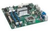
... vii Dual Channel Memory Configuration with Three DIMMs 35 16. Installing a PCI Express x16 Card 39 19. Connecting Power Supply Cables 50 27. Removing the Battery 57 29. Desktop Board DG35EC Components 11 2. Location of the +5 V Standby Power Indicator 22 4. Close the Load Plate 32 12. Removing a PCI Express x16 Card 40 20. Lift the Socket...
... vii Dual Channel Memory Configuration with Three DIMMs 35 16. Installing a PCI Express x16 Card 39 19. Connecting Power Supply Cables 50 27. Removing the Battery 57 29. Desktop Board DG35EC Components 11 2. Location of the +5 V Standby Power Indicator 22 4. Close the Load Plate 32 12. Removing a PCI Express x16 Card 40 20. Lift the Socket...

Product Guide
Page 10
...8226; Voltage sense to detect out of range power supply voltages • Thermal sense to detect out of range temperatures • Three fan headers • Three fan sense inputs to monitor fan speed LAN Support Intel® 82566DC Gigabit (10/100/1000 Mb...; Microsoft Windows XP Professional x64 Edition • Microsoft Windows XP Home For more information about Desktop Board DG35EC, including the Technical Product Specification (TPS), BIOS updates, and device drivers, go to http://support.intel.com/support/motherboards/desktop/. 10 Intel Desktop Board DG35EC Product Guide Table 1.
...8226; Voltage sense to detect out of range power supply voltages • Thermal sense to detect out of range temperatures • Three fan headers • Three fan sense inputs to monitor fan speed LAN Support Intel® 82566DC Gigabit (10/100/1000 Mb...; Microsoft Windows XP Professional x64 Edition • Microsoft Windows XP Home For more information about Desktop Board DG35EC, including the Technical Product Specification (TPS), BIOS updates, and device drivers, go to http://support.intel.com/support/motherboards/desktop/. 10 Intel Desktop Board DG35EC Product Guide Table 1.
Product Guide
Page 13
... the memory controller for Desktop Board DG35EC, http://www.intel.com/go/findCPU Main Memory NOTE To be fully compliant with all applicable Intel ® SDRAM memory specifications, the board should be purchased separately. Desktop Board Features Processor CAUTION Failure to use an appropriate power supply and/or not connecting the 12 V (2 x 2 pin) power connector to the Desktop Board may not function properly...
... the memory controller for Desktop Board DG35EC, http://www.intel.com/go/findCPU Main Memory NOTE To be fully compliant with all applicable Intel ® SDRAM memory specifications, the board should be purchased separately. Desktop Board Features Processor CAUTION Failure to use an appropriate power supply and/or not connecting the 12 V (2 x 2 pin) power connector to the Desktop Board may not function properly...
Product Guide
Page 19
... before the computer is set , you can boot the computer. See Figure 23 for the location of Desktop Board DG35EC enable the board to be connected to detect levels above and below acceptable values • Fan speed controllers and sensors integrated...board has several hardware management features including the following: • Fan speed monitoring and control • Thermal and voltage monitoring • Chassis intrusion detection Hardware Monitoring and Fan Speed Control The features of the hardware monitoring and fan speed control include: • Monitoring of power supply...
... before the computer is set , you can boot the computer. See Figure 23 for the location of Desktop Board DG35EC enable the board to be connected to detect levels above and below acceptable values • Fan speed controllers and sensors integrated...board has several hardware management features including the following: • Fan speed monitoring and control • Thermal and voltage monitoring • Chassis intrusion detection Hardware Monitoring and Fan Speed Control The features of the hardware monitoring and fan speed control include: • Monitoring of power supply...
Product Guide
Page 20
... off the computer power through the Advanced Configuration and Power Interface (ACPI) • Hardware support: ⎯ Power connectors ⎯ Fan headers ⎯ LAN wake capabilities ⎯ Instantly Available PC technology (Suspend to the power state it was in the BIOS Setup program's Boot menu. The Desktop Board has two power connectors. Intel Desktop Board DG35EC Product Guide Power Management Features Power management is...
... off the computer power through the Advanced Configuration and Power Interface (ACPI) • Hardware support: ⎯ Power connectors ⎯ Fan headers ⎯ LAN wake capabilities ⎯ Instantly Available PC technology (Suspend to the power state it was in the BIOS Setup program's Boot menu. The Desktop Board has two power connectors. Intel Desktop Board DG35EC Product Guide Power Management Features Power management is...
Product Guide
Page 21
...state) configuration. If the standby current necessary to support multiple wake events from the PCI and/or USB buses exceeds power supply capacity, the Desktop Board may lose register settings stored in the S3 sleep state, the computer will appear to be used with this feature ...can damage the power supply. The Desktop Board has a 4-pin processor fan header and two 3-pin chassis fan headers. Failure to enter the ACPI S3 (Suspend-toRAM) sleep state. The Desktop Board supports the PCI Bus Power Management Interface Specification. LAN Wake Capabilities CAUTION...
...state) configuration. If the standby current necessary to support multiple wake events from the PCI and/or USB buses exceeds power supply capacity, the Desktop Board may lose register settings stored in the S3 sleep state, the computer will appear to be used with this feature ...can damage the power supply. The Desktop Board has a 4-pin processor fan header and two 3-pin chassis fan headers. Failure to enter the ACPI S3 (Suspend-toRAM) sleep state. The Desktop Board supports the PCI Bus Power Management Interface Specification. LAN Wake Capabilities CAUTION...
Product Guide
Page 25
... front panel power button is not available, you can damage components. 2 Installing and Replacing Desktop Board Components This chapter tells you how to: • Install the I/O shield • Install and remove the Desktop Board • ...Install and remove a processor • Install and remove memory • Install and remove a PCI Express x16 card • Connect the diskette drive cable • Connect the IDE and Serial ATA cables • Connect to the internal headers • Connect to the onboard audio system • Connect chassis fan and power supply...
... front panel power button is not available, you can damage components. 2 Installing and Replacing Desktop Board Components This chapter tells you how to: • Install the I/O shield • Install and remove the Desktop Board • ...Install and remove a processor • Install and remove memory • Install and remove a PCI Express x16 card • Connect the diskette drive cable • Connect the IDE and Serial ATA cables • Connect to the internal headers • Connect to the onboard audio system • Connect chassis fan and power supply...

Product Guide
Page 26
... of all warnings and cautions in this section and the instructions supplied with regional laws and regulations. To avoid injury, be careful of the power supplies output circuits. Prevent Power Supply Overload Do not overload the power supply output. Observe Safety and Regulatory Requirements Read and adhere the instructions...pins on connectors • Sharp pins on printed circuit assemblies • Rough edges and sharp corners on page 65. 26 Intel Desktop Board DG35EC Product Guide Installation Precautions When you to refer computer servicing to qualified technical personnel.
... of all warnings and cautions in this section and the instructions supplied with regional laws and regulations. To avoid injury, be careful of the power supplies output circuits. Prevent Power Supply Overload Do not overload the power supply output. Observe Safety and Regulatory Requirements Read and adhere the instructions...pins on connectors • Sharp pins on printed circuit assemblies • Rough edges and sharp corners on page 65. 26 Intel Desktop Board DG35EC Product Guide Installation Precautions When you to refer computer servicing to qualified technical personnel.
Product Guide
Page 39
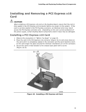
... a PCI Express x16 Card CAUTION When installing a PCI Express x16 card on the Desktop Board, ensure that the card is fully seated in the PCI Express x16 connector before you power on the over-current protection of the power supply, certain Desktop Board components and/or traces may result across the PCI Express connector pins. Depending on...
... a PCI Express x16 Card CAUTION When installing a PCI Express x16 card on the Desktop Board, ensure that the card is fully seated in the PCI Express x16 connector before you power on the over-current protection of the power supply, certain Desktop Board components and/or traces may result across the PCI Express connector pins. Depending on...
Product Guide
Page 49
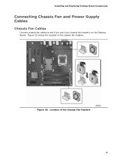
Figure 25. Location of the chassis fan headers. Installing and Replacing Desktop Board Components Connecting Chassis Fan and Power Supply Cables Chassis Fan Cables Connect chassis fan cables to the 3-pin and 4-pin chassis fan headers on the Desktop Board. Figure 25 shows the location of the Chassis Fan Headers 49
Figure 25. Location of the chassis fan headers. Installing and Replacing Desktop Board Components Connecting Chassis Fan and Power Supply Cables Chassis Fan Cables Connect chassis fan cables to the 3-pin and 4-pin chassis fan headers on the Desktop Board. Figure 25 shows the location of the Chassis Fan Headers 49
Product Guide
Page 50
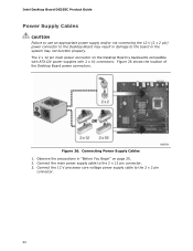
... Begin" on the Desktop Board is backwards compatible with ATX12V power supplies with 2 x 10 connectors. The 2 x 12 pin main power connector on page 25. 2. Connecting Power Supply Cables 1. Intel Desktop Board DG35EC Product Guide Power Supply Cables CAUTION Failure to use an appropriate power supply and/or not connecting the 12 V (2 x 2 pin) power connector to the Desktop Board may not function properly. Connect the main power supply cable to the...
... Begin" on the Desktop Board is backwards compatible with ATX12V power supplies with 2 x 10 connectors. The 2 x 12 pin main power connector on page 25. 2. Connecting Power Supply Cables 1. Intel Desktop Board DG35EC Product Guide Power Supply Cables CAUTION Failure to use an appropriate power supply and/or not connecting the 12 V (2 x 2 pin) power connector to the Desktop Board may not function properly. Connect the main power supply cable to the...

Product Guide
Page 53
Replacing the Battery A coin-cell battery (CR2032) powers the real-time clock and CMOS memory. FORHOLDSREGEL Eksplosionsfare, hvis batteriet erstattes med et batteri af en forkert type. Det kan oppstå eksplosjonsfare hvis ... battery is not plugged into a wall socket, the battery has an estimated life of the battery. Installing and Replacing Desktop Board Components 12. Replace the cover, plug in , the standby current from the power supply extends the life of three years. Batteries should be recycled where possible. La mise au rebut des piles usag...
Replacing the Battery A coin-cell battery (CR2032) powers the real-time clock and CMOS memory. FORHOLDSREGEL Eksplosionsfare, hvis batteriet erstattes med et batteri af en forkert type. Det kan oppstå eksplosjonsfare hvis ... battery is not plugged into a wall socket, the battery has an estimated life of the battery. Installing and Replacing Desktop Board Components 12. Replace the cover, plug in , the standby current from the power supply extends the life of three years. Batteries should be recycled where possible. La mise au rebut des piles usag...

Product Guide
Page 75
... Compliance Korean Class B statement translation: This is certified to the following when reading the installation instructions for the host chassis, power supply, and other modules: • Product certifications or lack of certifications • External I/O cable shielding and filtering • ...completed computer. 75 Pay close attention to comply with EMC requirements. You may be hazardous If the power supply and other non-residential environments. Ensure Electromagnetic Compatibility (EMC) Compliance Before computer integration, make sure that is household equipment that...
... Compliance Korean Class B statement translation: This is certified to the following when reading the installation instructions for the host chassis, power supply, and other modules: • Product certifications or lack of certifications • External I/O cable shielding and filtering • ...completed computer. 75 Pay close attention to comply with EMC requirements. You may be hazardous If the power supply and other non-residential environments. Ensure Electromagnetic Compatibility (EMC) Compliance Before computer integration, make sure that is household equipment that...
Product Guide
Page 77
... ETL signifies compliance with safety requirements. Additionally, other components are proof of Conformity statement to the European EMC directive and Low Voltage directive (as the power supply, peripheral drives, wiring, and cables; In Canada A nationally recognized certification mark such as CSA or cUL signifies compliance with all applicable European requirements. Agency certification...
... ETL signifies compliance with safety requirements. Additionally, other components are proof of Conformity statement to the European EMC directive and Low Voltage directive (as the power supply, peripheral drives, wiring, and cables; In Canada A nationally recognized certification mark such as CSA or cUL signifies compliance with all applicable European requirements. Agency certification...

Product Specification
Page 6
Intel Desktop Board DG35EC Technical Product Specification 2.4 Mechanical Considerations 51 2.4.1 Form Factor 51 2.5 Electrical Considerations 52 2.5.1 Power Supply Considerations 52 2.5.2 Fan Header Current Capability 53 2.5.3 Add-in Board Considerations 53 2.6 Thermal Considerations 53 2.7 Reliability 55 2.8 Environmental 56 3 Overview of BIOS Features 3.1 Introduction 57 3.2 BIOS... Union Declaration of Conformity Statement 74 5.1.3 Product Ecology Statements 75 5.1.4 EMC Regulations 79 5.1.5 Product Certification Markings (Board Level 80 5.2 Battery Disposal Information 81 vi
Intel Desktop Board DG35EC Technical Product Specification 2.4 Mechanical Considerations 51 2.4.1 Form Factor 51 2.5 Electrical Considerations 52 2.5.1 Power Supply Considerations 52 2.5.2 Fan Header Current Capability 53 2.5.3 Add-in Board Considerations 53 2.6 Thermal Considerations 53 2.7 Reliability 55 2.8 Environmental 56 3 Overview of BIOS Features 3.1 Introduction 57 3.2 BIOS... Union Declaration of Conformity Statement 74 5.1.3 Product Ecology Statements 75 5.1.4 EMC Regulations 79 5.1.5 Product Certification Markings (Board Level 80 5.2 Battery Disposal Information 81 vi
Product Specification
Page 7
...49 13. BIOS Setup Configuration Jumper Settings 50 26. Major Board Components 12 2. Connection Diagram for a One-Color Power LED 48 23. Processor Fan Header 44 16. States for a Two-Color Power LED 48 24. Back Panel Audio Connector Options 25 5.... Serial ATA Connectors 44 12. Auxiliary Front Panel Power/Sleep LED Header 45 19. Effects of the Standby Power Indicator LED 36 8. Localized High Temperature Zones 54 Tables 1. Power States and Targeted System Power 31 8. Recommended Power Supply Current Values 52 27. Supported Memory Configurations 16 ...
...49 13. BIOS Setup Configuration Jumper Settings 50 26. Major Board Components 12 2. Connection Diagram for a One-Color Power LED 48 23. Processor Fan Header 44 16. States for a Two-Color Power LED 48 24. Back Panel Audio Connector Options 25 5.... Serial ATA Connectors 44 12. Auxiliary Front Panel Power/Sleep LED Header 45 19. Effects of the Standby Power Indicator LED 36 8. Localized High Temperature Zones 54 Tables 1. Power States and Targeted System Power 31 8. Recommended Power Supply Current Values 52 27. Supported Memory Configurations 16 ...
Product Specification
Page 11
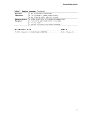
Feature Summary (continued) Expansion Capabilities Hardware Monitor Subsystem • One PCI Conventional bus connector • Two PCI Express x1 bus add-in card connector • One PCI Express x16 bus add-in card connector • Voltage sense to detect out of range power supply voltages • Thermal sense to detect out of range thermal values • Three fan headers • Three fan sense inputs used to monitor fan activity For information about Available configurations for the Desktop Board DG35EC Refer to Section 1.2, page 15 11 Product Description Table 1.
Feature Summary (continued) Expansion Capabilities Hardware Monitor Subsystem • One PCI Conventional bus connector • Two PCI Express x1 bus add-in card connector • One PCI Express x16 bus add-in card connector • Voltage sense to detect out of range power supply voltages • Thermal sense to detect out of range thermal values • Three fan headers • Three fan sense inputs used to monitor fan activity For information about Available configurations for the Desktop Board DG35EC Refer to Section 1.2, page 15 11 Product Description Table 1.
Product Specification
Page 15
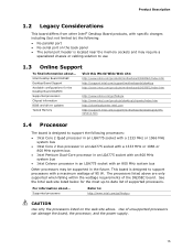
... http://support.intel.com/support/motherboards/desktop http://www.intel.com/products/motherboard/DG35EC/index.htm http://www.intel.com/go /findcpu CAUTION Use only the processors listed on the back panel • The serial port header is designed to -date list of supported processors. Use of unsupported processors can damage the board, the processor, and the power supply. 15...
... http://support.intel.com/support/motherboards/desktop http://www.intel.com/products/motherboard/DG35EC/index.htm http://www.intel.com/go /findcpu CAUTION Use only the processors listed on the back panel • The serial port header is designed to -date list of supported processors. Use of unsupported processors can damage the board, the processor, and the power supply. 15...


