Product Guide
Page 5
Contents 1 Desktop Board Features Supported Operating Systems 10 Desktop Board Components 11 Processor ...13 Main Memory...13 Intel® G31 Express Chipset 14 Intel® G33 Graphics Subsystem 15 Intel® GMA 3100 Graphics Controller (Intel® GMA 3100 15 Audio Subsystem 16 Legacy Input/Output (I/O) ...up Support 25 ENERGY STAR* Capable 25 Speaker...25 Battery ...25 Real-Time Clock 25 2 Installing and Replacing Desktop Board Components Before You Begin 27 Installation Precautions 28 Prevent Power Supply Overload 28 Observe Safety and Regulatory Requirements 28 Installing ...
Contents 1 Desktop Board Features Supported Operating Systems 10 Desktop Board Components 11 Processor ...13 Main Memory...13 Intel® G31 Express Chipset 14 Intel® G33 Graphics Subsystem 15 Intel® GMA 3100 Graphics Controller (Intel® GMA 3100 15 Audio Subsystem 16 Legacy Input/Output (I/O) ...up Support 25 ENERGY STAR* Capable 25 Speaker...25 Battery ...25 Real-Time Clock 25 2 Installing and Replacing Desktop Board Components Before You Begin 27 Installation Precautions 28 Prevent Power Supply Overload 28 Observe Safety and Regulatory Requirements 28 Installing ...
Product Guide
Page 6
Intel Desktop Board DG31PR Product Guide Installing and Removing a Processor 31 Installing a Processor 31 Installing the Processor Fan Heat Sink 34 Connecting the Processor Fan Heat Sink Cable 35 Removing the Processor 36 Installing and Removing Memory 36 Installing DIMMs 37 Removing DIMMs 39 Installing and Removing a PCI Express x16 Card 39... Battery Marking 65 European Union Declaration of Conformity Statement 66 Product Ecology Statements 67 Recycling Considerations 67 Lead-Free Desktop Board 69 EMC Regulations 71 Ensure Electromagnetic Compatibility (EMC) Compliance 72 vi
Intel Desktop Board DG31PR Product Guide Installing and Removing a Processor 31 Installing a Processor 31 Installing the Processor Fan Heat Sink 34 Connecting the Processor Fan Heat Sink Cable 35 Removing the Processor 36 Installing and Removing Memory 36 Installing DIMMs 37 Removing DIMMs 39 Installing and Removing a PCI Express x16 Card 39... Battery Marking 65 European Union Declaration of Conformity Statement 66 Product Ecology Statements 67 Recycling Considerations 67 Lead-Free Desktop Board 69 EMC Regulations 71 Ensure Electromagnetic Compatibility (EMC) Compliance 72 vi
Product Guide
Page 7
... DDR2 DIMMs 37 15. Removing a PCI Express x16 Card 41 18. Location of the Standby Power Indicator 24 4. Front Panel Intel High Definition Audio Header Signal Names 46 5. Alternate Front Panel Power LED Header 47 9. USB 2.0 Header Signal Names 48 11... Certifications 74 Figures 1. Remove the Processor from the Protective Processor Cover 33 10. Dual Channel Memory Configuration Example 36 14. Beep Codes 63 13. Lead-Free Board Markings 70 16. LAN Connector LEDs 17 3. Desktop Board DG31PR Components 11 2. Desktop Board DG31PR Mounting Screw Hole Locations 30 6....
... DDR2 DIMMs 37 15. Removing a PCI Express x16 Card 41 18. Location of the Standby Power Indicator 24 4. Front Panel Intel High Definition Audio Header Signal Names 46 5. Alternate Front Panel Power LED Header 47 9. USB 2.0 Header Signal Names 48 11... Certifications 74 Figures 1. Remove the Processor from the Protective Processor Cover 33 10. Dual Channel Memory Configuration Example 36 14. Beep Codes 63 13. Lead-Free Board Markings 70 16. LAN Connector LEDs 17 3. Desktop Board DG31PR Components 11 2. Desktop Board DG31PR Mounting Screw Hole Locations 30 6....
Product Guide
Page 9
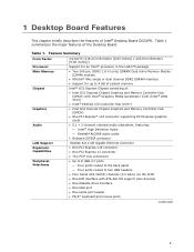
...Intel® processor in the LGA775 package • Two 240-pin, DDR2 1.8 V (only) SDRAM Dual Inline Memory Module (DIMM) sockets • 800/667 MHz single or dual channel DDR2 SDRAM interface • Support for up to 4 GB of system memory Intel® G31 Express Chipset consisting of the Desktop Board. Table 1. 1 Desktop Board... Features This chapter briefly describes the features of Intel® Desktop Board DG31PR.
...Intel® processor in the LGA775 package • Two 240-pin, DDR2 1.8 V (only) SDRAM Dual Inline Memory Module (DIMM) sockets • 800/667 MHz single or dual channel DDR2 SDRAM interface • Support for up to 4 GB of system memory Intel® G31 Express Chipset consisting of the Desktop Board. Table 1. 1 Desktop Board... Features This chapter briefly describes the features of Intel® Desktop Board DG31PR.
Product Guide
Page 13
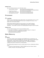
... screen at power up. The BIOS will see a notification to the Desktop Board may not function properly. Related Links: Go to the following links for more information about : • Desktop Board DG31PR http://www.intel.com/design/motherbd http://support.intel.com/support/motherboards/desktop • Supported processors http://www.intel.com/go/findCPU • Audio software and utilities http://www...
... screen at power up. The BIOS will see a notification to the Desktop Board may not function properly. Related Links: Go to the following links for more information about : • Desktop Board DG31PR http://www.intel.com/design/motherbd http://support.intel.com/support/motherboards/desktop • Supported processors http://www.intel.com/go/findCPU • Audio software and utilities http://www...
Product Guide
Page 14
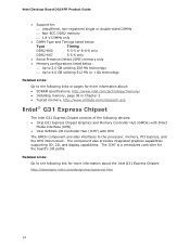
Related Links: Go to the processor, memory, PCI Express, and the DMI interconnect. Intel Desktop Board DG31PR Product Guide • Support for: ⎯ Unbuffered, non-registered single or double-sided DIMMs ⎯ Non-ECC DDR2 memory ⎯ 1.8 ....cmtlabs.com/mbsearch.asp Intel® G31 Express Chipset The Intel G31 Express Chipset consists of the following devices: • Intel G31 Express Chipset Graphics and Memory Controller Hub (GMCH) with Direct Media Interface (DMI) • Intel 82801G I /O paths. The ICH7 is a centralized controller for the board's I /O Controller Hub...
Related Links: Go to the processor, memory, PCI Express, and the DMI interconnect. Intel Desktop Board DG31PR Product Guide • Support for: ⎯ Unbuffered, non-registered single or double-sided DIMMs ⎯ Non-ECC DDR2 memory ⎯ 1.8 ....cmtlabs.com/mbsearch.asp Intel® G31 Express Chipset The Intel G31 Express Chipset consists of the following devices: • Intel G31 Express Chipset Graphics and Memory Controller Hub (GMCH) with Direct Media Interface (DMI) • Intel 82801G I /O paths. The ICH7 is a centralized controller for the board's I /O Controller Hub...
Product Guide
Page 18
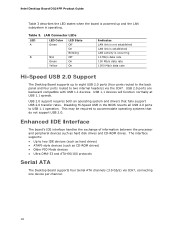
Intel Desktop Board DG31PR Product Guide Table 3 describes the LED states when the board is operating. USB 2.0 ports are backward compatible with USB 1.1 devices. USB 1.1 devices will function normally at USB 1.1 speeds. Disabling Hi-Speed USB in the ... to USB 1.1 operation. Enhanced IDE Interface The board's IDE interface handles the exchange of information between the processor and peripheral devices such as CD-ROM drives) • Older PIO Mode devices • Ultra DMA-33 and ATA-66/100 protocols Serial ATA The Desktop Board supports four Serial ATA channels (3.0 Gb/s) via ...
Intel Desktop Board DG31PR Product Guide Table 3 describes the LED states when the board is operating. USB 2.0 ports are backward compatible with USB 1.1 devices. USB 1.1 devices will function normally at USB 1.1 speeds. Disabling Hi-Speed USB in the ... to USB 1.1 operation. Enhanced IDE Interface The board's IDE interface handles the exchange of information between the processor and peripheral devices such as CD-ROM drives) • Older PIO Mode devices • Ultra DMA-33 and ATA-66/100 protocols Serial ATA The Desktop Board supports four Serial ATA channels (3.0 Gb/s) via ...

Product Guide
Page 21
... the power management and Plug and Play functions of ACPI with the Desktop Board requires an operating system that provides full ACPI support. 21 Desktop Board Features Hardware Monitoring and Fan Speed Control The features of the hardware ...monitoring and fan speed control include: • Monitoring of power supply voltages to detect levels above and below acceptable values • Fan speed controllers and sensors integrated into the legacy I/O controller • Thermal sensors in the processor...
... the power management and Plug and Play functions of ACPI with the Desktop Board requires an operating system that provides full ACPI support. 21 Desktop Board Features Hardware Monitoring and Fan Speed Control The features of the hardware ...monitoring and fan speed control include: • Monitoring of power supply voltages to detect levels above and below acceptable values • Fan speed controllers and sensors integrated into the legacy I/O controller • Thermal sensors in the processor...
Product Guide
Page 22
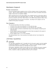
... control device. • All fan headers support closed-loop fan control that powers up of the computer through system control. The Desktop Board has a 4-pin processor fan header and two 3-pin chassis fan headers. LAN Wake Capabilities CAUTION For LAN wake capabilities, the 5 V standby line for... the power state it asserts a wake-up signal that can damage the power supply. The computer's response can turn off ). Intel Desktop Board DG31PR Product Guide Hardware Support Power Connectors ATX12V-compliant power supplies can be capable of delivering adequate +5 V standby current.
... control device. • All fan headers support closed-loop fan control that powers up of the computer through system control. The Desktop Board has a 4-pin processor fan header and two 3-pin chassis fan headers. LAN Wake Capabilities CAUTION For LAN wake capabilities, the 5 V standby line for... the power state it asserts a wake-up signal that can damage the power supply. The computer's response can turn off ). Intel Desktop Board DG31PR Product Guide Hardware Support Power Connectors ATX12V-compliant power supplies can be capable of delivering adequate +5 V standby current.
Product Guide
Page 27
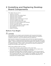
... This chapter tells you how to: • Install the I/O shield • Install and remove the Desktop Board • Install and remove a processor • Install and remove memory • Install and remove a PCI Express x16 card • Connect the diskette drive cable • Connect the IDE... regulatory compliance required for using an antistatic wrist strap and a conductive foam pad. If such a station is off. Some circuitry on the board can continue to operate even though the front panel power button is not available, you can provide some ESD protection by wearing an antistatic wrist...
... This chapter tells you how to: • Install the I/O shield • Install and remove the Desktop Board • Install and remove a processor • Install and remove memory • Install and remove a PCI Express x16 card • Connect the diskette drive cable • Connect the IDE... regulatory compliance required for using an antistatic wrist strap and a conductive foam pad. If such a station is off. Some circuitry on the board can continue to operate even though the front panel power button is not available, you can provide some ESD protection by wearing an antistatic wrist...
Product Guide
Page 28
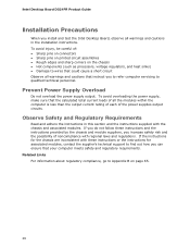
Intel Desktop Board DG31PR Product Guide Installation Precautions When you to refer computer servicing to ... provided by the chassis and module suppliers, you can ensure that instruct you install and test the Intel Desktop Board, observe all the modules within the computer is less than the output current rating of each of noncompliance... associated modules, contact the supplier's technical support to Appendix B on the chassis • Hot components (such as processors, voltage regulators, and heat sinks) • Damage to wires that could cause a short circuit Observe all warnings and...
Intel Desktop Board DG31PR Product Guide Installation Precautions When you to refer computer servicing to ... provided by the chassis and module suppliers, you can ensure that instruct you install and test the Intel Desktop Board, observe all the modules within the computer is less than the output current rating of each of noncompliance... associated modules, contact the supplier's technical support to Appendix B on the chassis • Hot components (such as processors, voltage regulators, and heat sinks) • Damage to wires that could cause a short circuit Observe all warnings and...
Product Guide
Page 31
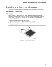
...; Open the socket lever by unplugging the power cord from the socket (Figure 6, A and B). Failure to the Desktop Board are given below. Observe the precautions in "Before You Begin" on page 24). To install a processor, follow these instructions: 1. Figure 6. Lift the Socket Lever 31 the standby power LED should not be lit (see...
...; Open the socket lever by unplugging the power cord from the socket (Figure 6, A and B). Failure to the Desktop Board are given below. Observe the precautions in "Before You Begin" on page 24). To install a processor, follow these instructions: 1. Figure 6. Lift the Socket Lever 31 the standby power LED should not be lit (see...

Product Guide
Page 32
Lift the Load Plate 4. Figure 7. Always replace the socket cover if the processor is removed from the load plate (Figure 8). Intel Desktop Board DG31PR Product Guide 3. Do not touch the socket contacts (Figure 7, B). Figure 8. Lift the load plate (Figure 7, A). Do not discard the protective socket cover. Remove the plastic protective socket cover from the socket. Remove the Protective Socket Cover 32
Lift the Load Plate 4. Figure 7. Always replace the socket cover if the processor is removed from the load plate (Figure 8). Intel Desktop Board DG31PR Product Guide 3. Do not touch the socket contacts (Figure 7, B). Figure 8. Lift the load plate (Figure 7, A). Do not discard the protective socket cover. Remove the plastic protective socket cover from the socket. Remove the Protective Socket Cover 32

Product Guide
Page 33
... (Figure 10, C). Figure 9. Do not discard the protective processor cover. Remove the Processor from the socket. Install the Processor 33 Lower the processor straight down without tilting or sliding it in Figure 10. Installing and Replacing Desktop Board Components 5. Remove the processor from the protective processor cover. Hold the processor only at the edges, being careful not to the...
... (Figure 10, C). Figure 9. Do not discard the protective processor cover. Remove the Processor from the socket. Install the Processor 33 Lower the processor straight down without tilting or sliding it in Figure 10. Installing and Replacing Desktop Board Components 5. Remove the processor from the protective processor cover. Hold the processor only at the edges, being careful not to the...

Product Guide
Page 34
Pressing down on how to attach the processor fan heat sink to the Desktop Board, refer to the boxed processor manual. 34 For instructions on the load plate (Figure 11, A), close and engage the socket lever (Figure 11, B). Intel Desktop Board DG31PR Product Guide 7. Figure 11. Close the Load Plate Installing the Processor Fan Heat Sink Desktop Board DG31PR has mounting holes for a processor fan heat sink.
Pressing down on how to attach the processor fan heat sink to the Desktop Board, refer to the boxed processor manual. 34 For instructions on the load plate (Figure 11, A), close and engage the socket lever (Figure 11, B). Intel Desktop Board DG31PR Product Guide 7. Figure 11. Close the Load Plate Installing the Processor Fan Heat Sink Desktop Board DG31PR has mounting holes for a processor fan heat sink.

Product Guide
Page 35
However, since the fan with a 4-pin connector as shown in Figure 12, A is recommended; A fan with a 3-pin connector cannot use the onboard fan control, the fan will always operate at full speed. Connecting the Processor Fan Heat Sink Cable to the 4-pin processor fan header (see Figure 12). however, a fan with a 3-pin connector (Figure 12, B) can be used. Figure 12. Installing and Replacing Desktop Board Components Connecting the Processor Fan Heat Sink Cable Connect the processor fan heat sink cable to the Processor Fan Header 35
However, since the fan with a 4-pin connector as shown in Figure 12, A is recommended; A fan with a 3-pin connector cannot use the onboard fan control, the fan will always operate at full speed. Connecting the Processor Fan Heat Sink Cable to the 4-pin processor fan header (see Figure 12). however, a fan with a 3-pin connector (Figure 12, B) can be used. Figure 12. Installing and Replacing Desktop Board Components Connecting the Processor Fan Heat Sink Cable Connect the processor fan heat sink cable to the Processor Fan Header 35
Product Guide
Page 36
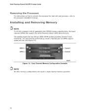
... Channel A and Channel B. Installing and Removing Memory NOTE To be fully compliant with all applicable Intel SDRAM memory specifications, the board requires DIMMs that support the Serial Presence Detect (SPD) data structure. Intel Desktop Board DG31PR Product Guide Removing the Processor For instructions on how to remove the processor fan heat sink and processor, refer to the processor installation manual.
... Channel A and Channel B. Installing and Removing Memory NOTE To be fully compliant with all applicable Intel SDRAM memory specifications, the board requires DIMMs that support the Serial Presence Detect (SPD) data structure. Intel Desktop Board DG31PR Product Guide Removing the Processor For instructions on how to remove the processor fan heat sink and processor, refer to the processor installation manual.

Product Guide
Page 51
... the system may not function properly. Connecting Power Supply Cables 1. Connect the 12 V processor core voltage power supply cable to the 2 x 12 pin connector. 3. Installing and Replacing Desktop Board Components Connecting Supply Power Cables CAUTION Failure to use an appropriate power supply and/or not ...connecting the 12 V (2 x 2 pin) power connector to the Desktop Board may result in "Before You Begin" on the Desktop Board is backwards compatible with ATX12V power supplies with 2 x 10 connectors. Connect the main power supply cable to the...
... the system may not function properly. Connecting Power Supply Cables 1. Connect the 12 V processor core voltage power supply cable to the 2 x 12 pin connector. 3. Installing and Replacing Desktop Board Components Connecting Supply Power Cables CAUTION Failure to use an appropriate power supply and/or not ...connecting the 12 V (2 x 2 pin) power connector to the Desktop Board may result in "Before You Begin" on the Desktop Board is backwards compatible with ATX12V power supplies with 2 x 10 connectors. Connect the main power supply cable to the...

Product Guide
Page 63
A Error Messages and Indicators Desktop Board DG31PR reports POST errors in two ways: • By sounding a beep code • By displaying an error message on ... Table 12 lists the BIOS codes. BIOS Error Messages Error Message PROCESSOR_THERMAL_TRIP_ERROR MULTI_BIT_ECC_ERROR SINGLE_BIT_ECC_ERROR CMOS_BATTERY_ERROR CMOS_CHECKSUM_ERROR CMOS_TIMER_ERROR MEMORY_SIZE_DECREASE_ERROR INTRUDER_DETECTION_ERROR SPD_TOLER_ERROR MEM_OPTIMAL_ERROR Explanation Processor was opened. The firmware has detected that a CMOS Checksum Error occurred. The firmware has detected that a Single-Bit ECC Error ...
A Error Messages and Indicators Desktop Board DG31PR reports POST errors in two ways: • By sounding a beep code • By displaying an error message on ... Table 12 lists the BIOS codes. BIOS Error Messages Error Message PROCESSOR_THERMAL_TRIP_ERROR MULTI_BIT_ECC_ERROR SINGLE_BIT_ECC_ERROR CMOS_BATTERY_ERROR CMOS_CHECKSUM_ERROR CMOS_TIMER_ERROR MEMORY_SIZE_DECREASE_ERROR INTRUDER_DETECTION_ERROR SPD_TOLER_ERROR MEM_OPTIMAL_ERROR Explanation Processor was opened. The firmware has detected that a CMOS Checksum Error occurred. The firmware has detected that a Single-Bit ECC Error ...


