Product Guide
Page 3
... Replacing Desktop Board Components: instructions on how to update the BIOS A Error Messages and Indicators: information about BIOS error messages and beep codes B Regulatory Compliance: information about board layout, component installation, BIOS update, and regulatory requirements for Intel® Desktop Board DG31PR. It is intended for other PC or embedded non-PC applications or other hardware components 3 Updating the BIOS: instructions on how to install the Desktop Board and other environments, such as Information Technology Equipment (I.T.E.) for use...
... Replacing Desktop Board Components: instructions on how to update the BIOS A Error Messages and Indicators: information about BIOS error messages and beep codes B Regulatory Compliance: information about board layout, component installation, BIOS update, and regulatory requirements for Intel® Desktop Board DG31PR. It is intended for other PC or embedded non-PC applications or other hardware components 3 Updating the BIOS: instructions on how to install the Desktop Board and other environments, such as Information Technology Equipment (I.T.E.) for use...
Product Guide
Page 5
... IDE Auto Configuration 19 PCI* and PCI Express* Auto Configuration 19 Security Passwords 20 Hardware Management Features 20 Hardware Monitoring and Fan Speed Control 21 Chassis Intrusion 21 Power Management Features 21 ACPI ...21 Hardware Support 22 Power Connectors 22 Fan Headers 22 LAN Wake Capabilities 22 Instantly Available PC Technology 23 +5 V Standby Power Indicator LED 23 Wake from USB 24 PME# Signal Wake-up Support 25 WAKE# Signal Wake-up Support 25 ENERGY STAR* Capable 25 Speaker...25 Battery ...25 Real-Time Clock 25 2 Installing and Replacing Desktop Board...
... IDE Auto Configuration 19 PCI* and PCI Express* Auto Configuration 19 Security Passwords 20 Hardware Management Features 20 Hardware Monitoring and Fan Speed Control 21 Chassis Intrusion 21 Power Management Features 21 ACPI ...21 Hardware Support 22 Power Connectors 22 Fan Headers 22 LAN Wake Capabilities 22 Instantly Available PC Technology 23 +5 V Standby Power Indicator LED 23 Wake from USB 24 PME# Signal Wake-up Support 25 WAKE# Signal Wake-up Support 25 ENERGY STAR* Capable 25 Speaker...25 Battery ...25 Real-Time Clock 25 2 Installing and Replacing Desktop Board...
Product Guide
Page 6
... Installing and Removing Memory 36 Installing DIMMs 37 Removing DIMMs 39 Installing and Removing a PCI Express x16 Card 39 Installing a PCI Express x16 Card 40 Removing the PCI Express x16 Card 41 Connecting the Diskette Drive Cable 42 Connecting the IDE Cable 43 Connecting the Serial ATA (SATA) Cables 44 Connecting to the Internal Headers and Connectors 45 Connecting to the Front Panel Audio Header 46 Connecting to the S/PDIF Connector 46 Connecting to the Chassis Intrusion Header 46 Connecting to the Serial Port Header 47 Connecting to the Alternate Front Panel Power LED Header...
... Installing and Removing Memory 36 Installing DIMMs 37 Removing DIMMs 39 Installing and Removing a PCI Express x16 Card 39 Installing a PCI Express x16 Card 40 Removing the PCI Express x16 Card 41 Connecting the Diskette Drive Cable 42 Connecting the IDE Cable 43 Connecting the Serial ATA (SATA) Cables 44 Connecting to the Internal Headers and Connectors 45 Connecting to the Front Panel Audio Header 46 Connecting to the S/PDIF Connector 46 Connecting to the Chassis Intrusion Header 46 Connecting to the Serial Port Header 47 Connecting to the Alternate Front Panel Power LED Header...
Product Guide
Page 7
... Processor Fan Header ..........35 13. Dual Channel Memory Configuration Example 36 14. Back Panel Audio Connectors 49 23. LAN Connector LEDs 18 4. Front Panel Intel High Definition Audio Header Signal Names 46 5. BIOS Error Messages 63 14. Desktop Board DG31PR Components 11 2. Location of the Chassis Fan Headers 50 24. Use DDR2 DIMMs 37 15. Connecting the Diskette Drive Cable 42 19. Connecting the IDE Cable 43 20. Location of the BIOS Configuration Jumper Block 52 26. Removing the Battery 58 Tables 1. S/PDIF Connector 46 6. Serial Port Header Signal...
... Processor Fan Header ..........35 13. Dual Channel Memory Configuration Example 36 14. Back Panel Audio Connectors 49 23. LAN Connector LEDs 18 4. Front Panel Intel High Definition Audio Header Signal Names 46 5. BIOS Error Messages 63 14. Desktop Board DG31PR Components 11 2. Location of the Chassis Fan Headers 50 24. Use DDR2 DIMMs 37 15. Connecting the Diskette Drive Cable 42 19. Connecting the IDE Cable 43 20. Location of the BIOS Configuration Jumper Block 52 26. Removing the Battery 58 Tables 1. S/PDIF Connector 46 6. Serial Port Header Signal...
Product Guide
Page 9
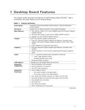
...) • One PCI Express* x16 connector supporting PCI Express graphics cards • 5.1 + 2-channel onboard audio subsystem, featuring: ― Intel® High Definition Audio ― Realtek*ALC888 audio codec • Onboard S/PDIF connector Realtek 8111-GR Gigabit Ethernet Controller • One PCI Express x16 connector • One PCI Express x1 connector • Two PCI* bus connectors • Up to 8 USB 2.0 ports ― Four ports routed to the back panel ― Four ports routed to 4 GB of system memory Intel® G31 Express Chipset consisting of the Desktop Board. Table...
...) • One PCI Express* x16 connector supporting PCI Express graphics cards • 5.1 + 2-channel onboard audio subsystem, featuring: ― Intel® High Definition Audio ― Realtek*ALC888 audio codec • Onboard S/PDIF connector Realtek 8111-GR Gigabit Ethernet Controller • One PCI Express x16 connector • One PCI Express x1 connector • Two PCI* bus connectors • Up to 8 USB 2.0 ports ― Four ports routed to the back panel ― Four ports routed to 4 GB of system memory Intel® G31 Express Chipset consisting of the Desktop Board. Table...
Product Guide
Page 10
...; Wake on USB, PCI Express, LAN, and front panel • ENERGY STAR* capable Hardware Monitor • Voltage sense to detect out of range power supply voltages • Thermal sense to detect out of range temperatures • Three fan headers • Three fan sense inputs to monitor fan speed Related Links: For more information about Desktop Board DG31PR, including the Technical Product Specification (TPS), BIOS updates, and device drivers, go to: http://support.intel.com/support/motherboards/desktop/ Supported Operating Systems The Desktop Board supports the...
...; Wake on USB, PCI Express, LAN, and front panel • ENERGY STAR* capable Hardware Monitor • Voltage sense to detect out of range power supply voltages • Thermal sense to detect out of range temperatures • Three fan headers • Three fan sense inputs to monitor fan speed Related Links: For more information about Desktop Board DG31PR, including the Technical Product Specification (TPS), BIOS updates, and device drivers, go to: http://support.intel.com/support/motherboards/desktop/ Supported Operating Systems The Desktop Board supports the...
Product Guide
Page 13
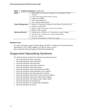
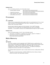
.... 13 The BIOS will see a notification to this effect on installing or upgrading the processor, page 31 in Chapter 2 • Supported processors for Desktop Board DG31PR, http://www.intel.com/go /findCPU • Audio software and utilities http://www.intel.com/design/motherbd • LAN software and drivers http://www.intel.com/design/motherbd Processor CAUTION Failure to use an appropriate power supply and/or not connecting the 12 V (2 x 2 pin) power connector to the Desktop Board through the LGA775 socket.
.... 13 The BIOS will see a notification to this effect on installing or upgrading the processor, page 31 in Chapter 2 • Supported processors for Desktop Board DG31PR, http://www.intel.com/go /findCPU • Audio software and utilities http://www.intel.com/design/motherbd • LAN software and drivers http://www.intel.com/design/motherbd Processor CAUTION Failure to use an appropriate power supply and/or not connecting the 12 V (2 x 2 pin) power connector to the Desktop Board through the LGA775 socket.
Product Guide
Page 16
... audio connectors • Onboard audio header/connector: ⎯ Intel High Definition audio front panel audio header ⎯ Onboard S/PDIF connector The audio subsystem supports the following features: • A signal-to-noise (S/N) ratio of 95 dB • Independent multi-streaming 5.1 audio (using the back panel audio connectors) and stereo (using the Intel High Definition front panel audio header) Related Links: Go to the following link or pages for more information about: • Audio drivers and utilities http://support.intel.com/support/motherboards/desktop/ • The location...
... audio connectors • Onboard audio header/connector: ⎯ Intel High Definition audio front panel audio header ⎯ Onboard S/PDIF connector The audio subsystem supports the following features: • A signal-to-noise (S/N) ratio of 95 dB • Independent multi-streaming 5.1 audio (using the back panel audio connectors) and stereo (using the Intel High Definition front panel audio header) Related Links: Go to the following link or pages for more information about: • Audio drivers and utilities http://support.intel.com/support/motherboards/desktop/ • The location...
Product Guide
Page 17
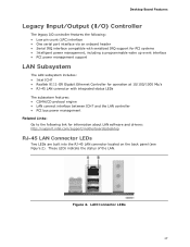
... Mb/s • RJ-45 LAN connector with integrated status LEDs The subsystem features: • CSMA/CD protocol engine • LAN connect interface between ICH7 and the LAN controller • PCI bus power management Related Links: Go to the following link for information about LAN software and drivers: http://support.intel.com/support/motherboards/desktop RJ-45 LAN Connector LEDs Two LEDs are built into the RJ-45 LAN connector located on the back panel (see Figure 2).
... Mb/s • RJ-45 LAN connector with integrated status LEDs The subsystem features: • CSMA/CD protocol engine • LAN connect interface between ICH7 and the LAN controller • PCI bus power management Related Links: Go to the following link for information about LAN software and drivers: http://support.intel.com/support/motherboards/desktop RJ-45 LAN Connector LEDs Two LEDs are built into the RJ-45 LAN connector located on the back panel (see Figure 2).
Product Guide
Page 18
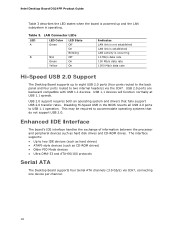
...-Speed USB 2.0 Support The Desktop Board supports up and the LAN subsystem is powered up to eight USB 2.0 ports (four ports routed to the back panel and four ports routed to two IDE devices (such as hard drives) • ATAPI-style devices (such as hard disk drives and CD-ROM drives. Disabling Hi-Speed USB in the BIOS reverts all USB 2.0 ports to accommodate operating systems that fully support USB 2.0 transfer rates. USB 1.1 devices will function normally at USB 1.1 speeds. This may be required to USB...
...-Speed USB 2.0 Support The Desktop Board supports up and the LAN subsystem is powered up to eight USB 2.0 ports (four ports routed to the back panel and four ports routed to two IDE devices (such as hard drives) • ATAPI-style devices (such as hard disk drives and CD-ROM drives. Disabling Hi-Speed USB in the BIOS reverts all USB 2.0 ports to accommodate operating systems that fully support USB 2.0 transfer rates. USB 1.1 devices will function normally at USB 1.1 speeds. This may be required to USB...
Product Guide
Page 19
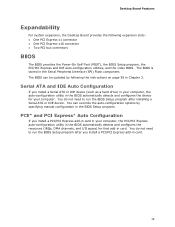
... BIOS Setup program. You do not need to run the BIOS Setup program after you install a PCI/PCI Express add-in card in your computer. The BIOS can override the auto-configuration options by following expansion slots: • One PCI Express x1 connector • One PCI Express x16 connector • Two PCI bus connectors BIOS The BIOS provides the Power-On Self-Test (POST), the BIOS Setup program, the PCI/PCI Express and IDE auto-configuration utilities, and the video BIOS. You can be updated by specifying manual configuration in the Serial...
... BIOS Setup program. You do not need to run the BIOS Setup program after you install a PCI/PCI Express add-in card in your computer. The BIOS can override the auto-configuration options by following expansion slots: • One PCI Express x1 connector • One PCI Express x16 connector • Two PCI bus connectors BIOS The BIOS provides the Power-On Self-Test (POST), the BIOS Setup program, the PCI/PCI Express and IDE auto-configuration utilities, and the video BIOS. You can be updated by specifying manual configuration in the Serial...

Product Guide
Page 20
... view and change all Setup options. If only the supervisor password is booted. Related Links: For instructions on resetting the password, see Clearing Passwords on whether the supervisor or user password was entered. • Setting a user password restricts who can boot the computer. Intel Desktop Board DG31PR Product Guide Security Passwords The BIOS includes security features that restrict whether the BIOS Setup program can be compatible with the following : • Fan speed monitoring and control • Thermal and voltage monitoring • Chassis intrusion detection...
... view and change all Setup options. If only the supervisor password is booted. Related Links: For instructions on resetting the password, see Clearing Passwords on whether the supervisor or user password was entered. • Setting a user password restricts who can boot the computer. Intel Desktop Board DG31PR Product Guide Security Passwords The BIOS includes security features that restrict whether the BIOS Setup program can be compatible with the following : • Fan speed monitoring and control • Thermal and voltage monitoring • Chassis intrusion detection...
Product Guide
Page 22
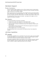
... was in the BIOS Setup program's Boot menu. When an ACPI-enabled computer receives the correct command, the power supply removes all non-standby voltages. The Desktop Board has two power connectors. See Figure 24 on or off the computer power through a network. LAN wakeup capabilities enable remote wake-up the computer. 22 Intel Desktop Board DG31PR Product Guide Hardware Support Power Connectors ATX12V-compliant power supplies can damage the power supply. Fan Headers The function/operation of the fans is wired to provide adequate...
... was in the BIOS Setup program's Boot menu. When an ACPI-enabled computer receives the correct command, the power supply removes all non-standby voltages. The Desktop Board has two power connectors. See Figure 24 on or off the computer power through a network. LAN wakeup capabilities enable remote wake-up the computer. 22 Intel Desktop Board DG31PR Product Guide Hardware Support Power Connectors ATX12V-compliant power supplies can damage the power supply. Fan Headers The function/operation of the fans is wired to provide adequate...

Product Guide
Page 23
... technology enables the board to enter the ACPI S3 (Suspend-toRAM) sleep state. If the standby current necessary to support multiple wake events from the PCI and/or USB buses exceeds power supply capacity, the Desktop Board may lose register settings stored in the S3 sleep state, the computer will appear to be off. Failure to do so could damage the board and any devices connected to the board. The Desktop Board supports the PCI Bus Power...
... technology enables the board to enter the ACPI S3 (Suspend-toRAM) sleep state. If the standby current necessary to support multiple wake events from the PCI and/or USB buses exceeds power supply capacity, the Desktop Board may lose register settings stored in the S3 sleep state, the computer will appear to be off. Failure to do so could damage the board and any devices connected to the board. The Desktop Board supports the PCI Bus Power...
Product Guide
Page 27
..., networks, or modems before you how to: • Install the I/O shield • Install and remove the Desktop Board • Install and remove a processor • Install and remove memory • Install and remove a PCI Express x16 card • Connect the diskette drive cable • Connect the IDE and Serial ATA cables • Connect to the internal headers and connectors • Connect to a metal part of the procedures described in this chapter only at an ESD workstation using and modifying electronic equipment. 2 Installing and Replacing Desktop Board...
..., networks, or modems before you how to: • Install the I/O shield • Install and remove the Desktop Board • Install and remove a processor • Install and remove memory • Install and remove a PCI Express x16 card • Connect the diskette drive cable • Connect the IDE and Serial ATA cables • Connect to the internal headers and connectors • Connect to a metal part of the procedures described in this chapter only at an ESD workstation using and modifying electronic equipment. 2 Installing and Replacing Desktop Board...

Product Guide
Page 35
A fan with a 3-pin connector cannot use the onboard fan control, the fan will always operate at full speed. Connecting the Processor Fan Heat Sink Cable to the 4-pin processor fan header (see Figure 12). However, since the fan with a 4-pin connector as shown in Figure 12, A is recommended; however, a fan with a 3-pin connector (Figure 12, B) can be used. Installing and Replacing Desktop Board Components Connecting the Processor Fan Heat Sink Cable Connect the processor fan heat sink cable to the Processor Fan Header 35 Figure 12.
A fan with a 3-pin connector cannot use the onboard fan control, the fan will always operate at full speed. Connecting the Processor Fan Heat Sink Cable to the 4-pin processor fan header (see Figure 12). However, since the fan with a 4-pin connector as shown in Figure 12, A is recommended; however, a fan with a 3-pin connector (Figure 12, B) can be used. Installing and Replacing Desktop Board Components Connecting the Processor Fan Heat Sink Cable Connect the processor fan heat sink cable to the Processor Fan Header 35 Figure 12.
Product Guide
Page 53
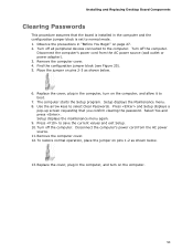
Turn off all peripheral devices connected to select Clear Passwords. The computer starts the Setup program. Use the arrow keys to the computer. Select Yes and press . Turn off the computer. Observe the precautions in "Before You Begin" on pins 1-2 as shown below . 13. Find the configuration jumper block (see Figure 25). 5. Setup displays the Maintenance menu. 8. To restore normal operation, place the jumper on page 27. 2. Replace the...
Turn off all peripheral devices connected to select Clear Passwords. The computer starts the Setup program. Use the arrow keys to the computer. Select Yes and press . Turn off the computer. Observe the precautions in "Before You Begin" on pins 1-2 as shown below . 13. Find the configuration jumper block (see Figure 25). 5. Setup displays the Maintenance menu. 8. To restore normal operation, place the jumper on page 27. 2. Replace the...

Product Guide
Page 59
... a removable USB device. This step is included in the dialog boxes to update the BIOS by pressing the key after the Power-On Self-Test (POST) memory test begins and before the operating system boot begins. Your system will be used to your hard drive where it was saved. 3 Updating the BIOS The BIOS Setup program can be rebooted at the last Express BIOS Update window. 5. Updating the BIOS with the Intel Express BIOS Update utility: 1. Download the file to...
... a removable USB device. This step is included in the dialog boxes to update the BIOS by pressing the key after the Power-On Self-Test (POST) memory test begins and before the operating system boot begins. Your system will be used to your hard drive where it was saved. 3 Updating the BIOS The BIOS Setup program can be rebooted at the last Express BIOS Update window. 5. Updating the BIOS with the Intel Express BIOS Update utility: 1. Download the file to...
Product Guide
Page 60
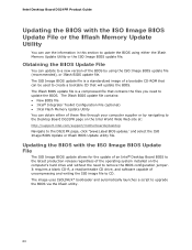
...; Desktop Board BIOS to the latest production release regardless of the operating system installed on the Intel World Wide Web site at: http://support.intel.com/support/motherboards/desktop Navigate to the DG31PR page, click "[view] Latest BIOS updates," and select the ISO Image BIOS Update or Iflash BIOS Update utility file. The image uses ISOLINUX* bootloader and automatically launches a script to CD. Obtaining the BIOS Update File You can be used to remove the BIOS configuration jumper...
...; Desktop Board BIOS to the latest production release regardless of the operating system installed on the Intel World Wide Web site at: http://support.intel.com/support/motherboards/desktop Navigate to the DG31PR page, click "[view] Latest BIOS updates," and select the ISO Image BIOS Update or Iflash BIOS Update utility file. The image uses ISOLINUX* bootloader and automatically launches a script to CD. Obtaining the BIOS Update File You can be used to remove the BIOS configuration jumper...
Product Guide
Page 62
...://support.intel.com/support/motherboards/desktop/sb/CS-022312.htm 62 Configure the BIOS or use the F10 option during POST to boot to a bootable USB flash drive or other bootable USB media. 2. Related Links: For more information about updating the Intel Desktop Board BIOS or recovering from the USB device and manually update the BIOS. Manually run the IFLASH.EXE file from a BIOS update failure, go to BIOS size and recovery requirements, a CD-R with the .BIO file in the root directory will interrupt the BIOS update...
...://support.intel.com/support/motherboards/desktop/sb/CS-022312.htm 62 Configure the BIOS or use the F10 option during POST to boot to a bootable USB flash drive or other bootable USB media. 2. Related Links: For more information about updating the Intel Desktop Board BIOS or recovering from the USB device and manually update the BIOS. Manually run the IFLASH.EXE file from a BIOS update failure, go to BIOS size and recovery requirements, a CD-R with the .BIO file in the root directory will interrupt the BIOS update...


