Product Guide
Page 5
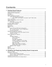
Contents 1 Desktop Board Features Supported Operating Systems 10 Desktop Board Components 11 Processor ...13 Main Memory...13 Intel® G31 Express Chipset 14 Intel® G33 Graphics Subsystem 15 Intel® GMA 3100 Graphics Controller (Intel® GMA ...3100 15 Audio Subsystem 16 Legacy Input/Output (I/O) Controller 17 LAN Subsystem 17 RJ-45 LAN Connector LEDs 17 Hi-Speed USB 2.0 Support 18 Enhanced IDE Interface 18 Serial ATA...18 Expandability...19 BIOS ...19 Serial ATA and IDE Auto Configuration 19 PCI* and PCI Express...
Contents 1 Desktop Board Features Supported Operating Systems 10 Desktop Board Components 11 Processor ...13 Main Memory...13 Intel® G31 Express Chipset 14 Intel® G33 Graphics Subsystem 15 Intel® GMA 3100 Graphics Controller (Intel® GMA ...3100 15 Audio Subsystem 16 Legacy Input/Output (I/O) Controller 17 LAN Subsystem 17 RJ-45 LAN Connector LEDs 17 Hi-Speed USB 2.0 Support 18 Enhanced IDE Interface 18 Serial ATA...18 Expandability...19 BIOS ...19 Serial ATA and IDE Auto Configuration 19 PCI* and PCI Express...
Product Guide
Page 6
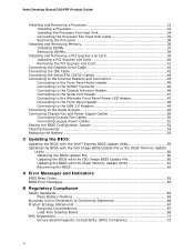
Intel Desktop Board DG31PR Product Guide Installing and Removing a Processor 31 Installing a Processor 31 Installing the Processor Fan Heat Sink 34 Connecting the Processor Fan Heat Sink Cable 35 Removing the Processor 36 Installing and Removing Memory 36 Installing DIMMs 37 Removing DIMMs 39 Installing and Removing a PCI Express x16 Card 39 Installing a PCI Express... x16 Card 40 Removing the PCI Express x16 Card 41 Connecting the Diskette Drive Cable 42 Connecting ...
Intel Desktop Board DG31PR Product Guide Installing and Removing a Processor 31 Installing a Processor 31 Installing the Processor Fan Heat Sink 34 Connecting the Processor Fan Heat Sink Cable 35 Removing the Processor 36 Installing and Removing Memory 36 Installing DIMMs 37 Removing DIMMs 39 Installing and Removing a PCI Express x16 Card 39 Installing a PCI Express... x16 Card 40 Removing the PCI Express x16 Card 41 Connecting the Diskette Drive Cable 42 Connecting ...
Product Guide
Page 7
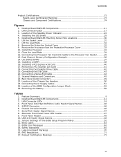
... 2. Lift the Load Plate 32 8. Removing a PCI Express x16 Card 41 18. Removing the Battery 58 Tables 1. Alternate Front Panel Power LED Header 47 9. Safety Standards 65 15. Contents Product Certifications 73 Board-Level Certification Markings 73 Chassis and Component Certifications 74 Figures 1. LAN Connector LEDs 17 3. Desktop Board DG31PR Mounting Screw Hole Locations 30 6. Remove...
... 2. Lift the Load Plate 32 8. Removing a PCI Express x16 Card 41 18. Removing the Battery 58 Tables 1. Alternate Front Panel Power LED Header 47 9. Safety Standards 65 15. Contents Product Certifications 73 Board-Level Certification Markings 73 Chassis and Component Certifications 74 Figures 1. LAN Connector LEDs 17 3. Desktop Board DG31PR Mounting Screw Hole Locations 30 6. Remove...
Product Guide
Page 9
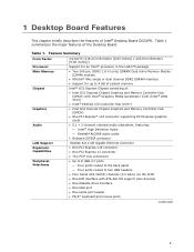
...8226; Intel G31 Express Chipset Graphics and Memory Controller Hub (GMCH) with Intel® Graphics Media Accelerator 3100 (Intel® GMA 3100) • Intel® 82801G I/O Controller Hub (ICH7) • Intel G31 Express Chipset Graphics and Memory Controller Hub (GMCH) • One PCI Express* x16 connector supporting PCI Express graphics cards... interface • Support for up to 4 GB of system memory Intel® G31 Express Chipset consisting of the Desktop Board. 1 Desktop Board Features This chapter briefly describes the features of Intel® Desktop Board DG31PR. Table 1.
...8226; Intel G31 Express Chipset Graphics and Memory Controller Hub (GMCH) with Intel® Graphics Media Accelerator 3100 (Intel® GMA 3100) • Intel® 82801G I/O Controller Hub (ICH7) • Intel G31 Express Chipset Graphics and Memory Controller Hub (GMCH) • One PCI Express* x16 connector supporting PCI Express graphics cards... interface • Support for up to 4 GB of system memory Intel® G31 Express Chipset consisting of the Desktop Board. 1 Desktop Board Features This chapter briefly describes the features of Intel® Desktop Board DG31PR. Table 1.
Product Guide
Page 10
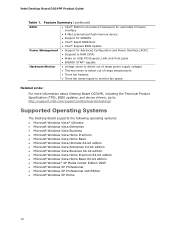
...; Support for SMBIOS • Intel® Rapid BIOS Boot • Intel® Express BIOS Update Power Management • Support for Advanced Configuration and Power Interface (ACPI) • Suspend to RAM (STR) • Wake on USB, PCI Express, LAN, and front panel ... speed Related Links: For more information about Desktop Board DG31PR, including the Technical Product Specification (TPS), BIOS updates, and device drivers, go to: http://support.intel.com/support/motherboards/desktop/ Supported Operating Systems The Desktop Board supports the following operating systems: • Microsoft...
...; Support for SMBIOS • Intel® Rapid BIOS Boot • Intel® Express BIOS Update Power Management • Support for Advanced Configuration and Power Interface (ACPI) • Suspend to RAM (STR) • Wake on USB, PCI Express, LAN, and front panel ... speed Related Links: For more information about Desktop Board DG31PR, including the Technical Product Specification (TPS), BIOS updates, and device drivers, go to: http://support.intel.com/support/motherboards/desktop/ Supported Operating Systems The Desktop Board supports the following operating systems: • Microsoft...
Product Guide
Page 14
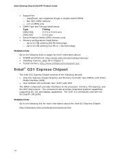
... is a centralized controller for more information about the Intel G31 Express Chipset: http://developer.intel.com/design/nav/pcserver.htm 14 Related Links: Go to the following devices: • Intel G31 Express Chipset Graphics and Memory Controller Hub (GMCH) with Direct Media Interface (DMI) • Intel 82801G I /O paths. Intel Desktop Board DG31PR Product Guide • Support for: ⎯ Unbuffered, non...
... is a centralized controller for more information about the Intel G31 Express Chipset: http://developer.intel.com/design/nav/pcserver.htm 14 Related Links: Go to the following devices: • Intel G31 Express Chipset Graphics and Memory Controller Hub (GMCH) with Direct Media Interface (DMI) • Intel 82801G I /O paths. Intel Desktop Board DG31PR Product Guide • Support for: ⎯ Unbuffered, non...
Product Guide
Page 15
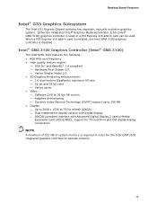
...; GMA 3100) graphics controller is required in card is installed, the Intel GMA 3100 graphics controller is disabled. Desktop Board Features Intel® G33 Graphics Subsystem The Intel G31 Express Chipset contains two separate, mutually exclusive graphics options. When a PCI Express x16 add-in order for TV-out/TV-in and DVI digital display connections NOTE A minimum of...
...; GMA 3100) graphics controller is required in card is installed, the Intel GMA 3100 graphics controller is disabled. Desktop Board Features Intel® G33 Graphics Subsystem The Intel G31 Express Chipset contains two separate, mutually exclusive graphics options. When a PCI Express x16 add-in order for TV-out/TV-in and DVI digital display connections NOTE A minimum of...
Product Guide
Page 19
... stored in the Serial Peripheral Interface (SPI) Flash component. PCI* and PCI Express* Auto Configuration If you install a PCI/PCI Express add-in card in your computer. You can be updated by specifying manual configuration in the BIOS Setup program. Desktop Board Features Expandability For system expansion, the Desktop Board provides the following the instructions on page 59 in Chapter...
... stored in the Serial Peripheral Interface (SPI) Flash component. PCI* and PCI Express* Auto Configuration If you install a PCI/PCI Express add-in card in your computer. You can be updated by specifying manual configuration in the BIOS Setup program. Desktop Board Features Expandability For system expansion, the Desktop Board provides the following the instructions on page 59 in Chapter...
Product Guide
Page 25
...On Self-Test (POST). WAKE# Signal Wake-up Support When the PME# signal on the PCI bus is asserted, the computer wakes from an ACPI S2, S3, S4, or S5 state. Currently Intel Desktop Boards are capable of -day clock and 100-year calendar. Go to replace the battery. ENERGY STAR... Energy and the US Environmental Protection Agency revised the ENERGY STAR requirements. Go to define the new requirements. Desktop Board Features PME# Signal Wake-up Support When the WAKE# signal on the PCI Express bus is asserted, the computer wakes from an ACPI S3, S4, or S5 state. Battery A battery ...
...On Self-Test (POST). WAKE# Signal Wake-up Support When the PME# signal on the PCI bus is asserted, the computer wakes from an ACPI S2, S3, S4, or S5 state. Currently Intel Desktop Boards are capable of -day clock and 100-year calendar. Go to replace the battery. ENERGY STAR... Energy and the US Environmental Protection Agency revised the ENERGY STAR requirements. Go to define the new requirements. Desktop Board Features PME# Signal Wake-up Support When the WAKE# signal on the PCI Express bus is asserted, the computer wakes from an ACPI S3, S4, or S5 state. Battery A battery ...
Product Guide
Page 27
...modems before you how to: • Install the I/O shield • Install and remove the Desktop Board • Install and remove a processor • Install and remove memory • Install and remove a PCI Express x16 card • Connect the diskette drive cable • Connect the IDE and Serial ATA cables... compliance required for using an antistatic wrist strap and a conductive foam pad. If such a station is off. 2 Installing and Replacing Desktop Board Components This chapter tells you begin: • Always follow the steps in each procedure in the correct order. • Set up ...
...modems before you how to: • Install the I/O shield • Install and remove the Desktop Board • Install and remove a processor • Install and remove memory • Install and remove a PCI Express x16 card • Connect the diskette drive cable • Connect the IDE and Serial ATA cables... compliance required for using an antistatic wrist strap and a conductive foam pad. If such a station is off. 2 Installing and Replacing Desktop Board Components This chapter tells you begin: • Always follow the steps in each procedure in the correct order. • Set up ...
Product Guide
Page 39
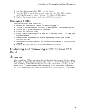
... DIMMs To remove a DIMM, follow these steps: 1. Depending on the Desktop Board, ensure that the card is inserted, push down on page 27. 2. Make sure the clips are firmly in the PCI Express x16 connector before you removed or disconnected to the computer. Observe the precautions... spread the retaining clips at each end of the socket. 6. Installing and Replacing Desktop Board Components 7. Insert the bottom edge of the power supply, certain Desktop Board components and/or traces may result across the PCI Express connector pins. Turn off the computer. 3. Hold the DIMM by the edges,...
... DIMMs To remove a DIMM, follow these steps: 1. Depending on the Desktop Board, ensure that the card is inserted, push down on page 27. 2. Make sure the clips are firmly in the PCI Express x16 connector before you removed or disconnected to the computer. Observe the precautions... spread the retaining clips at each end of the socket. 6. Installing and Replacing Desktop Board Components 7. Insert the bottom edge of the power supply, certain Desktop Board components and/or traces may result across the PCI Express connector pins. Turn off the computer. 3. Hold the DIMM by the edges,...
Product Guide
Page 40
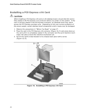
...the card until it is fully seated in the PCI Express x16 connector before you power on the system. Figure 16. Installing a PCI Express x16 Card 40 Depending on page 27. 2. Intel Desktop Board DG31PR Product Guide Installing a PCI Express x16 Card CAUTION When installing a PCI Express x16 card on the desktop board, ensure that the card is completely seated in the... (Figure 16, B). If the card is not fully seated in "Before You Begin" on the over-current protection of the power supply, certain desktop board components and/or traces may result across the PCI Express connector pins.
...the card until it is fully seated in the PCI Express x16 connector before you power on the system. Figure 16. Installing a PCI Express x16 Card 40 Depending on page 27. 2. Intel Desktop Board DG31PR Product Guide Installing a PCI Express x16 Card CAUTION When installing a PCI Express x16 card on the desktop board, ensure that the card is completely seated in the... (Figure 16, B). If the card is not fully seated in "Before You Begin" on the over-current protection of the power supply, certain desktop board components and/or traces may result across the PCI Express connector pins.
Product Guide
Page 41
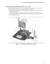
Remove the screw (Figure 17, A) that secures the card's metal bracket to remove the PCI Express x16 card from the connector (Figure 17, C). 4. Pull the card straight up. Installing and Replacing Desktop Board Components Removing the PCI Express x16 Card Follow these instructions to the chassis back panel. 3. This will release the card from the connector: 1. Removing a PCI Express x16 Card 41 Observe the precautions in the notch (Figure 17, B). Figure 17. Push the card ejector lever down using the tip of a pencil or similar tool in "Before You Begin" on page 27. 2.
Remove the screw (Figure 17, A) that secures the card's metal bracket to remove the PCI Express x16 card from the connector (Figure 17, C). 4. Pull the card straight up. Installing and Replacing Desktop Board Components Removing the PCI Express x16 Card Follow these instructions to the chassis back panel. 3. This will release the card from the connector: 1. Removing a PCI Express x16 Card 41 Observe the precautions in the notch (Figure 17, B). Figure 17. Push the card ejector lever down using the tip of a pencil or similar tool in "Before You Begin" on page 27. 2.

