Product Guide
Page 3
... product features 2 Installing and Replacing Desktop Board Components: instructions on how to install the Desktop Board and other environments, such as Information Technology Equipment (I.T.E.) for use in this Product Guide are evaluated as medical, industrial, alarm systems, test equipment, etc. Document Organization The chapters in personal computers (PC) for Intel® Desktop Board D945GSEJT. Intended Audience The Product Guide...
... product features 2 Installing and Replacing Desktop Board Components: instructions on how to install the Desktop Board and other environments, such as Information Technology Equipment (I.T.E.) for use in this Product Guide are evaluated as medical, industrial, alarm systems, test equipment, etc. Document Organization The chapters in personal computers (PC) for Intel® Desktop Board D945GSEJT. Intended Audience The Product Guide...
Product Guide
Page 5
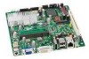
Contents 1 Desktop Board Features Desktop Board Components 12 Processor ...14 System Memory 14 Mobile Intel® 945GSE Express Chipset 14 Intel 945GSE Graphics Subsystem 15 Operating System Support 16 Onboard Audio Subsystem 16 Legacy Input/Output (I/O) Controller 17 ...ACPI ...22 Hardware Support 22 ENERGY STAR*, e-Standby, and EuP Compliance 25 Battery ...25 Real-Time Clock 25 2 Installing and Replacing Desktop Board Components Before You Begin 27 Installation Precautions 28 Prevent Power Supply Overload 28 Observe Safety and Regulatory Requirements 28 Installing the I/O Shield...
Contents 1 Desktop Board Features Desktop Board Components 12 Processor ...14 System Memory 14 Mobile Intel® 945GSE Express Chipset 14 Intel 945GSE Graphics Subsystem 15 Operating System Support 16 Onboard Audio Subsystem 16 Legacy Input/Output (I/O) Controller 17 ...ACPI ...22 Hardware Support 22 ENERGY STAR*, e-Standby, and EuP Compliance 25 Battery ...25 Real-Time Clock 25 2 Installing and Replacing Desktop Board Components Before You Begin 27 Installation Precautions 28 Prevent Power Supply Overload 28 Observe Safety and Regulatory Requirements 28 Installing the I/O Shield...

Product Guide
Page 25
... STAR Specification Computer Type v4.0 Desktop Computer v4.0 Integrated Computer v5.0 v5.0 Desktop Computer Integrated Desktop Computer Required States Idle State (... the clock current when the computer is turned off . 25 Desktop Board Features ENERGY STAR*, e-Standby, and EuP Compliance Intel Desktop Board D945GSEJT meets the ENERGY STAR requirements listed in Table 4 when used...Clock The Desktop Board includes a time-of Korea e-Standby program • European Union Energy using Products (EuP) directive Battery A coin-cell battery on how to http://www.intel.com/go to replace the ...
... STAR Specification Computer Type v4.0 Desktop Computer v4.0 Integrated Computer v5.0 v5.0 Desktop Computer Integrated Desktop Computer Required States Idle State (... the clock current when the computer is turned off . 25 Desktop Board Features ENERGY STAR*, e-Standby, and EuP Compliance Intel Desktop Board D945GSEJT meets the ENERGY STAR requirements listed in Table 4 when used...Clock The Desktop Board includes a time-of Korea e-Standby program • European Union Energy using Products (EuP) directive Battery A coin-cell battery on how to http://www.intel.com/go to replace the ...
Product Guide
Page 27
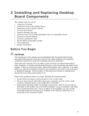
2 Installing and Replacing Desktop Board Components This chapter tells you begin installing the Desktop Board: • Always follow the steps in each procedure in the correct order. • Set up a log to record information about your computer, such as ..., or modems before you how to: • Install the I/O shield • Install and remove the Desktop Board • Install and remove system memory • Connect SATA drives • Install a Wireless LAN card • Install an Intel Z-U130 USB Solid-State Drive (or compatible device) • Connect to a metal part of the procedures...
2 Installing and Replacing Desktop Board Components This chapter tells you begin installing the Desktop Board: • Always follow the steps in each procedure in the correct order. • Set up a log to record information about your computer, such as ..., or modems before you how to: • Install the I/O shield • Install and remove the Desktop Board • Install and remove system memory • Connect SATA drives • Install a Wireless LAN card • Install an Intel Z-U130 USB Solid-State Drive (or compatible device) • Connect to a metal part of the procedures...

Product Guide
Page 29
... fit, obtain a properly-sized shield from dust and foreign objects, and promotes correct airflow within the chassis. Installing and Replacing Desktop Board Components Installing the I/O Shield The Desktop Board comes with an I /O shield before installing the Desktop Board in the chassis. When installed in Figure 4. Install the I /O shield. Press the shield into place so that it fits...
... fit, obtain a properly-sized shield from dust and foreign objects, and promotes correct airflow within the chassis. Installing and Replacing Desktop Board Components Installing the I/O Shield The Desktop Board comes with an I /O shield before installing the Desktop Board in the chassis. When installed in Figure 4. Install the I /O shield. Press the shield into place so that it fits...

Product Guide
Page 31
... 2. Installing and Replacing Desktop Board Components Installing System Memory NOTE To be fully compliant with the back edge tilted slightly upwards, insert the SO-DIMM into the retention arms. Figure 6. Installing System Memory 31 Observe the precautions in the socket. The Desktop Board has one 200-pin... DDR2 SO-DIMM socket that support the Serial Presence Detect (SPD) data structure. Hold the DIMM with all applicable Intel SDRAM memory specifications, the board requires SO-DIMMs that supports up to 2 ...
... 2. Installing and Replacing Desktop Board Components Installing System Memory NOTE To be fully compliant with the back edge tilted slightly upwards, insert the SO-DIMM into the retention arms. Figure 6. Installing System Memory 31 Observe the precautions in the socket. The Desktop Board has one 200-pin... DDR2 SO-DIMM socket that support the Serial Presence Detect (SPD) data structure. Hold the DIMM with all applicable Intel SDRAM memory specifications, the board requires SO-DIMMs that supports up to 2 ...

Product Guide
Page 33
Connecting the SATA Data and Power Cables 33 Installing and Replacing Desktop Board Components Figure 8.
Connecting the SATA Data and Power Cables 33 Installing and Replacing Desktop Board Components Figure 8.

Product Guide
Page 35
...solid state drive with the drive. Installing an Intel Z-U130 USB Solid-State Drive (or Compatible Device) 35 Figure 10. This header provides support for the solid state drive. Secure the solid state drive to the Desktop Board with the screw (Figure 10, B) included with...Observe the precautions in "Before You Begin" on the Desktop Board by using the onboard USB 2.0 header indicated in Figure 10. 3. Installing and Replacing Desktop Board Components Installing an Intel® Z-U130 USB Solid-State Drive (or Compatible Device) An Intel Z-U130 USB Solid-State Drive (or compatible device) ...
...solid state drive with the drive. Installing an Intel Z-U130 USB Solid-State Drive (or Compatible Device) 35 Figure 10. This header provides support for the solid state drive. Secure the solid state drive to the Desktop Board with the screw (Figure 10, B) included with...Observe the precautions in "Before You Begin" on the Desktop Board by using the onboard USB 2.0 header indicated in Figure 10. 3. Installing and Replacing Desktop Board Components Installing an Intel® Z-U130 USB Solid-State Drive (or Compatible Device) An Intel Z-U130 USB Solid-State Drive (or compatible device) ...
Product Guide
Page 37
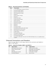
Table 6. Installing and Replacing Desktop Board Components Table 5. Serial Port Header (COM 1 and COM 2) Pin Signal Name Pin Signal Name 1 DCD (Data Carrier Detect) 3 TXD# (Transmit Data) 5 Ground 7 RTS (Request To ... PCI bus add-in card connector S/PDIF header Front panel USB header Internal mono speaker header Front panel audio header Front panel USB header with Intel Z-U130 USB Solid-State Drive (or compatible device) support Internal Connectors and Headers Table 6 through Table 21 list the signal names for the connectors and...
Table 6. Installing and Replacing Desktop Board Components Table 5. Serial Port Header (COM 1 and COM 2) Pin Signal Name Pin Signal Name 1 DCD (Data Carrier Detect) 3 TXD# (Transmit Data) 5 Ground 7 RTS (Request To ... PCI bus add-in card connector S/PDIF header Front panel USB header Internal mono speaker header Front panel audio header Front panel USB header with Intel Z-U130 USB Solid-State Drive (or compatible device) support Internal Connectors and Headers Table 6 through Table 21 list the signal names for the connectors and...
Product Guide
Page 39
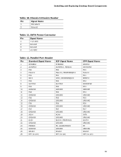
... GROUND WAIT# GROUND PE GROUND SELECT KEY (no pin) 39 SATA Power Connector Pin Signal Name 1 +12 VDC 2 Ground 3 Ground 4 +5 VDC Table 12. Installing and Replacing Desktop Board Components Table 10. Chassis Intrusion Header Pin Signal Name 1 Intruder# 2 Ground Table 11.
... GROUND WAIT# GROUND PE GROUND SELECT KEY (no pin) 39 SATA Power Connector Pin Signal Name 1 +12 VDC 2 Ground 3 Ground 4 +5 VDC Table 12. Installing and Replacing Desktop Board Components Table 10. Chassis Intrusion Header Pin Signal Name 1 Intruder# 2 Ground Table 11.

Product Guide
Page 41
... 8 9 KEY (no pin) Pin Signal Name 2 +5 VDC 4 D- 6 D+ 8 Ground 10 LED# Add-in Card Connectors The board has the following add-in boards with SMBus support to support two PCI bus master expansion cards, the riser card must support the following considerations for use of up...8226; Pin B14: additional PCI Grant signal (i.e., GNT#2) 41 In order to access sensor data on the board. Installing and Replacing Desktop Board Components Table 18. Front Panel USB Header (with Intel Z-U130 USB Solid-State Drive (or Compatible Device) Support) Pin Signal Name 1 +5 VDC 3 D- 5...
... 8 9 KEY (no pin) Pin Signal Name 2 +5 VDC 4 D- 6 D+ 8 Ground 10 LED# Add-in Card Connectors The board has the following add-in boards with SMBus support to support two PCI bus master expansion cards, the riser card must support the following considerations for use of up...8226; Pin B14: additional PCI Grant signal (i.e., GNT#2) 41 In order to access sensor data on the board. Installing and Replacing Desktop Board Components Table 18. Front Panel USB Header (with Intel Z-U130 USB Solid-State Drive (or Compatible Device) Support) Pin Signal Name 1 +5 VDC 3 D- 5...

Product Guide
Page 43
Installing and Replacing Desktop Board Components Table 21. Proper LED function requires one of the following: • A SATA hard drive connected to an onboard SATA connector • A PATA hard drive connected to an onboard PATA connector • Intel Z-U130 USB Solid State Drive (or compatible device) connected to one of the front panel USB headers... Pin Signal In/ Out Description Pin Hard Drive Activity LED 1 HD_PWR Out Hard disk LED 2 pull-up to provide a visual indicator that is closed, the board resets and runs the POST. 43
Installing and Replacing Desktop Board Components Table 21. Proper LED function requires one of the following: • A SATA hard drive connected to an onboard SATA connector • A PATA hard drive connected to an onboard PATA connector • Intel Z-U130 USB Solid State Drive (or compatible device) connected to one of the front panel USB headers... Pin Signal In/ Out Description Pin Hard Drive Activity LED 1 HD_PWR Out Hard disk LED 2 pull-up to provide a visual indicator that is closed, the board resets and runs the POST. 43

Product Guide
Page 45
Connection Diagram for the front panel USB header (see Figure 11, W). Figure 14. Installing and Replacing Desktop Board Components Figure 14 is a connection diagram for the Front Panel USB Header with Intel Z-U130 USB Solid-State Drive (or Compatible Device) Support 45
Connection Diagram for the front panel USB header (see Figure 11, W). Figure 14. Installing and Replacing Desktop Board Components Figure 14 is a connection diagram for the Front Panel USB Header with Intel Z-U130 USB Solid-State Drive (or Compatible Device) Support 45

Product Guide
Page 47
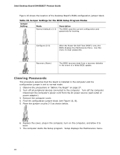
Figure 16. BIOS Configuration Jumper Block The three-pin BIOS jumper block enables board operating modes. Figure 16 shows the location of the available modes. 47 Table 23 shows the jumper settings for each of the Desktop Board's BIOS configuration jumper block. Installing and Replacing Desktop Board Components Setting the BIOS Configuration Jumper NOTE Always turn off the power and unplug the power cord from the computer before changing a jumper. Moving the jumper with the power on may result in unreliable computer operation.
Figure 16. BIOS Configuration Jumper Block The three-pin BIOS jumper block enables board operating modes. Figure 16 shows the location of the available modes. 47 Table 23 shows the jumper settings for each of the Desktop Board's BIOS configuration jumper block. Installing and Replacing Desktop Board Components Setting the BIOS Configuration Jumper NOTE Always turn off the power and unplug the power cord from the computer before changing a jumper. Moving the jumper with the power on may result in unreliable computer operation.
Product Guide
Page 48
...normal mode. 1. Turn off the computer. Turn off all peripheral devices connected to boot. 7. Remove the computer cover. 4. Replace the cover, plug in the computer and the configuration jumper is set to clear passwords. Table 23. Configure (2-3) After the ... passwords for booting. Clearing Passwords This procedure assumes that the board is installed in the computer, turn on page 27. 2. Observe the precautions in the event of the Desktop Board's BIOS configuration jumper block. Intel Desktop Board D945GSEJT Product Guide Figure 16 shows the location of a failed BIOS...
...normal mode. 1. Turn off the computer. Turn off all peripheral devices connected to boot. 7. Remove the computer cover. 4. Replace the cover, plug in the computer and the configuration jumper is set to clear passwords. Table 23. Configure (2-3) After the ... passwords for booting. Clearing Passwords This procedure assumes that the board is installed in the computer, turn on page 27. 2. Observe the precautions in the event of the Desktop Board's BIOS configuration jumper block. Intel Desktop Board D945GSEJT Product Guide Figure 16 shows the location of a failed BIOS...

Product Guide
Page 49
Use the arrow keys to save the current values and exit Setup. 10. Replacing the Battery A coin-cell battery powers the Desktop Board's real-time clock and CMOS memory. Batteries should be accurate. Disposal of three years. OBS! Installing and Replacing Desktop Board Components 8. Setup displays the maintenance menu again. 9. Turn off the computer. Remove the computer...
Use the arrow keys to save the current values and exit Setup. 10. Replacing the Battery A coin-cell battery powers the Desktop Board's real-time clock and CMOS memory. Batteries should be accurate. Disposal of three years. OBS! Installing and Replacing Desktop Board Components 8. Setup displays the maintenance menu again. 9. Turn off the computer. Remove the computer...

Product Guide
Page 53
...cover. 4. Disconnect the battery cable from the board. Connect the cable on the battery (Figure 17, B) and carefully remove it from the Desktop Board battery connector (Figure 17, A). 6. Turn off all peripheral devices connected to the board with a non-permanent adhesive pad. 7. ... up on the new battery to the Desktop Board battery connector and reattach the battery to the board. 8. It is attached to the computer. Figure 17. Installing and Replacing Desktop Board Components To replace the battery, follow these steps: 1. Replace the computer cover. Disconnect the computer's ...
...cover. 4. Disconnect the battery cable from the board. Connect the cable on the battery (Figure 17, B) and carefully remove it from the Desktop Board battery connector (Figure 17, A). 6. Turn off all peripheral devices connected to the board with a non-permanent adhesive pad. 7. ... up on the new battery to the Desktop Board battery connector and reattach the battery to the board. 8. It is attached to the computer. Figure 17. Installing and Replacing Desktop Board Components To replace the battery, follow these steps: 1. Replace the computer cover. Disconnect the computer's ...

Product Guide
Page 61
...Conformity statement • Product Ecology statements • Electromagnetic Compatibility (EMC) regulations • Product certifications Safety Standards Intel Desktop Board D945GSEJT complies with the safety standards stated in Table 27 when correctly installed in accordance with local environmental regulations. Part... should be permanently and legibly marked on this Desktop Board to provide instructions for Intel Desktop Board D945GSEJT: • Safety standards • European Union Declaration of explosion if the battery is replaced with Intel Desktop Board D945GSEJT.
...Conformity statement • Product Ecology statements • Electromagnetic Compatibility (EMC) regulations • Product certifications Safety Standards Intel Desktop Board D945GSEJT complies with the safety standards stated in Table 27 when correctly installed in accordance with local environmental regulations. Part... should be permanently and legibly marked on this Desktop Board to provide instructions for Intel Desktop Board D945GSEJT: • Safety standards • European Union Declaration of explosion if the battery is replaced with Intel Desktop Board D945GSEJT.


