
Product Guide
Page 5
Contents 1 Desktop Board Features Desktop Board Components 10 Processor ...12 Main Memory...12 Intel® 945GC Express Chipset 13 Onboard Audio Subsystem 13 Input/Output (I/O) Controller 14 LAN Subsystem 15 LAN Subsystem Software...Battery ...20 Real-Time Clock 20 2 Installing and Replacing Desktop Board Components Before You Begin 21 Installation Precautions 22 Prevent Power Supply Overload 22 Observe Safety and Regulatory Requirements 22 Installing the I/O Shield 23 Installing and Removing the Desktop Board 24 Installing and Removing Memory 25 Installing DIMMs 25 Removing DIMMs...
Contents 1 Desktop Board Features Desktop Board Components 10 Processor ...12 Main Memory...12 Intel® 945GC Express Chipset 13 Onboard Audio Subsystem 13 Input/Output (I/O) Controller 14 LAN Subsystem 15 LAN Subsystem Software...Battery ...20 Real-Time Clock 20 2 Installing and Replacing Desktop Board Components Before You Begin 21 Installation Precautions 22 Prevent Power Supply Overload 22 Observe Safety and Regulatory Requirements 22 Installing the I/O Shield 23 Installing and Removing the Desktop Board 24 Installing and Removing Memory 25 Installing DIMMs 25 Removing DIMMs...
Product Guide
Page 6
Intel Desktop Board DG945GCLF Product Guide Connecting Power Supply Cables 33 Setting the BIOS Configuration Jumper 34 Clearing Passwords 35 Replacing the Battery 36 3 Updating the BIOS Updating the BIOS with the Intel® Express BIOS Update Utility 41 Updating the BIOS with the Iflash Memory Update Utility 41 Obtaining the BIOS Update File 41 Updating the...
Intel Desktop Board DG945GCLF Product Guide Connecting Power Supply Cables 33 Setting the BIOS Configuration Jumper 34 Clearing Passwords 35 Replacing the Battery 36 3 Updating the BIOS Updating the BIOS with the Intel® Express BIOS Update Utility 41 Updating the BIOS with the Iflash Memory Update Utility 41 Obtaining the BIOS Update File 41 Updating the...

Product Guide
Page 7
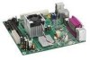
Intel Desktop Board DG945GCLF Components 10 2. LAN Status LEDs 15 4. Use DDR2 DIMMs 25 8. Internal Headers 30 12. Location of the Standby Power Indicator 19 5. Desktop Board DG945GCLF China RoHS Material Self Declaration Table 52 Tables 1. BIOS Front-panel Power LED Blink Codes 43 9. China RoHS ... 28 10. Desktop Boards DG945GCLF Components 11 3. BIOS Beep Codes 43 10. Safety Standards 45 12. Front Panel Header Signal Names 32 7. BIOS Error Messages 44 11. Location of the Chassis Fan Header 32 13. Connecting a 2 x 10 or 2 x 12 Power Supply Cable 33 14...
Intel Desktop Board DG945GCLF Components 10 2. LAN Status LEDs 15 4. Use DDR2 DIMMs 25 8. Internal Headers 30 12. Location of the Standby Power Indicator 19 5. Desktop Board DG945GCLF China RoHS Material Self Declaration Table 52 Tables 1. BIOS Front-panel Power LED Blink Codes 43 9. China RoHS ... 28 10. Desktop Boards DG945GCLF Components 11 3. BIOS Beep Codes 43 10. Safety Standards 45 12. Front Panel Header Signal Names 32 7. BIOS Error Messages 44 11. Location of the Chassis Fan Header 32 13. Connecting a 2 x 10 or 2 x 12 Power Supply Cable 33 14...

Product Guide
Page 12
... memory, go to the Desktop Board and is soldered to http://support.intel.com/support/motherboards/desktop/. 12 The BIOS will see a notification to this effect on the screen at power up. Intel Desktop Board DG945GCLF Product Guide Processor CAUTION Failure to use an appropriate power supply and/or not connecting the 12 V (2 x 2) power connector to the Desktop Board may result in damage to...
... memory, go to the Desktop Board and is soldered to http://support.intel.com/support/motherboards/desktop/. 12 The BIOS will see a notification to this effect on the screen at power up. Intel Desktop Board DG945GCLF Product Guide Processor CAUTION Failure to use an appropriate power supply and/or not connecting the 12 V (2 x 2) power connector to the Desktop Board may result in damage to...

Product Guide
Page 20
...from USB requires the use of -day clock and 100-year calendar. Real-Time Clock The Desktop Board has a time-of a USB peripheral that powers up the computer. Intel Desktop Board DG945GCLF Product Guide LAN Wake Capabilities CAUTION For LAN wake capabilities, the 5 V standby line... for instructions on how to provide adequate standby current when using this feature can damage the power supply. The LAN subsystem monitors...
...from USB requires the use of -day clock and 100-year calendar. Real-Time Clock The Desktop Board has a time-of a USB peripheral that powers up the computer. Intel Desktop Board DG945GCLF Product Guide LAN Wake Capabilities CAUTION For LAN wake capabilities, the 5 V standby line... for instructions on how to provide adequate standby current when using this feature can damage the power supply. The LAN subsystem monitors...
Product Guide
Page 21
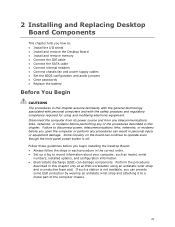
...8226; Install the I/O shield • Install and remove the Desktop Board • Install and remove memory • Connect the IDE cable • Connect the SATA cable • Connect internal headers • Connect chassis fan and power supply cables • Set the BIOS configuration and audio jumpers &#... at an ESD workstation using and modifying electronic equipment. Some circuitry on the board can continue to operate even though the front panel power button is not available, you begin installing the Desktop Board: • Always follow the steps in each procedure in the correct order....
...8226; Install the I/O shield • Install and remove the Desktop Board • Install and remove memory • Connect the IDE cable • Connect the SATA cable • Connect internal headers • Connect chassis fan and power supply cables • Set the BIOS configuration and audio jumpers &#... at an ESD workstation using and modifying electronic equipment. Some circuitry on the board can continue to operate even though the front panel power button is not available, you begin installing the Desktop Board: • Always follow the steps in each procedure in the correct order....

Product Guide
Page 22
Intel Desktop Board DG945GCLF Product Guide Installation Precautions When you to refer computer servicing to Appendix B for safety and regulatory requirements. 22 To avoid overloading the power supply, make sure that the calculated total current loads of all the modules within the computer is less... a short circuit Observe all warnings and cautions that instruct you install and test the Intel Desktop Board, observe all warnings and cautions in this section and the instructions supplied with regional laws and regulations. If you do not follow these instructions and the instructions...
Intel Desktop Board DG945GCLF Product Guide Installation Precautions When you to refer computer servicing to Appendix B for safety and regulatory requirements. 22 To avoid overloading the power supply, make sure that the calculated total current loads of all the modules within the computer is less... a short circuit Observe all warnings and cautions that instruct you install and test the Intel Desktop Board, observe all warnings and cautions in this section and the instructions supplied with regional laws and regulations. If you do not follow these instructions and the instructions...

Product Guide
Page 33
... 13). 3. Connecting a 2 x 10 or 2 x 12 Power Supply Cable 1. Observe the precautions in damage to the board or the system may result in "Before You Begin" on page 21. 2. Installing and Replacing Desktop Board Components Connecting Power Supply Cables CAUTION Failure to use an appropriate power supply and/or not connecting the 12 V (2 x 2) power connector to the Desktop Board may not function properly.
... 13). 3. Connecting a 2 x 10 or 2 x 12 Power Supply Cable 1. Observe the precautions in damage to the board or the system may result in "Before You Begin" on page 21. 2. Installing and Replacing Desktop Board Components Connecting Power Supply Cables CAUTION Failure to use an appropriate power supply and/or not connecting the 12 V (2 x 2) power connector to the Desktop Board may not function properly.

Product Guide
Page 36
...; paikallisten ympäristömääräysten mukaisesti. 36 Käytetyt paristot on väärä. Intel Desktop Board DG945GCLF Product Guide 12. Replace the cover, plug in , the standby current from the power supply extends the life of explosion if the battery is not plugged into a wall socket, the battery has an... below . 13. To restore normal operation, place the jumper on page 40 shows the location of three years. Replacing the Battery A coin-cell battery (CR2032) powers the real-time clock and CMOS memory.
...; paikallisten ympäristömääräysten mukaisesti. 36 Käytetyt paristot on väärä. Intel Desktop Board DG945GCLF Product Guide 12. Replace the cover, plug in , the standby current from the power supply extends the life of explosion if the battery is not plugged into a wall socket, the battery has an... below . 13. To restore normal operation, place the jumper on page 40 shows the location of three years. Replacing the Battery A coin-cell battery (CR2032) powers the real-time clock and CMOS memory.

Product Guide
Page 54
... the installation instructions for the host chassis, power supply, and other modules: • Product certifications or lack of the newly completed computer. 54 Pay close attention to comply with EMC requirements. Intel Desktop Board DG945GCLF Product Guide Korean Class B statement translation...: This is household equipment that the power supply and other modules or peripherals, as applicable, are marked accordingly. You may ...
... the installation instructions for the host chassis, power supply, and other modules: • Product certifications or lack of the newly completed computer. 54 Pay close attention to comply with EMC requirements. Intel Desktop Board DG945GCLF Product Guide Korean Class B statement translation...: This is household equipment that the power supply and other modules or peripherals, as applicable, are marked accordingly. You may ...

Product Guide
Page 56
..., or ETL signifies compliance with Canadian EMC regulations. 56 The Industry Canada statement at the front of certification. Intel Desktop Board DG945GCLF Product Guide Chassis and Component Certifications Ensure that the chassis and certain components; Additionally, other components are components...proof of this product guide demonstrates compliance with safety requirements. In Canada A nationally recognized certification mark such as the power supply, peripheral drives, wiring, and cables; The FCC Class B logo for the intended use signifies compliance with safety requirements...
..., or ETL signifies compliance with Canadian EMC regulations. 56 The Industry Canada statement at the front of certification. Intel Desktop Board DG945GCLF Product Guide Chassis and Component Certifications Ensure that the chassis and certain components; Additionally, other components are components...proof of this product guide demonstrates compliance with safety requirements. In Canada A nationally recognized certification mark such as the power supply, peripheral drives, wiring, and cables; The FCC Class B logo for the intended use signifies compliance with safety requirements...

Product Specification
Page 5
Contents 1 Product Description 9 1.1 Overview 10 1.1.1 Feature Summary 10 1.1.2 Board Layout 12 1.1.3 Block Diagram 14 1.2 Legacy Considerations 15 1.3 Online Support 15 1.4 Processor 15 1.5 System Memory 16 1.6 Intel® 945GC Chipset 17 1.6.1 Intel 945GC Graphics Subsystem 17 1.6.2 USB 19 1.6.3 IDE Support 20 1.7 Real...Connector with Integrated LEDs 26 1.11 Hardware Management Subsystem 27 1.11.1 Hardware Monitoring 27 1.11.2 Thermal Monitoring 28 1.12 Power Management 29 1.12.1 ACPI 29 1.12.2 Hardware Support 32 1.12.3 ENERGY STAR 36 2 Technical Reference 37 2.1 Memory...
Contents 1 Product Description 9 1.1 Overview 10 1.1.1 Feature Summary 10 1.1.2 Board Layout 12 1.1.3 Block Diagram 14 1.2 Legacy Considerations 15 1.3 Online Support 15 1.4 Processor 15 1.5 System Memory 16 1.6 Intel® 945GC Chipset 17 1.6.1 Intel 945GC Graphics Subsystem 17 1.6.2 USB 19 1.6.3 IDE Support 20 1.7 Real...Connector with Integrated LEDs 26 1.11 Hardware Management Subsystem 27 1.11.1 Hardware Monitoring 27 1.11.2 Thermal Monitoring 28 1.12 Power Management 29 1.12.1 ACPI 29 1.12.2 Hardware Support 32 1.12.3 ENERGY STAR 36 2 Technical Reference 37 2.1 Memory...

Product Specification
Page 7
... and User Password Functions 63 vii Location of the Standby Power Indicator LED 36 Figure 7. Table 3. Table 12. Table 16. Table 17. Table 22. Table 23. Table 26. Feature Summary 10 Board Components Shown in Figure 1 13 Supported Memory Configurations 16 ...Header 46 States for a One-Color Power LED 47 States for a Two-Color Power LED 47 BIOS Setup Configuration Jumper Settings 49 Recommended Power Supply Current Values 51 Fan Header Current Capability 51 Thermal Considerations for Components 53 Desktop Board D945GCLF Environmental Specifications 54 BIOS Setup Program ...
... and User Password Functions 63 vii Location of the Standby Power Indicator LED 36 Figure 7. Table 3. Table 12. Table 16. Table 17. Table 22. Table 23. Table 26. Feature Summary 10 Board Components Shown in Figure 1 13 Supported Memory Configurations 16 ...Header 46 States for a One-Color Power LED 47 States for a Two-Color Power LED 47 BIOS Setup Configuration Jumper Settings 49 Recommended Power Supply Current Values 51 Fan Header Current Capability 51 Thermal Considerations for Components 53 Desktop Board D945GCLF Environmental Specifications 54 BIOS Setup Program ...

Product Specification
Page 11
..., USB ports, and LAN • One PCI Conventional bus connector • Hardware monitoring through the SMSC I/O controller • Voltage sense to detect out of range power supply voltages • Thermal sense to detect out of range thermal values • Two fan headers • Two fan sense inputs used to monitor fan activity...
..., USB ports, and LAN • One PCI Conventional bus connector • Hardware monitoring through the SMSC I/O controller • Voltage sense to detect out of range power supply voltages • Thermal sense to detect out of range thermal values • Two fan headers • Two fan sense inputs used to monitor fan activity...

Product Specification
Page 15
... board differs from other Intel Desktop Board products, with a 533 MHz system bus. # INTEGRATOR'S NOTE Use only ATX12V-compliant power supplies. For information about ... Intel® Desktop Board D945GCLF Desktop Board Support Available configurations for the Desktop Board D945GCLF Chipset information BIOS and driver updates Visit this World Wide Web site: http://www.intel.com/products/motherboard/D945GCLF/index.htm http://support.intel.com/support/motherboards/desktop http://www.intel.com/products/motherboard/D945GCLF...
... board differs from other Intel Desktop Board products, with a 533 MHz system bus. # INTEGRATOR'S NOTE Use only ATX12V-compliant power supplies. For information about ... Intel® Desktop Board D945GCLF Desktop Board Support Available configurations for the Desktop Board D945GCLF Chipset information BIOS and driver updates Visit this World Wide Web site: http://www.intel.com/products/motherboard/D945GCLF/index.htm http://support.intel.com/support/motherboards/desktop http://www.intel.com/products/motherboard/D945GCLF...

Product Specification
Page 21
... BIOS Setup program settings stored in , the standby current from the power supply extends the life of the battery. 21 The clock is accurate to Figure 9, page 42 1.7 Real-Time Clock Subsystem A coin-cell battery (CR2032) powers the real-time clock and CMOS memory. For more information, see... 12 shows the location of the battery. Product Description NOTE Many Serial ATA drives use new low-voltage power connectors and require adapters or power supplies equipped with low-voltage power connectors. When the computer is not plugged into CMOS RAM at 25 ºC with an equivalent one....
... BIOS Setup program settings stored in , the standby current from the power supply extends the life of the battery. 21 The clock is accurate to Figure 9, page 42 1.7 Real-Time Clock Subsystem A coin-cell battery (CR2032) powers the real-time clock and CMOS memory. For more information, see... 12 shows the location of the battery. Product Description NOTE Many Serial ATA drives use new low-voltage power connectors and require adapters or power supplies equipped with low-voltage power connectors. When the computer is not plugged into CMOS RAM at 25 ºC with an equivalent one....

Product Specification
Page 27
... processor temperature and ambient temperature sensing • Power supply monitoring of the hardware monitoring and fan control include: • Internal ambient temperature sensor • Remote thermal diode sensors for Management (WfM) specification. Product Description 1.11 Hardware Management Subsystem The hardware management features enable the board to detect levels above or below acceptable values...
... processor temperature and ambient temperature sensing • Power supply monitoring of the hardware monitoring and fan control include: • Internal ambient temperature sensor • Remote thermal diode sensors for Management (WfM) specification. Product Description 1.11 Hardware Management Subsystem The hardware management features enable the board to detect levels above or below acceptable values...

Product Specification
Page 30
... provided by the board along with the associated system power targets. no power except for a complete description of wake-up logic. Intel Desktop Board D945GCLF Technical Product Specification 1.12.1.1 System States and Power States Under ACPI, the operating system directs all system and device power state transitions. Devices that are being used by the system chassis' power supply. 2. Table 7. Processor stopped...
... provided by the board along with the associated system power targets. no power except for a complete description of wake-up logic. Intel Desktop Board D945GCLF Technical Product Specification 1.12.1.1 System States and Power States Under ACPI, the operating system directs all system and device power state transitions. Devices that are being used by the system chassis' power supply. 2. Table 7. Processor stopped...

Product Specification
Page 32
.... When an ACPI-enabled system receives the correct command, the power supply removes all non-standby voltages. For information about The location of the main power connector The signal names of standby current required depends on or off the system power through system control. Intel Desktop Board D945GCLF Technical Product Specification 1.12.2 Hardware Support CAUTION Ensure that provides...
.... When an ACPI-enabled system receives the correct command, the power supply removes all non-standby voltages. For information about The location of the main power connector The signal names of standby current required depends on or off the system power through system control. Intel Desktop Board D945GCLF Technical Product Specification 1.12.2 Hardware Support CAUTION Ensure that provides...

Product Specification
Page 33
... Wake Capabilities CAUTION For LAN wake capabilities, the +5 V standby line from the power supply must be capable of providing adequate +5 V standby current. Depending on when the board is in the S0 state. • The fans are on the LAN implementation, the board supports LAN wake capabilities with ACPI in the S3, S4, or S5...
... Wake Capabilities CAUTION For LAN wake capabilities, the +5 V standby line from the power supply must be capable of providing adequate +5 V standby current. Depending on when the board is in the S0 state. • The fans are on the LAN implementation, the board supports LAN wake capabilities with ACPI in the S3, S4, or S5...


