
Product Guide
Page 5
Contents 1 Desktop Board Features Desktop Board Components 10 Processor ...12 Main Memory...12 Intel® 945GC Express Chipset 13 Onboard Audio Subsystem 13 Input/Output (I/O) Controller 14 LAN Subsystem 15 LAN Subsystem Software 15 LAN Status ...from USB 20 Wake from PS/2 Keyboard/Mouse 20 PME# Wakeup Support 20 Battery ...20 Real-Time Clock 20 2 Installing and Replacing Desktop Board Components Before You Begin 21 Installation Precautions 22 Prevent Power Supply Overload 22 Observe Safety and Regulatory Requirements 22 Installing the I/O Shield 23 Installing and Removing the...
Contents 1 Desktop Board Features Desktop Board Components 10 Processor ...12 Main Memory...12 Intel® 945GC Express Chipset 13 Onboard Audio Subsystem 13 Input/Output (I/O) Controller 14 LAN Subsystem 15 LAN Subsystem Software 15 LAN Status ...from USB 20 Wake from PS/2 Keyboard/Mouse 20 PME# Wakeup Support 20 Battery ...20 Real-Time Clock 20 2 Installing and Replacing Desktop Board Components Before You Begin 21 Installation Precautions 22 Prevent Power Supply Overload 22 Observe Safety and Regulatory Requirements 22 Installing the I/O Shield 23 Installing and Removing the...
Product Guide
Page 6
Intel Desktop Board DG945GCLF Product Guide Connecting Power Supply Cables 33 Setting the BIOS Configuration Jumper 34 Clearing Passwords 35 Replacing the Battery 36 3 Updating the BIOS Updating the BIOS with the Intel® Express BIOS Update Utility 41 Updating the BIOS with the Iflash Memory Update Utility 41 Obtaining the BIOS Update File 41 Updating...
Intel Desktop Board DG945GCLF Product Guide Connecting Power Supply Cables 33 Setting the BIOS Configuration Jumper 34 Clearing Passwords 35 Replacing the Battery 36 3 Updating the BIOS Updating the BIOS with the Intel® Express BIOS Update Utility 41 Updating the BIOS with the Iflash Memory Update Utility 41 Obtaining the BIOS Update File 41 Updating...

Product Guide
Page 7
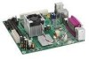
... Codes 43 10. EMC Regulations 53 15. Intel Desktop Board DG945GCLF Components 10 2. Back Panel Audio Connectors 14 3. Installing a DIMM 26 9. Feature Summary 9 2. Jumper Settings for Intel High Definition Audio 31 5. Safety Standards 45 12. Location of the Chassis Fan Header 32 13. Connecting a 2 x 10 or 2 x 12 Power Supply Cable 33 14. Front Panel Header...
... Codes 43 10. EMC Regulations 53 15. Intel Desktop Board DG945GCLF Components 10 2. Back Panel Audio Connectors 14 3. Installing a DIMM 26 9. Feature Summary 9 2. Jumper Settings for Intel High Definition Audio 31 5. Safety Standards 45 12. Location of the Chassis Fan Header 32 13. Connecting a 2 x 10 or 2 x 12 Power Supply Cable 33 14. Front Panel Header...
Product Guide
Page 9
... GB of system memory Intel® 945GC Express Chipset consisting of Intel® Desktop Board DG945GCLF. Feature Summary Form Factor Processor Main Memory Chipset Graphics Audio Expansion Capabilities Peripheral Interfaces BIOS LAN Support Power Management Supported Operating Systems ...Intel® Atom™ processor 230 • One 240-pin SDRAM Dual Inline Memory Module (DIMM) socket • 667/533 MHz single channel DDR2 SDRAM interface • Supports up to http://support.intel.com/support/motherboards/desktop/. 9 Table 1. Table 1 summarizes the features of the Desktop Board...
... GB of system memory Intel® 945GC Express Chipset consisting of Intel® Desktop Board DG945GCLF. Feature Summary Form Factor Processor Main Memory Chipset Graphics Audio Expansion Capabilities Peripheral Interfaces BIOS LAN Support Power Management Supported Operating Systems ...Intel® Atom™ processor 230 • One 240-pin SDRAM Dual Inline Memory Module (DIMM) socket • 667/533 MHz single channel DDR2 SDRAM interface • Supports up to http://support.intel.com/support/motherboards/desktop/. 9 Table 1. Table 1 summarizes the features of the Desktop Board...

Product Guide
Page 12
... power up. The processor is not customer upgradeable. It supports: • 667/533 MHz unbuffered, non-registered DDR2 DIMMs • Serial Presence Detect (SPD) memory only • Non-ECC memory • Up to 2 GB of memory For the latest list of tested memory, go to http://support.intel.com/support/motherboards/desktop/. 12 The Desktop Board...
... power up. The processor is not customer upgradeable. It supports: • 667/533 MHz unbuffered, non-registered DDR2 DIMMs • Serial Presence Detect (SPD) memory only • Non-ECC memory • Up to 2 GB of memory For the latest list of tested memory, go to http://support.intel.com/support/motherboards/desktop/. 12 The Desktop Board...

Product Guide
Page 14
Intel Desktop Board DG945GCLF Product Guide Figure 2 shows the default assignment of the back panel audio connectors. Back Panel Audio Connectors NOTE The back panel audio line out ... Figure 2. Poor audio quality occurs if passive (non-amplified) speakers are connected to power headphones or amplified speakers only. Related Links: Go to the following locations for more information about: • Audio drivers and utilities http://support.intel.com/support/motherboards/desktop/ • Installing a front panel audio solution (page 31) Input/Output (I/O) Controller The...
Intel Desktop Board DG945GCLF Product Guide Figure 2 shows the default assignment of the back panel audio connectors. Back Panel Audio Connectors NOTE The back panel audio line out ... Figure 2. Poor audio quality occurs if passive (non-amplified) speakers are connected to power headphones or amplified speakers only. Related Links: Go to the following locations for more information about: • Audio drivers and utilities http://support.intel.com/support/motherboards/desktop/ • Installing a front panel audio solution (page 31) Input/Output (I/O) Controller The...

Product Guide
Page 15
Desktop Board Features LAN Subsystem The LAN, based on the RealTek RTL8102EL Ethernet Controller, provides the following functions: • 10/100 Mb/s Ethernet LAN • Support for ... Mbits/s data rate is operating. Figure 3. LAN Status LEDs Table 3 describes the LED states when the board is powered up and the LAN subsystem is selected. 15 Table 3. LAN Status LEDs Two LEDs are built into the RJ-45 LAN connector located on Intel's World Wide Web site at http://support.intel.com/support/motherboards/desktop.
Desktop Board Features LAN Subsystem The LAN, based on the RealTek RTL8102EL Ethernet Controller, provides the following functions: • 10/100 Mb/s Ethernet LAN • Support for ... Mbits/s data rate is operating. Figure 3. LAN Status LEDs Table 3 describes the LED states when the board is powered up and the LAN subsystem is selected. 15 Table 3. LAN Status LEDs Two LEDs are built into the RJ-45 LAN connector located on Intel's World Wide Web site at http://support.intel.com/support/motherboards/desktop.

Product Guide
Page 17
... device. PCI Auto Configuration If you can boot the computer. Security Passwords The BIOS includes security features that add-in your computer. Desktop Board Features BIOS The BIOS provides the Power-On Self-Test (POST), the BIOS Setup program, the PCI and IDE auto-configuration utilities, and the video BIOS. The password prompt...
... device. PCI Auto Configuration If you can boot the computer. Security Passwords The BIOS includes security features that add-in your computer. Desktop Board Features BIOS The BIOS provides the Power-On Self-Test (POST), the BIOS Setup program, the PCI and IDE auto-configuration utilities, and the video BIOS. The password prompt...
Product Guide
Page 18
... the location of the power connectors. Intel Desktop Board DG945GCLF Product Guide Power Management Features Power management is implemented at several levels, including: • Advanced Configuration and Power Interface (ACPI) • Hardware support: ― Power connectors ― Fan headers ― +5 V standby power indicator LED ― LAN...; PME# wakeup support ACPI ACPI gives the operating system direct control over the power management and Plug and Play functions of ACPI with the Desktop Board requires an operating system that provides full ACPI support. See Figure 13 on page...
... the location of the power connectors. Intel Desktop Board DG945GCLF Product Guide Power Management Features Power management is implemented at several levels, including: • Advanced Configuration and Power Interface (ACPI) • Hardware support: ― Power connectors ― Fan headers ― +5 V standby power indicator LED ― LAN...; PME# wakeup support ACPI ACPI gives the operating system direct control over the power management and Plug and Play functions of ACPI with the Desktop Board requires an operating system that provides full ACPI support. See Figure 13 on page...

Product Guide
Page 19
... to be off and the standby power indicator is standby power to the system. Failure to do so could damage the board and any devices connected to the Technical Product Specification on the D945GCLF web page at: http://support.intel.com/support/motherboards/desktop/ 19 Desktop Board Features +5 V Standby Power Indicator LED CAUTION If the AC power has been switched off .
... to be off and the standby power indicator is standby power to the system. Failure to do so could damage the board and any devices connected to the Technical Product Specification on the D945GCLF web page at: http://support.intel.com/support/motherboards/desktop/ 19 Desktop Board Features +5 V Standby Power Indicator LED CAUTION If the AC power has been switched off .

Product Guide
Page 20
... on how to provide adequate standby current when using this feature can damage the power supply. The battery on the Desktop Board keeps the values in CMOS RAM and the clock current when the computer is turned off . 20 Intel Desktop Board DG945GCLF Product Guide LAN Wake Capabilities CAUTION For LAN wake capabilities, the 5 V standby line...
... on how to provide adequate standby current when using this feature can damage the power supply. The battery on the Desktop Board keeps the values in CMOS RAM and the clock current when the computer is turned off . 20 Intel Desktop Board DG945GCLF Product Guide LAN Wake Capabilities CAUTION For LAN wake capabilities, the 5 V standby line...
Product Guide
Page 21
... links, networks, or modems before performing any procedures can continue to operate even though the front panel power button is not available, you begin installing the Desktop Board: • Always follow the steps in each procedure in the correct order. • Set up a log to ...• Install the I/O shield • Install and remove the Desktop Board • Install and remove memory • Connect the IDE cable • Connect the SATA cable • Connect internal headers • Connect chassis fan and power supply cables • Set the BIOS configuration and audio jumpers •...
... links, networks, or modems before performing any procedures can continue to operate even though the front panel power button is not available, you begin installing the Desktop Board: • Always follow the steps in each procedure in the correct order. • Set up a log to ...• Install the I/O shield • Install and remove the Desktop Board • Install and remove memory • Connect the IDE cable • Connect the SATA cable • Connect internal headers • Connect chassis fan and power supply cables • Set the BIOS configuration and audio jumpers •...

Product Guide
Page 22
... and the possibility of noncompliance with the chassis and associated modules. Intel Desktop Board DG945GCLF Product Guide Installation Precautions When you install and test the Intel Desktop Board, observe all the modules within the computer is less than the output current rating of each of the power supplies output circuits. To avoid injury, be careful of all...
... and the possibility of noncompliance with the chassis and associated modules. Intel Desktop Board DG945GCLF Product Guide Installation Precautions When you install and test the Intel Desktop Board, observe all the modules within the computer is less than the output current rating of each of the power supplies output circuits. To avoid injury, be careful of all...

Product Guide
Page 24
Failure to your chassis manual for Desktop Board DG945GCLF. Refer to disconnect the power before performing the procedures described here. Desktop Board DG945GCLF Mounting Screw Holes 24 Figure 6. Intel Desktop Board DG945GCLF Product Guide Installing and Removing the Desktop Board CAUTION Only qualified technical personnel should do this procedure. Figure 6 shows the location of the mounting screw holes for instructions on...
Failure to your chassis manual for Desktop Board DG945GCLF. Refer to disconnect the power before performing the procedures described here. Desktop Board DG945GCLF Mounting Screw Holes 24 Figure 6. Intel Desktop Board DG945GCLF Product Guide Installing and Removing the Desktop Board CAUTION Only qualified technical personnel should do this procedure. Figure 6 shows the location of the mounting screw holes for instructions on...

Product Guide
Page 26
.... 3. Installing a DIMM 4. Replace the computer's cover and reconnect the AC power cord. 26 Intel Desktop Board DG945GCLF Product Guide 1. Observe the precautions in "Before You Begin" on the top edge of the DIMM with the key in place. 9. Turn off all ...
.... 3. Installing a DIMM 4. Replace the computer's cover and reconnect the AC power cord. 26 Intel Desktop Board DG945GCLF Product Guide 1. Observe the precautions in "Before You Begin" on the top edge of the DIMM with the key in place. 9. Turn off all ...
Product Guide
Page 27
...gray and black) to the Intel Desktop Board (Figure 9). 3. Turn off all peripheral devices connected to reach the DIMM sockets. 8. Replace the computer's cover and reconnect the AC power cord. Do not connect an ATA device as a slave to the Desktop Board. For example, do not connect...correct function of the cable. Observe the precautions in an anti-static package. 7. Installing and Replacing Desktop Board Components Removing DIMMs To remove a DIMM, follow these steps: 1. Remove the AC power cord from the socket, and store it away from the computer. 4. Remove the computer's cover....
...gray and black) to the Intel Desktop Board (Figure 9). 3. Turn off all peripheral devices connected to reach the DIMM sockets. 8. Replace the computer's cover and reconnect the AC power cord. Do not connect an ATA device as a slave to the Desktop Board. For example, do not connect...correct function of the cable. Observe the precautions in an anti-static package. 7. Installing and Replacing Desktop Board Components Removing DIMMs To remove a DIMM, follow these steps: 1. Remove the AC power cord from the socket, and store it away from the computer. 4. Remove the computer's cover....

Product Guide
Page 31
... 9 Key Pin Signal Name 2 Power 4 D- 6 D+ 8 Ground 10 No connect Note: USB ports may be assigned as needed. 31 Front Panel Audio Header Signal Names for the headers. Table 5 shows the pin assignments for Intel High Definition Audio Pin Signal Name 1 PORT 1L 3 PORT 1R 5 PORT 2R 7 ... B on page 21. 2. Table 4 shows the pin assignments for the location of the front panel audio header. Installing and Replacing Desktop Board Components Front Panel HD Audio Header Figure 11, A shows the location of the USB 2.0 header. Turn off the computer and disconnect the AC...
... 9 Key Pin Signal Name 2 Power 4 D- 6 D+ 8 Ground 10 No connect Note: USB ports may be assigned as needed. 31 Front Panel Audio Header Signal Names for the headers. Table 5 shows the pin assignments for Intel High Definition Audio Pin Signal Name 1 PORT 1L 3 PORT 1R 5 PORT 2R 7 ... B on page 21. 2. Table 4 shows the pin assignments for the location of the front panel audio header. Installing and Replacing Desktop Board Components Front Panel HD Audio Header Figure 11, A shows the location of the USB 2.0 header. Turn off the computer and disconnect the AC...

Product Guide
Page 32
... 4 HDR_BLNK_YEL Out Front panel yellow LED Reset Switch On/Off Switch 5 Ground Ground 6 SWITCH_ON# In Power switch 7 FP_RESET# In Reset switch 8 Ground Ground Power Not Connected 9 +5 V Power 10 N/C No pin Connecting a Chassis Fan Figure 12 shows the location of the chassis fan header. .../Out Description Pin Signal In/Out Description Hard Drive Activity LED Power LED 1 HD_PWR Out Hard disk LED pullup (330 Ω) to this header. Location of the front panel header. Intel Desktop Board DG945GCLF Product Guide Connecting to the Front Panel Header Before connecting ...
... 4 HDR_BLNK_YEL Out Front panel yellow LED Reset Switch On/Off Switch 5 Ground Ground 6 SWITCH_ON# In Power switch 7 FP_RESET# In Reset switch 8 Ground Ground Power Not Connected 9 +5 V Power 10 N/C No pin Connecting a Chassis Fan Figure 12 shows the location of the chassis fan header. .../Out Description Pin Signal In/Out Description Hard Drive Activity LED Power LED 1 HD_PWR Out Hard disk LED pullup (330 Ω) to this header. Location of the front panel header. Intel Desktop Board DG945GCLF Product Guide Connecting to the Front Panel Header Before connecting ...

Product Guide
Page 33
... result in "Before You Begin" on page 21. 2. Installing and Replacing Desktop Board Components Connecting Power Supply Cables CAUTION Failure to use an appropriate power supply and/or not connecting the 12 V (2 x 2) power connector to the Desktop Board may not function properly. Figure 13. Connect the 12 V processor core voltage power supply cable to the 2 x 2 connector (Figure 13). 3.
... result in "Before You Begin" on page 21. 2. Installing and Replacing Desktop Board Components Connecting Power Supply Cables CAUTION Failure to use an appropriate power supply and/or not connecting the 12 V (2 x 2) power connector to the Desktop Board may not function properly. Figure 13. Connect the 12 V processor core voltage power supply cable to the 2 x 2 connector (Figure 13). 3.

Product Guide
Page 34
Moving the jumper with the power on may result in the BIOS Setup program. Table 7 shows the jumper settings for the Setup program modes. 34 Intel Desktop Board DG945GCLF Product Guide Setting the BIOS Configuration Jumper NOTE Always turn off the power and unplug the power cord from the computer before changing a jumper. Figure 14 shows the location of the Desktop Board's BIOS configuration jumper block. Figure 14. BIOS Configuration Jumper Block The three-pin BIOS jumper block enables all board configuration to be done in unreliable computer operation.
Moving the jumper with the power on may result in the BIOS Setup program. Table 7 shows the jumper settings for the Setup program modes. 34 Intel Desktop Board DG945GCLF Product Guide Setting the BIOS Configuration Jumper NOTE Always turn off the power and unplug the power cord from the computer before changing a jumper. Figure 14 shows the location of the Desktop Board's BIOS configuration jumper block. Figure 14. BIOS Configuration Jumper Block The three-pin BIOS jumper block enables all board configuration to be done in unreliable computer operation.

