
Product Guide
Page 5
... Manufacturing Options ...11 Supported Operating Systems 11 Desktop Board Components 12 Processor ...16 Main Memory ...17 Intel® 915P Express Chipset 18 Audio Subsystem ...18 Input/Output (I/O) Controller 19 LAN Subsystem (Optional 19 LAN Subsystem Software 20 RJ-45 ... Speed Control (Intel® Precision Cooling Technology 23 Suspend to RAM (Instantly Available PC Technology 23 Resume on Ring...24 Wake from USB...24 Wake from PS/2 Keyboard/Mouse 25 PME# Wakeup Support 25 Speaker...25 Battery...25 Real-Time Clock...25 2 Installing and Replacing Desktop Board Components Before You...
... Manufacturing Options ...11 Supported Operating Systems 11 Desktop Board Components 12 Processor ...16 Main Memory ...17 Intel® 915P Express Chipset 18 Audio Subsystem ...18 Input/Output (I/O) Controller 19 LAN Subsystem (Optional 19 LAN Subsystem Software 20 RJ-45 ... Speed Control (Intel® Precision Cooling Technology 23 Suspend to RAM (Instantly Available PC Technology 23 Resume on Ring...24 Wake from USB...24 Wake from PS/2 Keyboard/Mouse 25 PME# Wakeup Support 25 Speaker...25 Battery...25 Real-Time Clock...25 2 Installing and Replacing Desktop Board Components Before You...

Product Guide
Page 6
Intel Desktop Board D915PGN/D915PSY/D915PCY/D915PCM Product Guide Installing the I/O Shield ...30 Installing and Removing the Desktop Board 31 Installing and Removing a Processor 32 Installing a Processor 32 Installing the Processor Fan Heat Sink 34 Connecting the Processor Fan Heat Sink Cable 35 Removing the Processor 35 Installing and Removing Memory 36 Installing DIMMs...38 Removing DIMMs...40...
Intel Desktop Board D915PGN/D915PSY/D915PCY/D915PCM Product Guide Installing the I/O Shield ...30 Installing and Removing the Desktop Board 31 Installing and Removing a Processor 32 Installing a Processor 32 Installing the Processor Fan Heat Sink 34 Connecting the Processor Fan Heat Sink Cable 35 Removing the Processor 35 Installing and Removing Memory 36 Installing DIMMs...38 Removing DIMMs...40...

Product Guide
Page 7
... Express x16 Card 41 19. Back Panel Connectors 54 29. Feature Summary ...9 2. Desktop Boards D915PGN and D915PCY Components 13 4. Location of Fan Headers 48 24. Lift the Load Plate and Don...Desktop Board D915PGN/D915PSY Memory Configurations 17 6. Connecting 2x10 Power Supply Cables 49 25. RJ-45 10/100 Ethernet LAN Connector LEDs 20 8. Desktop Board D915PGN and D915PCY Mounting Screw Hole Locations 31 6. Desktop Board D915PCY/D915PCM Memory Configurations 17 7. Internal Headers ...44 22. Manufacturing Option...11 3. Installing a DIMM ...39 18. Intel Desktop Boards...
... Express x16 Card 41 19. Back Panel Connectors 54 29. Feature Summary ...9 2. Desktop Boards D915PGN and D915PCY Components 13 4. Location of Fan Headers 48 24. Lift the Load Plate and Don...Desktop Board D915PGN/D915PSY Memory Configurations 17 6. Connecting 2x10 Power Supply Cables 49 25. RJ-45 10/100 Ethernet LAN Connector LEDs 20 8. Desktop Board D915PGN and D915PCY Mounting Screw Hole Locations 31 6. Desktop Board D915PCY/D915PCM Memory Configurations 17 7. Internal Headers ...44 22. Manufacturing Option...11 3. Installing a DIMM ...39 18. Intel Desktop Boards...
Product Guide
Page 8
Beep Codes...65 16. Product Certification Markings 72 viii Front Panel Header Signal Names 46 11. Interrupts ...64 15. EMC Regulations...71 19. Jumper Settings for the BIOS Setup Program Modes 52 12. System Memory Map...63 13. BIOS Error Messages 66 17. DMA Channels...63 14. Safety Regulations...69 18. Intel Desktop Board D915PGN/D915PSY/D915PCY/D915PCM Product Guide 9. USB 2.0 Header Signal Names 46 10.
Beep Codes...65 16. Product Certification Markings 72 viii Front Panel Header Signal Names 46 11. Interrupts ...64 15. EMC Regulations...71 19. Jumper Settings for the BIOS Setup Program Modes 52 12. System Memory Map...63 13. BIOS Error Messages 66 17. DMA Channels...63 14. Safety Regulations...69 18. Intel Desktop Board D915PGN/D915PSY/D915PCY/D915PCM Product Guide 9. USB 2.0 Header Signal Names 46 10.

Product Guide
Page 9
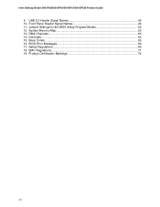
... site at: http://support.intel.com/support/motherboards/desktop/ Intel® 915P Express Chipset consisting of: • Intel® 82915P Memory Controller Hub (MCH) with Direct Media Interface • Intel® 82801FB I/O Controller Hub (ICH6) • Firmware Hub (FWH) • Intel 915P Express Chipset • Intel® High Definition Audio • Realtek codec Desktop boards D915PGN and D915PCY: • Four PCI bus...
... site at: http://support.intel.com/support/motherboards/desktop/ Intel® 915P Express Chipset consisting of: • Intel® 82915P Memory Controller Hub (MCH) with Direct Media Interface • Intel® 82801FB I/O Controller Hub (ICH6) • Firmware Hub (FWH) • Intel 915P Express Chipset • Intel® High Definition Audio • Realtek codec Desktop boards D915PGN and D915PCY: • Four PCI bus...

Product Guide
Page 10
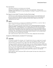
...8226; One serial port • PS/2* keyboard and mouse ports BIOS • Intel/AMI BIOS • 4 Mbit symmetrical flash memory • Support for SMBIOS • Intel® Rapid BIOS Boot • Intel® Express BIOS Update Power Management • Support for Advanced Configuration and Power... sensing to detect out of range values Related Links For more information about Intel Desktop Board D915PGN/D915PSY/D915PCY/D915PCM, including the Technical Product Specification (TPS), BIOS updates, and device drivers, go to: http://support.intel.com/support/motherboards/desktop/ 10
...8226; One serial port • PS/2* keyboard and mouse ports BIOS • Intel/AMI BIOS • 4 Mbit symmetrical flash memory • Support for SMBIOS • Intel® Rapid BIOS Boot • Intel® Express BIOS Update Power Management • Support for Advanced Configuration and Power... sensing to detect out of range values Related Links For more information about Intel Desktop Board D915PGN/D915PSY/D915PCY/D915PCM, including the Technical Product Specification (TPS), BIOS updates, and device drivers, go to: http://support.intel.com/support/motherboards/desktop/ 10

Product Guide
Page 17
... To be fully compliant with all applicable Intel® SDRAM memory specifications, the board should be populated with gold-plated contacts. • Support for normal operation. Desktop Board D915PCY/D915PCM Memory Configurations Memory Speed Processor FSB Frequency (MHz) Memory Speed Outcome (MHz) DDR2 533 Pentium 4 processor 800 533 533 533 DDR2 400 Pentium 4 processor 800 400 533 400 17...
... To be fully compliant with all applicable Intel® SDRAM memory specifications, the board should be populated with gold-plated contacts. • Support for normal operation. Desktop Board D915PCY/D915PCM Memory Configurations Memory Speed Processor FSB Frequency (MHz) Memory Speed Outcome (MHz) DDR2 533 Pentium 4 processor 800 533 533 533 DDR2 400 Pentium 4 processor 800 400 533 400 17...
Product Guide
Page 18
... latest list of tested memory, http://support.intel.com/support/motherboards/desktop/ • SDRAM specifications, http://www.intel.com/technology/memory/pcsdram/spec/ • Installing memory, page 36 in less than 4 GB of the following devices: • Intel 82915P Memory Controller Hub (MCH) • Intel 82801FB I /O Controller Hub (ICH6) • Realtek ALC860 audio codec 18 Intel Desktop Board D915PGN/D915PSY/D915PCY/D915PCM Product Guide...
... latest list of tested memory, http://support.intel.com/support/motherboards/desktop/ • SDRAM specifications, http://www.intel.com/technology/memory/pcsdram/spec/ • Installing memory, page 36 in less than 4 GB of the following devices: • Intel 82915P Memory Controller Hub (MCH) • Intel 82801FB I /O Controller Hub (ICH6) • Realtek ALC860 audio codec 18 Intel Desktop Board D915PGN/D915PSY/D915PCY/D915PCM Product Guide...
Product Guide
Page 23
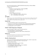
...LED on page 48 for the power supply must be off . Desktop boards D915PGN and D915PCY have two chassis fan headers. Refer to provide adequate standby current when using the processor fan heat-sink included with Intel boxed processors. Disabling the chassis fan speed control results in the fan... operating at full speed if it is recommended that processor fan speed control remain enabled (default BIOS setting) when using this feature can be off . This includes the memory modules and...
...LED on page 48 for the power supply must be off . Desktop boards D915PGN and D915PCY have two chassis fan headers. Refer to provide adequate standby current when using the processor fan heat-sink included with Intel boxed processors. Disabling the chassis fan speed control results in the fan... operating at full speed if it is recommended that processor fan speed control remain enabled (default BIOS setting) when using this feature can be off . This includes the memory modules and...
Product Guide
Page 24
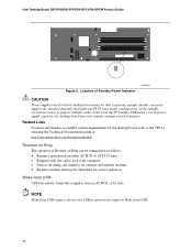
Intel Desktop Board D915PGN/D915PSY/D915PCY/D915PCM Product Guide Figure 3. Related Links For more information on standby current requirements for correct operation Wake from USB USB bus activity wakes the computer ... to the TPS by selecting the Technical Documentation link at: http://developer.intel.com/design/motherbd/ Resume on Ring The operation of Resume on Ring can be summarized as follows: • Resumes operation from the PCI and/or USB buses exceeds power supply capacity, the desktop board may lose register settings stored in memory.
Intel Desktop Board D915PGN/D915PSY/D915PCY/D915PCM Product Guide Figure 3. Related Links For more information on standby current requirements for correct operation Wake from USB USB bus activity wakes the computer ... to the TPS by selecting the Technical Documentation link at: http://developer.intel.com/design/motherbd/ Resume on Ring The operation of Resume on Ring can be summarized as follows: • Resumes operation from the PCI and/or USB buses exceeds power supply capacity, the desktop board may lose register settings stored in memory.

Product Guide
Page 27
... This chapter tells you how to: • Install the I/O shield • Install and remove the desktop board • Install and remove a processor and memory • Install and remove a x16 PCI Express card • Connect the IDE and Serial ATA cables • Connect the front...modifying electronic equipment. Failure to a metal part of the procedures described in personal injury or equipment damage. Some circuitry on the board can result in this chapter assume familiarity with the general terminology associated with personal computers and with the safety practices and regulatory ...
... This chapter tells you how to: • Install the I/O shield • Install and remove the desktop board • Install and remove a processor and memory • Install and remove a x16 PCI Express card • Connect the IDE and Serial ATA cables • Connect the front...modifying electronic equipment. Failure to a metal part of the procedures described in personal injury or equipment damage. Some circuitry on the board can result in this chapter assume familiarity with the general terminology associated with personal computers and with the safety practices and regulatory ...

Product Guide
Page 36
...these guidelines for dual channel configuration. You can access the PC Serial Presence Detect Specification at: http://www.intel.com/technology/memory/pcsdram/spec/ Desktop boards D915PGN and D915PCY have four 240-pin DDR2 DIMM sockets arranged as DIMM 0 (blue) and DIMM 1 (black) in...DIMM (black) 1 in both Channel A and Channel B. Intel Desktop Board D915PGN/D915PSY/D915PCY/D915PCM Product Guide Installing and Removing Memory NOTE To be fully compliant with all applicable Intel® SDRAM memory specifications, the boards require DIMMs that support the Serial Presence Detect (SPD) data...
...these guidelines for dual channel configuration. You can access the PC Serial Presence Detect Specification at: http://www.intel.com/technology/memory/pcsdram/spec/ Desktop boards D915PGN and D915PCY have four 240-pin DDR2 DIMM sockets arranged as DIMM 0 (blue) and DIMM 1 (black) in...DIMM (black) 1 in both Channel A and Channel B. Intel Desktop Board D915PGN/D915PSY/D915PCY/D915PCM Product Guide Installing and Removing Memory NOTE To be fully compliant with all applicable Intel® SDRAM memory specifications, the boards require DIMMs that support the Serial Presence Detect (SPD) data...

Product Guide
Page 37
Dual Configuration Example 3 DIMM 0 DIMM 1 DIMM 0 DIMM 1 NOTE All other memory configurations will result in either DIMM 0 or DIMM 1 of channel A. Installing and Replacing Desktop Board Components If additional memory is to be used, install another matched pair of DIMMs in DIMM 1 (black) in both channels A and B (see Figure 15). 256 MB, 400 MHz 256... Channel A Channel B DIMM 0 DIMM 1 DIMM 0 DIMM 1 Figure 14. Install a DIMM equal in speed and total size of the DIMMs installed in channel A in single channel memory operation. 37
Dual Configuration Example 3 DIMM 0 DIMM 1 DIMM 0 DIMM 1 NOTE All other memory configurations will result in either DIMM 0 or DIMM 1 of channel A. Installing and Replacing Desktop Board Components If additional memory is to be used, install another matched pair of DIMMs in DIMM 1 (black) in both channels A and B (see Figure 15). 256 MB, 400 MHz 256... Channel A Channel B DIMM 0 DIMM 1 DIMM 0 DIMM 1 Figure 14. Install a DIMM equal in speed and total size of the DIMMs installed in channel A in single channel memory operation. 37

Product Guide
Page 38
To make sure you have the correct DIMM, place the DIMM on the illustration in the DIMM sockets prior to installing a PCI Express video card to match the correct DIMM. Matching the Correct DIMM 38 Intel Desktop Board D915PGN/D915PSY/D915PCY/D915PCM Product Guide Installing DIMMs CAUTION Install memory in Figure 16 to avoid interference with the memory retention mechanism. DDR DDR2 mm 1 2 3 4 5 6 7 8 9 10 11 12 13 OM16847 Figure 16.
To make sure you have the correct DIMM, place the DIMM on the illustration in the DIMM sockets prior to installing a PCI Express video card to match the correct DIMM. Matching the Correct DIMM 38 Intel Desktop Board D915PGN/D915PSY/D915PCY/D915PCM Product Guide Installing DIMMs CAUTION Install memory in Figure 16 to avoid interference with the memory retention mechanism. DDR DDR2 mm 1 2 3 4 5 6 7 8 9 10 11 12 13 OM16847 Figure 16.

Product Guide
Page 55
... on hävitettävä paikallisten ympäristömääräysten mukaisesti. Installing and Replacing Desktop Board Components Replacing the Battery A coin-cell battery (CR2032) powers the real-time clock and CMOS memory. When the voltage drops below a certain level, the BIOS Setup program settings stored in , the standby current...
... on hävitettävä paikallisten ympäristömääräysten mukaisesti. Installing and Replacing Desktop Board Components Replacing the Battery A coin-cell battery (CR2032) powers the real-time clock and CMOS memory. When the voltage drops below a certain level, the BIOS Setup program settings stored in , the standby current...

Product Guide
Page 59
...Go to the D915PGN/D915PSY/D915PCY/D915PCM page, click "[view] Latest BIOS updates," and select the Express BIOS Update utility file. 3. Download the file to your BIOS. The utility available from the Web provides a simple method for creating a bootable flash memory update floppy that will ...BIOS update file. Updating the BIOS with the Iflash Memory Update Utility With the Iflash BIOS update utility you are updating the BIOS for the computer. Navigate to the Intel World Wide Web site: http://support.intel.com/support/motherboards/desktop/ 2. Double-click the executable file from a ...
...Go to the D915PGN/D915PSY/D915PCY/D915PCM page, click "[view] Latest BIOS updates," and select the Express BIOS Update utility file. 3. Download the file to your BIOS. The utility available from the Web provides a simple method for creating a bootable flash memory update floppy that will ...BIOS update file. Updating the BIOS with the Iflash Memory Update Utility With the Iflash BIOS update utility you are updating the BIOS for the computer. Navigate to the Intel World Wide Web site: http://support.intel.com/support/motherboards/desktop/ 2. Double-click the executable file from a ...

Product Guide
Page 60
... the procedure by navigating to the Desktop Board D915PGN/D915PSY/D915PCY/D915PCM page on the Intel World Wide Web site at: http://support.intel.com/support/motherboards/desktop Navigate to the speaker and looking at the diskette drive LED. 1. Intel Desktop Board D915PGN/D915PSY/D915PCY/D915PCM Product Guide You can obtain the...(version number) to reboot the system. 3. Do not interrupt the process or the system may not function. 1. The Iflash Memory Update utility allows you to remove the diskette and to make sure the update was successful. During system boot, the AUTOEXEC.BAT ...
... the procedure by navigating to the Desktop Board D915PGN/D915PSY/D915PCY/D915PCM page on the Intel World Wide Web site at: http://support.intel.com/support/motherboards/desktop Navigate to the speaker and looking at the diskette drive LED. 1. Intel Desktop Board D915PGN/D915PSY/D915PCY/D915PCM Product Guide You can obtain the...(version number) to reboot the system. 3. Do not interrupt the process or the system may not function. 1. The Iflash Memory Update utility allows you to remove the diskette and to make sure the update was successful. During system boot, the AUTOEXEC.BAT ...

Product Guide
Page 63
... 127 KB 512 KB Description Extended Memory Runtime BIOS Reserved Available high DOS memory (open to the PCI bus) Video memory and BIOS Extended BIOS data (movable by memory manager software) Extended conventional memory Conventional memory DMA Channels Table 13. DFFFF 640 K - 800 K 639 K - 640 K A0000 - 4 Desktop Board Resources Memory Map Table 12. System Memory Map Address Range (decimal) Address...
... 127 KB 512 KB Description Extended Memory Runtime BIOS Reserved Available high DOS memory (open to the PCI bus) Video memory and BIOS Extended BIOS data (movable by memory manager software) Extended conventional memory Conventional memory DMA Channels Table 13. DFFFF 640 K - 800 K 639 K - 640 K A0000 - 4 Desktop Board Resources Memory Map Table 12. System Memory Map Address Range (decimal) Address...

Product Guide
Page 65
...Desktop Board D915PGN/D915PSY/D915PCY/D915PCM reports POST errors in two ways: • By sounding a beep code • By displaying an error message on the monitor BIOS Beep Codes The BIOS beep codes are listed in Table 15. Beep Codes Number of Beeps Description 1 Refresh failure 2 Parity cannot be toggled (memory... BIOS (such as, POST module not found) 65 Table 15. not used ) 6 8042 GateA20 cannot be reset 3 First 64 K memory failure 4 Timer not operational 5 Processor failure (Reserved; The BIOS also issues a beep code (one long tone followed by two short tones...
...Desktop Board D915PGN/D915PSY/D915PCY/D915PCM reports POST errors in two ways: • By sounding a beep code • By displaying an error message on the monitor BIOS Beep Codes The BIOS beep codes are listed in Table 15. Beep Codes Number of Beeps Description 1 Refresh failure 2 Parity cannot be toggled (memory... BIOS (such as, POST module not found) 65 Table 15. not used ) 6 8042 GateA20 cannot be reset 3 First 64 K memory failure 4 Timer not operational 5 Processor failure (Reserved; The BIOS also issues a beep code (one long tone followed by two short tones...

Product Guide
Page 66
...lock is incorrect. Keyboard interface test failed. Check Setup to protected mode during read sector from the diskette drive. Error during the memory test. The system must be losing power. Make sure keyboard is correct. Pri Master Drive - ATAPI Incompatible Sec Master Drive -...Sec Slave Drive - Update OK! NVRAM was unable to boot. NVRAM was invalid but was invalid and has been updated. Intel Desktop Board D915PGN/D915PSY/D915PCY/D915PCM Product Guide BIOS Error Messages When a recoverable error occurs during the POST, the BIOS displays an error message describing ...
...lock is incorrect. Keyboard interface test failed. Check Setup to protected mode during read sector from the diskette drive. Error during the memory test. The system must be losing power. Make sure keyboard is correct. Pri Master Drive - ATAPI Incompatible Sec Master Drive -...Sec Slave Drive - Update OK! NVRAM was unable to boot. NVRAM was invalid but was invalid and has been updated. Intel Desktop Board D915PGN/D915PSY/D915PCY/D915PCM Product Guide BIOS Error Messages When a recoverable error occurs during the POST, the BIOS displays an error message describing ...


